










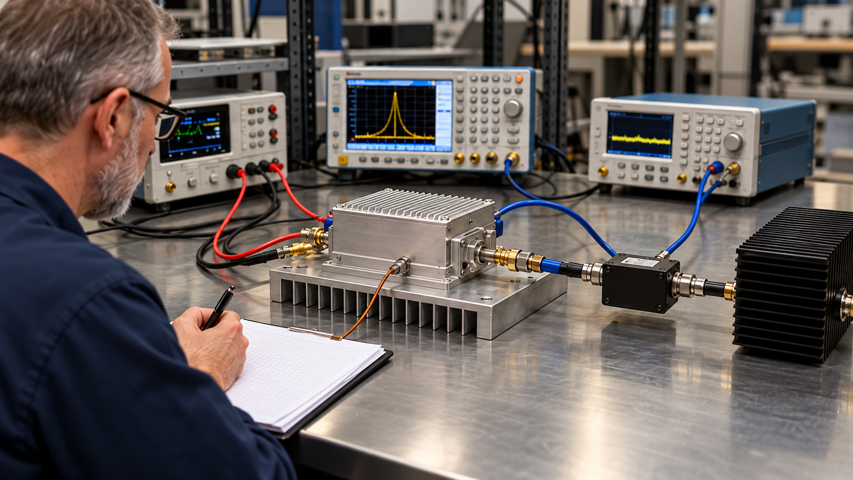
Cold vs hot RF PA efficiency can be compared at the same output power when the test conditions are controlled. Use the same amplifier, efficiency definition, RF/DC reference planes, and power-measurement method. Hold measured Pout near an agreed target, and record the actual Pin, DC voltage, and current at each thermal state.
Before interpreting an efficiency difference, confirm that the cold and hot readings describe comparable operating points. Then check whether the difference is distinguishable from measurement uncertainty. Neither calculation alone establishes the cause of the change or whether the PA meets a project requirement.
1. When Are Cold and Hot RF PA Efficiency Results Comparable?
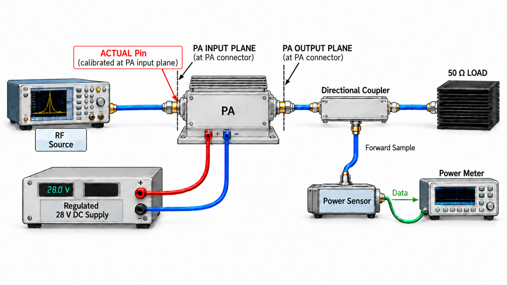
A within-unit comparison requires the same physical PA and hardware/control configuration. Two units of one model introduce unit-to-unit variation, which a cold-to-hot test of one unit is designed to avoid.
Keep frequency, waveform, duty condition, load, cooling setup, and calibrated RF paths consistent. Record ambient or cooling-inlet conditions and the temperature sensor location. Use the same DC supply boundary, including any auxiliary rails. Control the supply conditions and measure loaded Vdc at the PA terminals. Thermal state is the main comparison variable. The matched-Pout method allows drive adjustments, but actual Pin must be recorded. Any other changed condition needs a justified correction or a limit on the conclusion.
State the power definition at each PA connector reference plane. Corrected forward Pout is power traveling toward the load, which may differ from net power delivered to it. Neither value is automatically antenna-end power. Where mismatch matters, retain FWD/REV readings and use the corrections appropriate to the chosen definition.
For CW operation, distinguish fundamental-frequency power from broadband RF power. A broadband sensor may include harmonics; equal displayed totals can hide a different fundamental output, especially near compression. For modulated signals, state the measurement bandwidth and averaging method. At the PA input, identify whether Pin means incident or accepted power.
Module DC-to-RF efficiency, PAE, and transistor drain efficiency also have different power boundaries. The PAE and drain-efficiency comparison explains the distinction.
If a critical power definition, reference plane, load, DC boundary, or thermal state remains unresolved, hold the comparison until it can be verified or corrected.
2. Should RF Input Power or Output Power Stay Fixed?
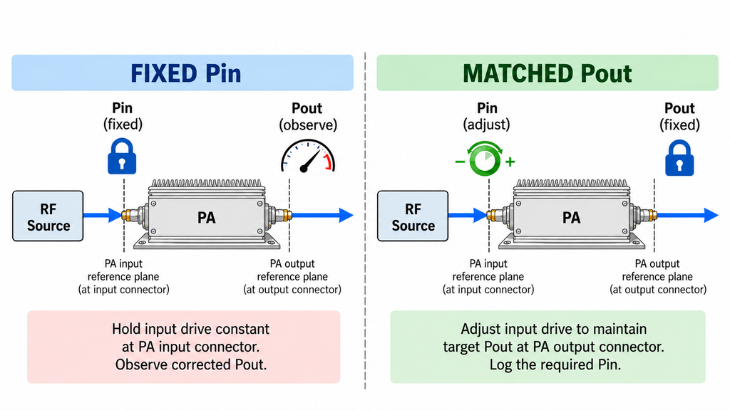
Use fixed Pin to observe performance drift under unchanged RF drive. Use matched Pout to measure the drive and DC power needed to sustain one output level. Keep the two test modes separate when comparing efficiency.
Fixed-Pin Test: Observe Thermal Performance Drift
Keep measured Pin at the PA input reference plane constant. Record Pout, terminal Vdc and Idc, and efficiency as the module warms. If Pout changes, the readings represent different output operating points. This test can reveal drive-to-output drift, but it cannot isolate the DC burden at equal Pout. Measure Pin at the PA connector rather than relying on the signal generator setting.
Matched-Pout Test: Compare RF Drive and DC Burden
Hold measured Pout at the PA output reference plane within a specified tolerance. Adjust drive when needed, and log actual Pin, Vdc, and Idc. Keep waveform, load, supply limits, and power corrections consistent. Pin and Idc are measured responses, not extra fixed conditions.
Normal gain compression does not invalidate the comparison if target Pout, waveform requirements, and operating limits are met. If the hot PA cannot sustain the target, or protection changes the agreed test mode, report the actual shortfall. Thermal-soak output-power verification addresses that separate issue.
Keep the actual cold and hot Pout values even when both fall within tolerance. The remaining difference may affect the efficiency calculation.
3. How Should Cold, Warm, and Stabilized Hot-State Data Be Captured?
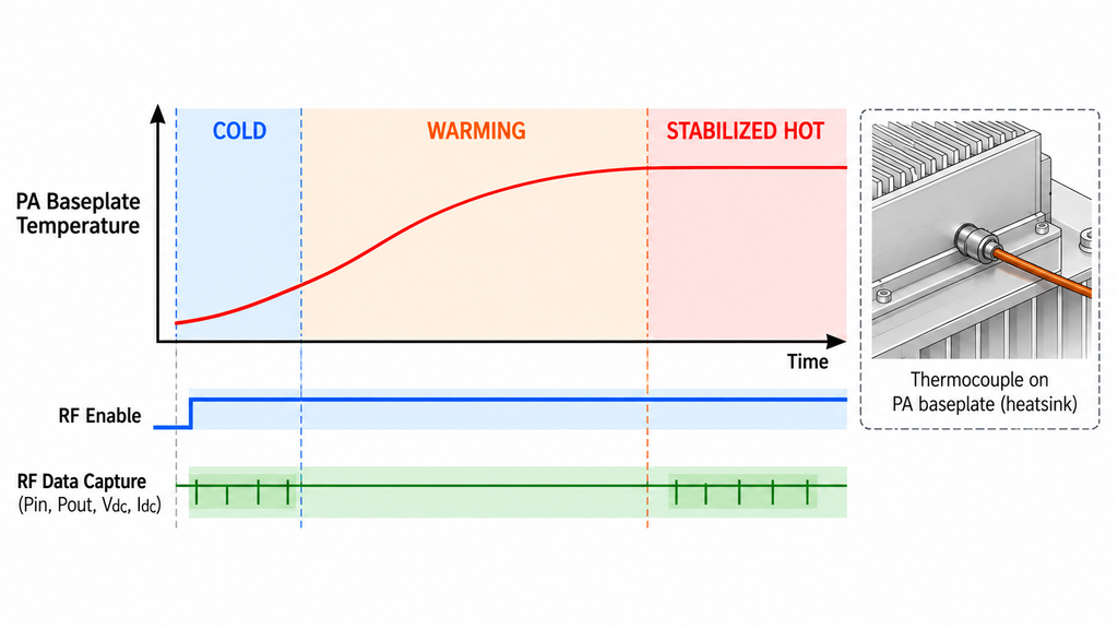
Define the temperature states before testing. For the cold point, record preconditioning, RF-enable time, temperature, and sampling window. Label intermediate points warming. A stabilized hot point must satisfy the agreed temperature and electrical stability criteria; elapsed time alone does not establish steady state. If drive is changed to restore Pout, confirm stability again before recording the hot reading. A baseplate or heatsink reading is not junction temperature.
At each state, capture corrected Pin and Pout, terminal Vdc and Idc, temperature, and load/reflected-power status over aligned time windows. Log drive, bias, or protection changes. Retain raw readings, calibration corrections, timestamps, and averaging methods. The continuous-CW efficiency test covers the broader hot-state observation procedure.
Repeated samples in one stable window show short-term variation, not cycle-to-cycle repeatability. For a claim about repeated cold-to-hot operation, cool the PA and run additional cycles. Without a qualified hot window or synchronized RF/DC readings, the record supports only a warming-stage observation.
4. How Do You Calculate Cold-to-Hot RF PA Efficiency Change?
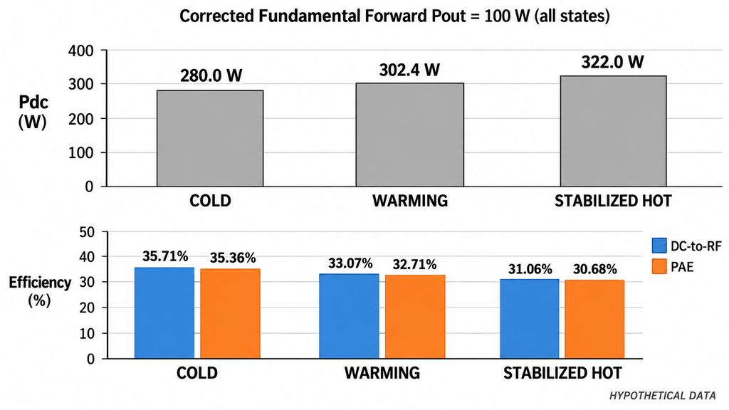
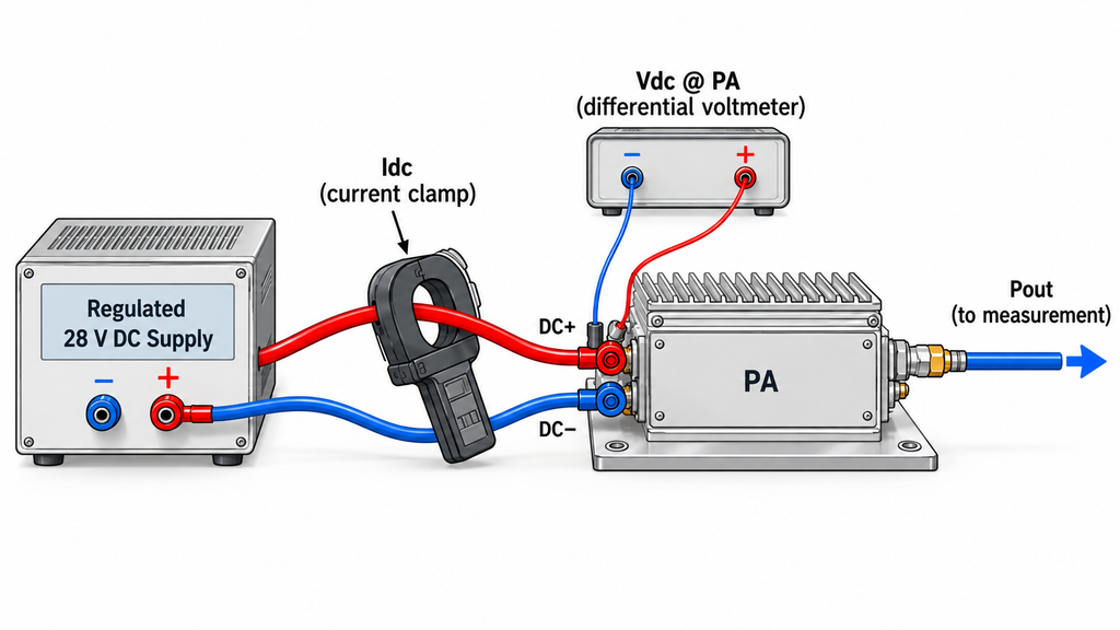
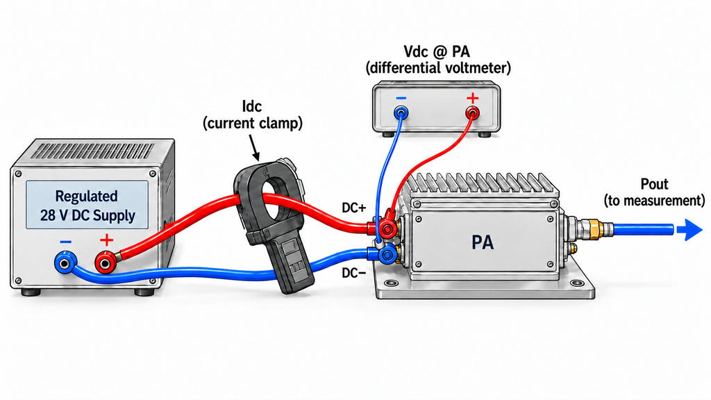
For one complete DC input with nearly constant voltage and current, Pdc = Vdc × Idc. If they vary during the measurement window, calculate Pdc = average[Vdc(t) × Idc(t)] from synchronized samples. Multiplying separately averaged voltage and current may give the wrong result. Include all relevant supply rails within the selected DC boundary, using aligned RF and DC averaging windows.
To calculate RF power amplifier efficiency at the declared module boundary, use DC-to-RF efficiency = (Pout / Pdc) × 100% and PAE = [(Pout − Pin) / Pdc] × 100%. Convert dBm to watts before using the formulas. Neither result is necessarily transistor drain efficiency.
The following numbers are hypothetical, not RF SKYPOWER measurements or product specifications. Assume a single DC input measured at 28.0 V at the PA terminals and CW operation at one frequency. Pin is calibrated incident power at the PA input reference plane. Pout is corrected fundamental-frequency forward power at the output plane, measured without harmonic contributions. Input and output reflections have been checked at the PA reference planes and are negligible under documented limits. Incident Pin and forward Pout therefore approximate accepted input and net delivered fundamental output, respectively. A nominal 50-ohm test setup alone would not establish this match. Separate time and temperature records qualify all three thermal states.
| Measured or calculated quantity | Cold | Warming | Stabilized hot |
|---|---|---|---|
| Pout (W) | 100 | 100 | 100 |
| Pin (W) | 1.0 | 1.1 | 1.2 |
| Vdc at module (V) | 28.0 | 28.0 | 28.0 |
| Idc (A) | 10.0 | 10.8 | 11.5 |
| Pdc (W) | 280.0 | 302.4 | 322.0 |
| Module DC-to-RF efficiency (%) | 35.71 | 33.07 | 31.06 |
| PAE (%) | 35.36 | 32.71 | 30.68 |
Using unrounded values, module efficiency falls by 4.66 percentage points (pp) from cold to stabilized hot, a 13.0% relative decrease. At the same 100 W output, Pdc rises by 42 W, Idc by 1.5 A, and required Pin by 0.2 W. The extra DC input cannot be labeled an equal increase in heat without a consistent energy balance.
Without an uncertainty budget, these calculated values cannot confirm a thermal effect or an acceptance result.
5. Is the Measured Efficiency Difference Larger Than Test Uncertainty?
Calculate Δη = ηhot − ηcold from unrounded efficiencies, in percentage points. Before interpreting it, examine any remaining Pout mismatch and the uncertainty of the measurements.
Both states can meet a 100 W tolerance while their actual outputs differ. Because efficiency depends on operating point, part of the apparent cold-to-hot change may come from that difference. For scale, 1 W divided by a fixed 280 W Pdc changes the calculated efficiency by about 0.36 pp. This illustrates sensitivity, not a correction: Pdc may also change with Pout.
Retesting closer to a common measured output is preferable. Alternatively, use validated efficiency-versus-Pout data for each thermal state to correct both points to one output level, including correction uncertainty. If the remaining mismatch cannot be resolved, qualify the comparison rather than assigning the full change to thermal state.
Now assess the uncertainty of the difference, including RF sensor calibration, coupler and cable corrections, mismatch, DC meter accuracy, timing, and test-chain drift. Use repeat measurements where appropriate. Errors shared between cold and hot readings may be correlated. For two efficiency estimates:
u_c²(Δη) = u_c²(ηhot) + u_c²(ηcold) − 2 × Cov(ηhot, ηcold)
Here u_c is combined standard uncertainty and Cov is covariance. Use consistent percentage-point units. The formula requires a valid measurement model and defensible estimates of the uncertainty terms, including covariance. Setting covariance to zero without evidence may misstate the result.
If the adopted method supports a symmetric expanded interval, use UΔ = k × u_c(Δη), stating the coverage factor k and intended coverage. Report the result as Δη ± UΔ in pp. An interval excluding zero supports a nonzero difference at the stated coverage. If zero lies inside it, the measurement has not established a nonzero change at that coverage; equality has not been proved either.
For the hypothetical result, Δη is about −4.66 pp. Its symmetric interval would exclude zero only if UΔ were smaller than the absolute unrounded difference. The example supplies no UΔ, so the change remains an observation. Even a measured nonzero difference does not establish temperature as its sole cause.
6. Does Higher Hot-State Current Prove Lower PA Efficiency?
An increase in RF amplifier current consumption does not, by itself, demonstrate a loss of efficiency. The relevant denominator is DC input power. If terminal Vdc falls while Idc rises, Pdc could increase, remain unchanged, or decrease. PAE also depends on actual Pin.
At matched Pout, a verified rise in Pdc means lower module DC-to-RF efficiency by definition. That arithmetic cannot isolate the cause. Check supply voltage, bias, load mismatch, and protection activity before attributing the change to heating. A current trace alone cannot establish thermal runaway, damage, or a manufacturing defect.
7. How Should a Thermal-State Efficiency Comparison Be Accepted?
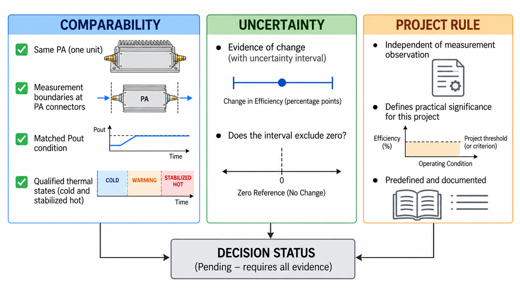
The decision has three parts: whether the operating points are comparable, whether the efficiency difference can be distinguished from measurement uncertainty, and whether the result meets the project’s acceptance rule.
| Comparison category | Conditions and evidence status | Permitted conclusion | Next engineering action |
|---|---|---|---|
| Directly comparable | Same metric and RF/DC boundaries; qualified thermal states; matched or validly corrected Pout; traceable measurements. Difference uncertainty may still be unknown. | Report the observed difference. Claim a distinguishable change only with adequate uncertainty evidence. Do not infer product pass/fail. | Assess difference uncertainty, then apply the agreed project limit and decision rule. |
| Partially comparable | A known condition or remaining Pout mismatch may be correctable, but the correction is not yet supported. | Report condition-limited results. Do not assign the apparent difference entirely to thermal state. | Obtain missing records, validate a correction, or repeat the affected measurement. |
| Not comparable yet | A critical metric, reference plane, operating mode, load, or hot-state qualification cannot be aligned. | No valid matched-output cold-to-hot efficiency difference can be claimed. | Use one measurement protocol and retest the affected states. |
An RF amplifier test report may contain directly comparable cold and hot readings but still lack the uncertainty evidence needed to confirm a change. And a confirmed change may still meet the project specification. Identify whether the requirement concerns minimum hot-state efficiency or maximum cold-to-hot loss. Apply the agreed conformity rule, whether simple acceptance, a guard band, or another defined method. Record how uncertainty and decision risk are handled. If the rule cannot support a decision with the available evidence, report the result as inconclusive. A comparison on hold is not a failed product.
Conclusion
Equal 100 W readings do not prove equal cold- and hot-state efficiency. A valid comparison requires the same PA, a defined efficiency metric, consistent RF/DC boundaries, and qualified thermal states. Correct or disclose material output mismatch, then evaluate uncertainty in the efficiency difference. Neither higher current nor a confirmed efficiency loss establishes thermal damage. Product acceptance still depends on a stated requirement and decision rule.
Classify the available records, obtain missing corrections or repeat the affected measurement, and apply the project’s efficiency limit. The method cannot supply a universal allowable thermal loss.
Engineers can review RF power amplifier module families while defining a model-specific requirement. For an RF SKYPOWER engineering review, provide frequency, waveform and duty cycle, Pout target and tolerance, and both RF reference planes. Include the Pin control mode, efficiency definition, DC boundary and supply limits, cooling and load conditions, and thermal stability window. Supply the acceptance criterion, raw readings, corrections, and uncertainty requirements. These inputs define the evidence needed for an engineering review; model-specific performance and acceptance still require supporting test results.