










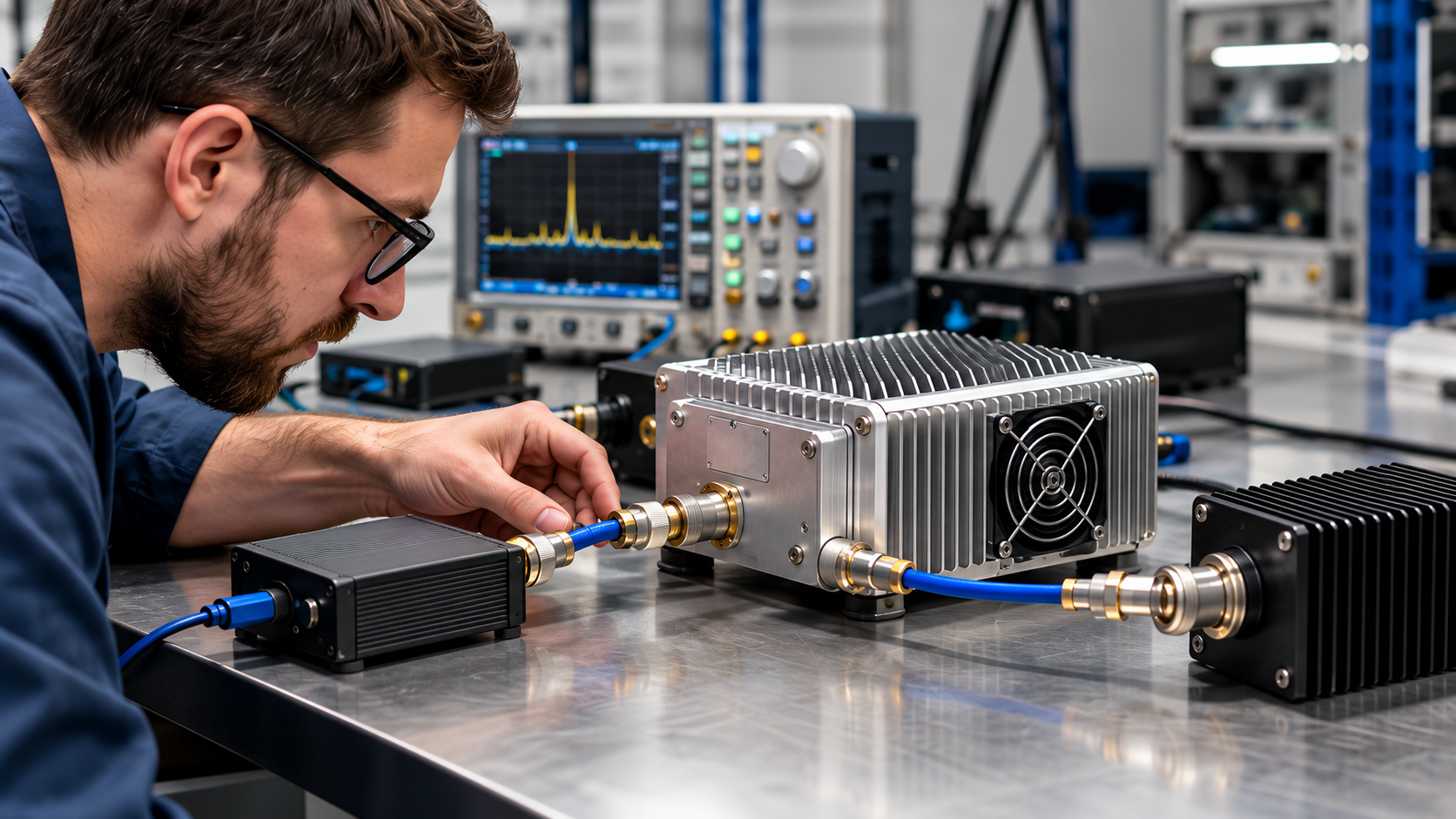
When an SDR-to-PA chain produces low RF output, locate the first power shortfall before treating the amplifier as faulty. RF PA low output troubleshooting starts by verifying the drive reaching the PA input under the relevant frequency, waveform, load, and operating conditions.
The cause may be insufficient SDR output, interstage loss, control or protection behavior, or a downstream RF problem. Before requesting repair or RMA, engineers need measurements that distinguish these possibilities without changing several test conditions at once.
1. Where Is the Low RF Output Actually Observed?
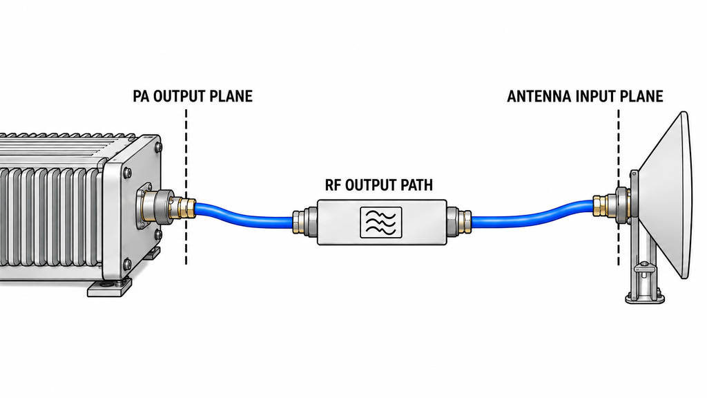
Start by locating the low reading: the PA output connector, a downstream measurement point, or the antenna feed.
A reading taken after a cable, filter, switch, or other RF component cannot establish PA performance on its own. Record the measurement reference plane, instrument, correction factors, operating frequency, waveform, and expected power limit at that location. Keep raw readings separate from corrected results.
With a mismatched output load, distinguish corrected forward power from net power crossing the PA-output reference plane. Calculate net power from compatible forward and reflected measurements in linear power units. Neither reading alone establishes power delivered at the antenna end.
The load condition also matters. If PA-port output meets its applicable limit under the installed-path load while downstream power is unexpectedly low, investigate the intervening output path. A normal PA output reading taken with a separate matched dummy load cannot establish how the amplifier behaves with the installed antenna path connected.
An inactive Enable state or a latched alarm can suppress RF even with valid input drive. Record the control-interface command and alarm sequence before interpreting low output as a gain problem.
If the measurement reference plane or operating state remains unknown, hold the component-failure judgment.
2. Is the SDR Delivering the Expected RF Power?
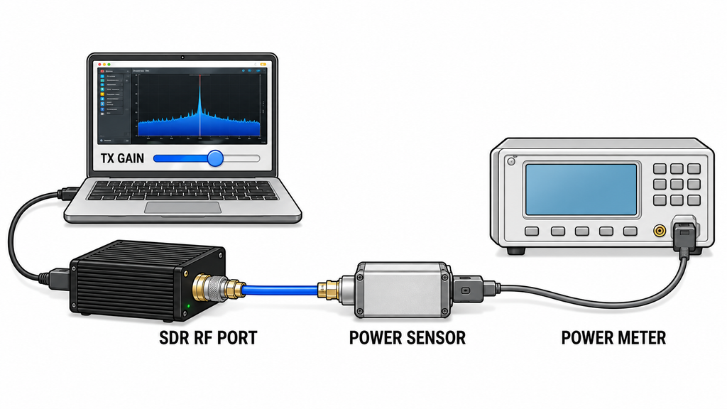
An SDR transmit-gain setting cannot substitute for measured RF output power. Actual output depends on frequency, waveform, digital amplitude, RF gain, and hardware operating conditions.
Measure or calibrate power at the SDR RF connector using the relevant waveform and power definition. CW power, full-cycle average power, and on-pulse power are different measurement quantities. Record the loading and instrument conditions used to obtain the result.
Derive the required SDR-port output from the PA’s documented input-drive requirement and the verified gain or loss of the intervening source path. A direct comparison between SDR-port power and the PA input requirement is valid only when the complete intervening path has been accounted for.
Use the SDR-port measurement to select the next test:
- SDR-port power is below the derived requirement: Check SDR configuration, source output capability, and source-side hardware before investigating PA performance.
- SDR-port power meets the requirement: Continue to the PA input reference plane. Adequate SDR-port output does not guarantee adequate drive at the amplifier.
If the required source level or intervening path characteristics are unknown, the SDR-versus-PA judgment remains unresolved.
3. Is RF Drive Being Lost Between the SDR and PA Input?
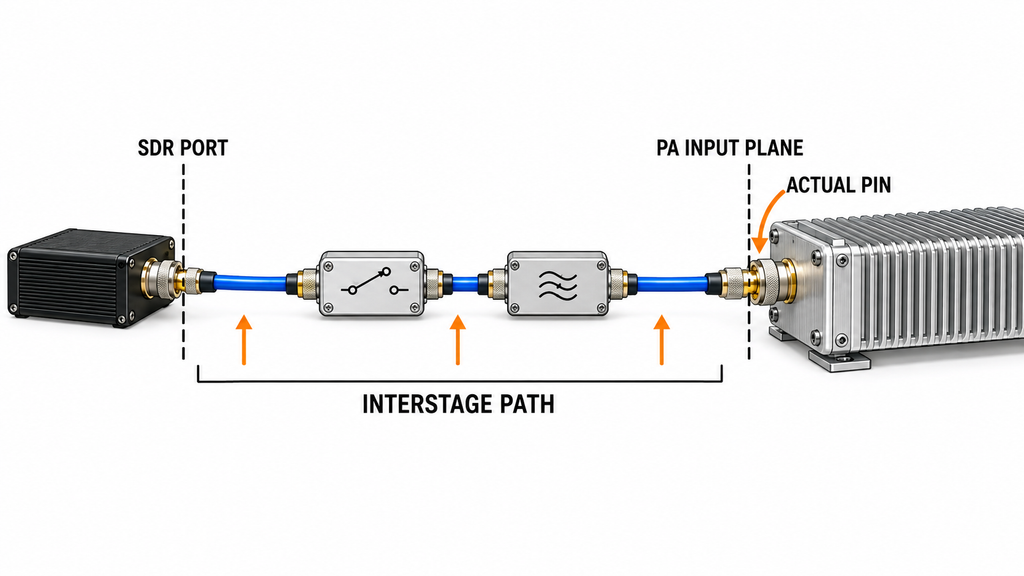
Cable attenuation, connector condition, switch selection, filtering, fixed attenuation, and the operating state of an intermediate driver stage can all change the drive reaching the PA.
Compare measured SDR-port output with Actual Pin at the PA input reference plane. Define that plane at the PA RF input connector. Record the measured power quantity, calibration method, and corrections.
To diagnose interstage loss, compare compatible SDR-port and calibrated PA-input measurements under documented path conditions. Different power definitions or unverified corrections can produce a misleading loss estimate.
A source-path calibration into a specified matched termination establishes power under that termination. By itself, it does not establish incident or accepted power at the connected PA input. Before comparing Actual Pin with the required input level, verify that the power definition and measurement conditions match the applicable product specification.
If SDR-port power is adequate but verified PA input drive is low, investigate the interstage path first. Compare its measured gain or loss with the applicable path allowance. Assign a component fault only when the deviation is large enough to distinguish from measurement uncertainty.
Do not compensate for unknown loss by increasing SDR output blindly. The adjustment could restore output at one frequency while exceeding the PA’s permitted input range elsewhere.
4. Does the PA Recover Under Controlled Reference Drive?
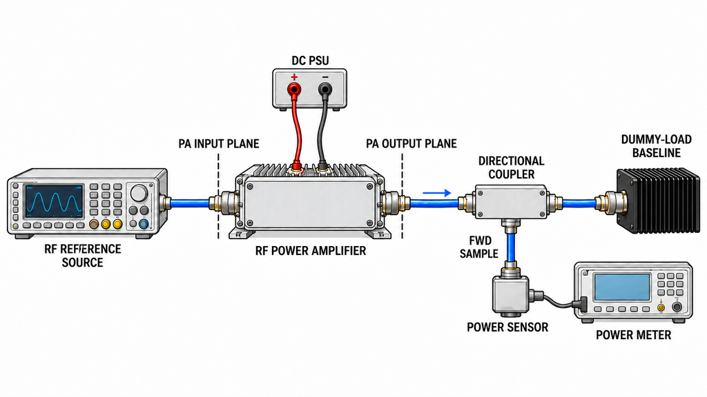
A controlled reference-source test checks whether the PA can meet its output requirement with valid RF drive at its input. Use the applicable model-specific input limits and a suitably rated, safely terminated RF output setup.
Required-Pin verification: Apply the model’s documented, permitted RF amplifier input drive level at the PA input reference plane, using the specified power definition. Keep frequency, waveform, duty cycle, output load, PA-terminal DC voltage, Enable state, and relevant thermal conditions consistent with the reported fault. Compare corrected PA-port output with the applicable requirement.
If the original Actual Pin was demonstrably low and output recovers at the required drive, underdrive is supported for that operating point. This test cannot distinguish insufficient SDR-port output from interstage loss. It also cannot rule out an intermittent PA-side problem under other conditions.
If corrected PA-port output remains low despite valid drive, DC supply, control state, and load conditions, investigate the PA side. The result still requires confirmation before declaring an output-stage defect or authorizing RMA.
Same-Pin source comparison, when needed: If waveform-related differences remain uncertain, compare the original SDR and reference source at the same verified input-power level and otherwise comparable conditions. Different PA output results call for further investigation of source or waveform characteristics; they do not establish hardware failure by themselves.
A CW-only reference test cannot confirm performance under the original modulated waveform.
To localize an upstream deficit, check the usable drive margin through the installed source path against the measured interstage gain or loss.
Stop the comparison if the input limit, power definition, waveform conditions, reference plane, or applied corrections cannot be established reliably.
5. Which Results Point to an SDR, RF Path, or PA-Side Problem?
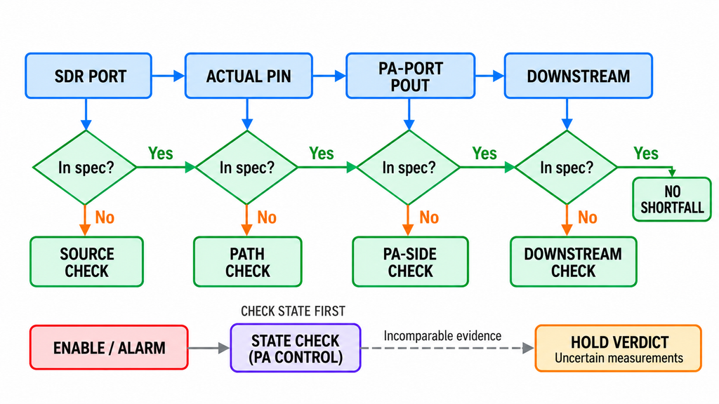
Use the first verified divergence to select the next isolation test. A dummy-load baseline and an installed antenna-chain check involve different loads and cannot establish the same fault location by direct comparison.
Treat each first suspect as provisional. A power shortfall within measurement uncertainty cannot support a definitive component-failure judgment.
| Observed Result | Key Measurement Evidence | First Suspect | Next Isolation Test | Permitted Conclusion / Stop Condition |
|---|---|---|---|---|
| SDR-port output is below the derived requirement | Calibrated SDR-port power and required source level for the tested operating point | SDR configuration or source output chain | Recheck waveform, gain configuration, source attenuation, and measured port output | Source-side underdrive is supported if the deficit is measurement-resolvable; PA failure is not established |
| SDR-port power is adequate, but Actual Pin is low | Compatible source-port and PA-input power definitions with documented path corrections | Interstage RF path | Verify cable, switch, filter, attenuator, and driver-stage gain or loss | Assign abnormal interstage loss only when its measured deviation exceeds the applicable allowance and is distinguishable from measurement uncertainty |
| Original Actual Pin is low, and output recovers at required Pin | Original low-drive record and controlled retest with valid, comparable PA input drive | Insufficient upstream drive | Separate SDR-port capability from intervening path loss | Underdrive is supported; SDR-versus-path ownership remains open |
| Required Pin is valid, but corrected PA-port Pout remains low | Comparable frequency, waveform, load, DC, thermal, and input conditions; valid Enable state and no unresolved protection event | PA-side performance or unverified test condition | Recheck corrections, measurement uncertainty, operating state, and the unit’s applicable output requirement | Escalate PA-side diagnosis only if the shortfall is substantiated; hardware failure and RMA authorization remain unconfirmed |
| RF output is inhibited or an alarm is active | Enable command, reported state, alarm history, and loaded PA-terminal DC readings | Control, protection, or supply condition | Verify the applicable control and protection sequence | Resolve the operating-state discrepancy before judging RF gain |
| PA-port output meets its applicable limit under the installed load, but downstream power is unexpectedly low | Comparable power quantities, reference planes, measurement windows, corrections, relevant FWD/REV readings, permitted path loss, and measurement uncertainty | Downstream RF path or measurement error | Verify path insertion loss and measurement corrections without materially changing the load | Prioritize the downstream path only when excess loss is reproducible and distinguishable from measurement uncertainty under the applicable project decision rule; otherwise hold fault assignment |
| PA passes with a matched dummy load, but installed-path output is low | Results obtained under different output-load conditions | Load-dependent behavior or installed RF path | Measure PA-port behavior under the installed load and review FWD, REV, and control state | Do not assign the fault from the two non-equivalent tests alone |
| Measurements use inconsistent waveforms, power definitions, reference planes, or corrections | Missing or conflicting test conditions and instrument records | Test configuration or evidence quality | Reconcile the conditions or repeat the affected measurement | Hold the component verdict and RMA decision until evidence is comparable |
6. What Evidence Is Needed Before Requesting PA Repair or RMA?
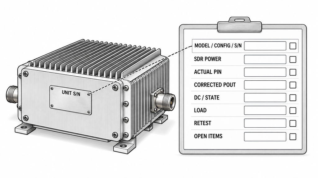
A pre-RMA record should allow the manufacturer and system integrator to reproduce the reported operating condition and identify the part of the RF chain still under investigation.
Collect the following evidence for the affected unit:
- Unit identity: PA model, configuration, serial number, hardware revision where relevant, and any unit-specific RF amplifier test report available for comparison.
- Applicable requirement: Datasheet or agreed project specification, document revision, required Pin and Pout, frequency range, waveform, and acceptance conditions.
- Reported symptom: Frequency, waveform, channel or bandwidth, duty cycle, power metric, failure timing, duration, and whether the shortfall is continuous or intermittent.
- SDR-port output: Measured RF power at the source connector, source configuration, measurement conditions, instrument, calibration status, and applicable source-output requirement.
- PA input drive: Actual Pin at the defined PA input reference plane, the measured power definition, source-path configuration, correction factors, calibration method, and relevant measurement uncertainty or mismatch limitation.
- PA output: Raw and corrected Pout, measurement reference plane, power definition, instrument calibration status, coupler and path corrections, estimated measurement uncertainty, and the applicable limit.
- DC and operating state: Loaded voltage at the PA terminals, current, Enable status, alarm or protection history, reset state where relevant, and recorded thermal condition.
- Output load: Dummy-load or installed-path configuration, relevant FWD/REV measurements, VSWR where available, and any observed load-dependent behavior.
- Controlled retest: Required-Pin result, reference-source conditions, optional same-Pin comparison, and all differences from the original failing setup.
- Engineering disposition: First verified point of divergence, remaining uncertainty, proposed next isolation test, and the person responsible for the decision.
When factory and field measurements disagree, a same-condition comparison of RF PA power-test results depends on recorded reference planes, corrections, and operating conditions for both tests. A report from another unit cannot establish the condition of the unit under investigation.
If the requested frequency, drive level, or output condition falls outside the ordered PA’s documented operating limits, investigate the configuration or specification mismatch before initiating repair. The RF power amplifier product range can help identify alternative module families, but the exact replacement configuration still requires confirmation.
Conclusion
PA-side repair investigation is justified when the shortfall has been localized and corrected PA-port output remains below its applicable limit under verified, permitted input drive and comparable operating conditions. Recovery at the required Pin supports upstream underdrive if the original input was insufficient, but it leaves SDR-versus-path fault ownership unresolved.
This isolation sequence identifies the next engineering test. Model-specific input limits, output acceptance thresholds, protection requirements, and RMA eligibility still depend on the applicable product and project documentation. An SDR software gain setting alone never proves that adequate drive reached the PA input.
Before requesting a return, preserve the original failure record, complete the evidence checklist, and document any remaining reproducible PA-side shortfall. If the case remains unresolved, send the record to the RF SKYPOWER engineering team for review of the next action. Engineering review does not itself confirm a hardware defect or authorize RMA.