










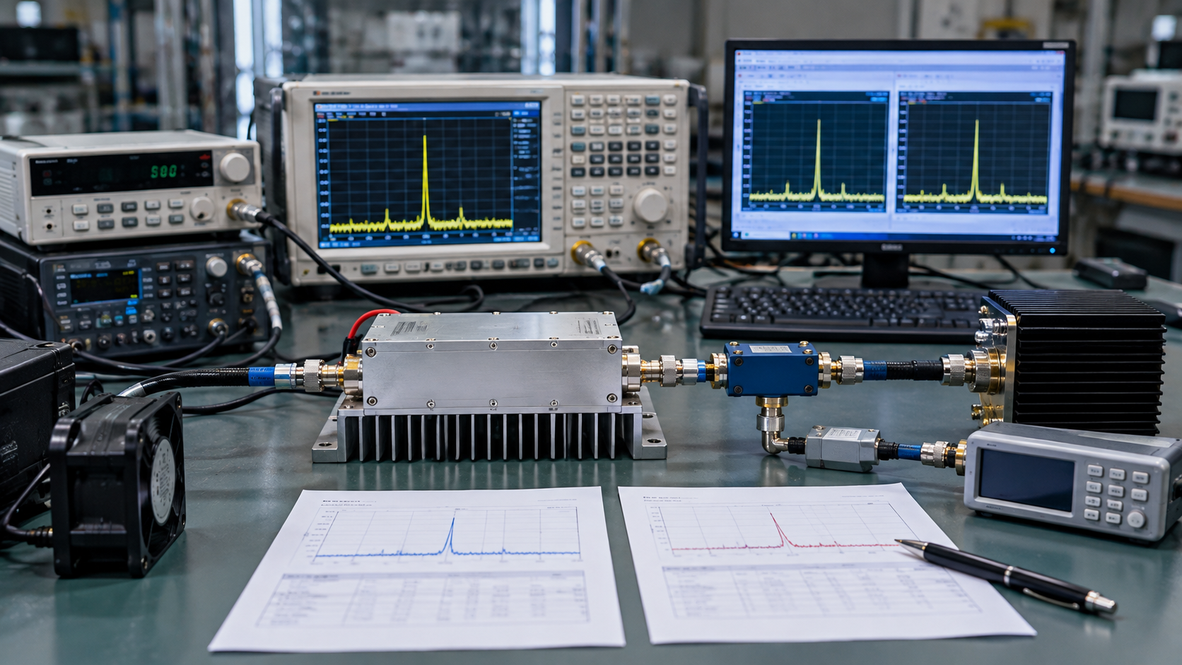
Factory and customer laboratories can report different RF power amplifier (RF PA) output power values even when the amplifier has not changed. These RF PA retest differences can arise from different reference planes, path corrections, input drive, loads, instrument settings, or thermal conditions. A persistent difference may also reflect a real change in PA behavior; neither laboratory’s reading should be presumed correct merely because it came from a factory or an independent lab.
Before comparing the readings, establish that they represent the same RF quantity at the same reference plane under comparable operating conditions. Until that is established, subtracting the reported wattages cannot establish a power shortfall or an acceptance failure.
Begin with the measurement records.
1. Are the Factory and Customer Power Results Measuring the Same Quantity?
First verify that the factory’s RF amplifier test report and the customer’s retest records refer to the same physical PA. Record the model, serial number (S/N), hardware revision, and relevant firmware, bias, or control configuration. Two samples of the same model can support a production-consistency study, but comparing them is not a retest of one delivered unit. If the module was serviced or reconfigured between measurements, that change belongs in the investigation.
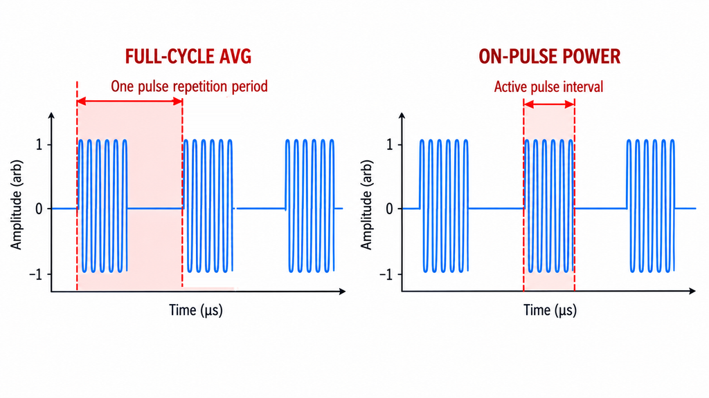
Then identify the signal and power quantity. Continuous-wave (CW) operation, pulsed operation, and a modulated waveform describe different signal conditions. Average power, pulse power, peak power, and peak-envelope power where applicable describe different reported metrics. For a pulsed signal, an average over the full pulse cycle can differ from the power during the active pulse without any change in the pulse’s on-state level. The measurement instrument must be configured for the quantity being compared.
Also distinguish forward power at a directional coupler, net power delivered to a mismatched load, and power at a downstream cable end. Even with identical units of dBm or watts, they need not describe the same measurand—the quantity intended to be measured.
If the S/N, power metric, test frequency, waveform, or underlying operating point cannot be established, the readings are not comparable yet. Recover the missing test definitions before diagnosing an apparent PA failure. The general definition of suitable RF test conditions belongs to RF power amplifier testing methods and conditions; the task here is to reconcile two existing reports.
2. How Do Reference Planes and RF Path Corrections Change the Reported Pout?
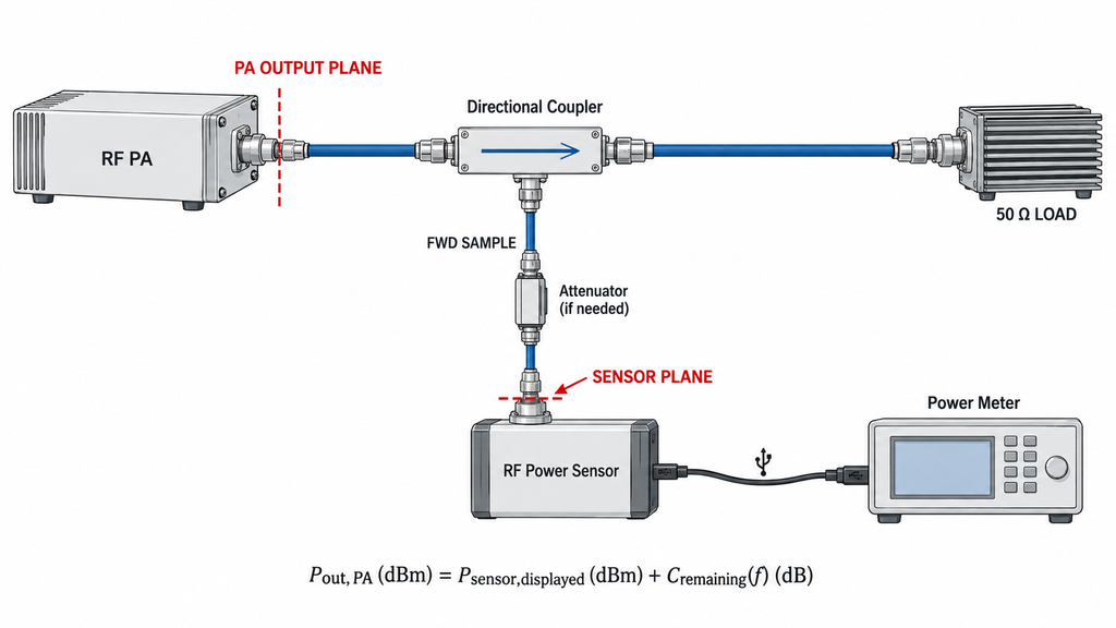
The reference plane determines where reported output power, Pout, applies. A factory may report corrected power at the PA output connector, while a customer records power at a sensor behind a coupler, attenuator, and cable. A comparison requires translating both readings to an agreed plane.
Trace each measurement path from the PA connector to its sensor. Identify the coupler port used, the attenuator and cable assembly, and any correction already enabled in the meter or test software. A final Pout value without its correction history leaves the disputed result difficult to reconstruct.
Raw Readings Versus Corrected PA-Port Power
For a characterized measurement path where a scalar power correction is appropriate, a convenient expression in logarithmic units is:
Pout,PA (dBm) = Psensor,displayed (dBm) + Cremaining(f) (dB)
Here Cremaining(f) is only the net path or fixture correction still needed to translate the displayed sensor result to the agreed PA-output reference plane at frequency f. Its sign depends on the measurement path and the correction convention. If the meter already applies a cable, attenuation, or coupling correction, that contribution must not be added a second time.
Sensor calibration and RF-path translation serve different purposes. A valid calibration factor helps the sensor produce a meaningful reading at its own measurement interface, with associated uncertainty. The path correction relates that calibrated reading to another physical reference plane. Do not treat a sensor’s calibration status as an extra number of decibels to append to the path-loss total.
The simple expression above does not automatically resolve source–load mismatch, directivity, or other complex transfer effects. When these are significant, use an appropriate characterized method and uncertainty model rather than claiming that an arbitrary scalar offset reconstructs the true PA-port power.
Coupler Sample-Path Correction Versus Mainline Loss
For a PA feeding a directional coupler, cable, and dummy load, the sampled forward-power path and the high-power mainline serve different purposes. Coupling factor, sample-path attenuation, and the applicable measurement configuration affect how the sensor’s sampled reading is related to forward power at the chosen coupler reference plane. Coupler directivity and mismatch may also contribute error, particularly when significant reflected power is present.
The high-power cable between the coupler and load has a separate insertion-loss and mismatch boundary. Its loss affects power delivered downstream; it is not automatically an additional correction to the coupled forward-power reading. Nor does the coupler’s location automatically make its reported value equal to PA-connector Pout.
Both laboratories should retain the raw readings and correction records alongside their final Pout figures. Use the common record below to identify where the reports agree, where a valid correction can reconcile them, and where a new measurement is needed.
Factory–Customer RF PA Retest Comparability Record
| Check item | Factory record | Customer record | Comparability status | Missing evidence / required action |
|---|---|---|---|---|
| PA S/N and configuration | — | — | — | Verify the same S/N and configuration; otherwise this is not a same-unit retest |
| Frequency and waveform | — | — | — | Align conditions or document a technically justified equivalence |
| Power metric and meter mode | — | — | — | Match the metric and acquisition mode; use a conversion only if validated for the signal |
| Actual Pin at the PA input | — | — | — | Verify input-plane drive and whether it was fixed or adjusted |
| Pout reference plane | — | — | — | Identify both planes and apply a valid translation if needed |
| Raw sensor readings | — | — | — | Retrieve original readings, units, and active meter corrections |
| Corrected PA-port Pout | — | — | — | Reconstruct both results at the agreed plane without discarding raw data |
| Coupler, attenuator, cable corrections | — | — | — | Verify frequency, correction sign, and whether each term was already applied |
| Load, RF cables, and mismatch | — | — | — | Record assemblies, relevant reflection data, and load suitability |
| Vdc, Idc, and operating state | — | — | — | Measure or recover terminal values under RF drive and the control state |
| Cooling, temperature, and duration | — | — | — | Identify cold, fixed-dwell, or stabilized-hot conditions and cooling |
| Meter/sensor IDs and calibration | — | — | — | Verify IDs, applicable calibration, measurement mode, range, and settings |
| Uncertainty and comparison rule | — | — | — | Evaluate uncertainty of the difference and the applicable comparison criterion |
Complete the blank status cells only after reviewing the two records. Use Comparable when conditions match or a justified correction establishes equivalence; Partially comparable when some comparison evidence is available but a material condition or uncertainty remains unresolved; and Not comparable yet when missing or incompatible information prevents that comparison. Different average, pulse, or peak metrics cannot be compared directly, but a validated signal-specific relationship may support a defined conversion. An unresolved essential condition prevents a defensible overall power-agreement conclusion. Blank cells never imply that the conditions match.
For a detailed method beyond this comparison record, consult the test cable loss compensation verification method.
3. Could Input Drive, Signal Type, or Measurement Settings Explain the Difference?
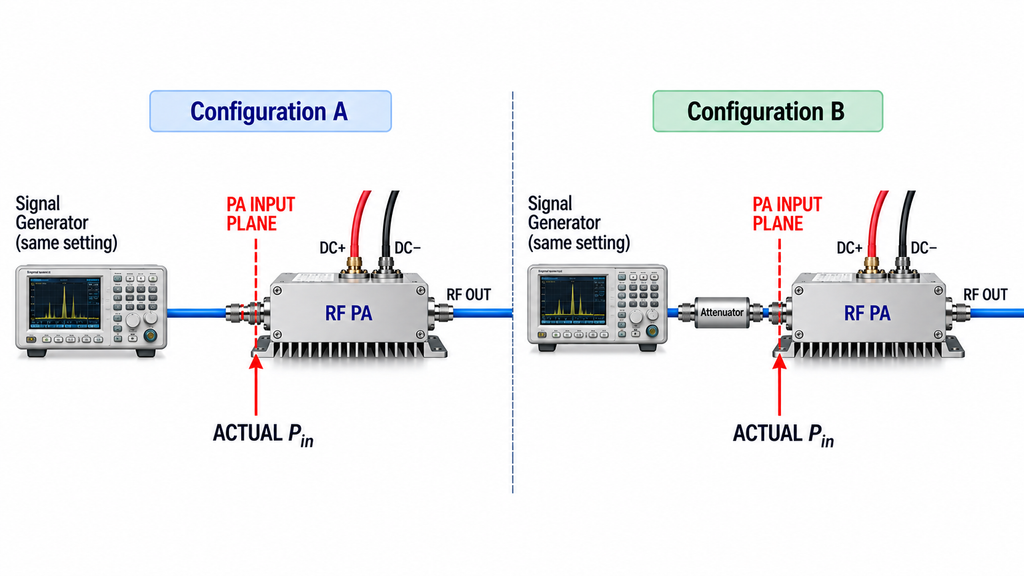
Two laboratories may use the same signal-generator power setting but deliver different actual Pin to the amplifier. Input cables, adapters, attenuation, and other fixtures can change the power at the PA input reference plane. The generator display alone cannot establish that reference-plane value.
Check whether the test held Pin constant or adjusted it. Under fixed Pin, the laboratories observe Pout at an agreed input drive. Under adjusted Pin, an operator or controller changes drive to meet a target output. A Pout reading obtained after raising Pin cannot be presented as equivalent to a fixed-drive result without acknowledging the changed operating point and any specified drive limit.
For pulsed or modulated tests, align waveform parameters, duty cycle, and the instrument’s acquisition method. A meter integrating across a complete pulse cycle may report a different quantity from an instrument gating its measurement to the active portion. Averaging, triggering, and sensor suitability must match the agreed metric. Compression behavior adds another reason not to infer actual drive from reported output or small-signal gain.
Record actual Pin, its input reference plane, and the test’s drive-control rule. If those cannot be reconstructed, the source of the Pout difference remains unresolved. Detailed input-path calibration should stay with the actual RF PA input-power measurement guide.
4. How Can Load Mismatch, Cables, and Connectors Distort a Retest?
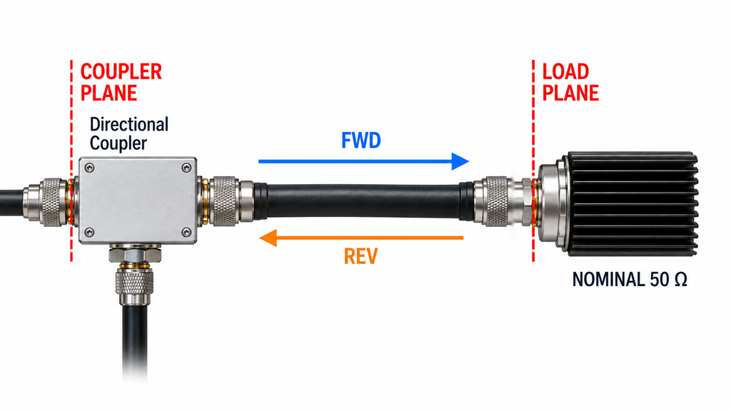
Nominally identical 50 Ω dummy loads do not guarantee identical impedances at the amplifier output plane. Frequency-dependent load match, cable and adapter characteristics, connector condition, and coupler placement affect the RF boundary seen during a retest.
A downstream cable may reduce load-end power while the coupler indicates a similar forward-power value upstream. Reflections may change the amplifier’s effective load and operating behavior; coupler readings can also be influenced by directivity and measurement-plane differences. Lower reflected power observed upstream of a lossy cable does not necessarily mean that the downstream termination has a better match.
For the disputed frequency, compare the actual load assembly and RF connection order, with calibrated FWD/REV or return-loss information where required by the test plan. A change in result after changing the RF path supports investigating that path, but does not by itself isolate one failed connector or cable.
If load rating, mismatch condition, or connection safety is uncertain, stop the powered test and use a suitable isolated evaluation. The full cable-qualification method belongs to the dummy-load cable testing guide.
5. Did DC Supply, Cooling, and Thermal State Change Between Tests?
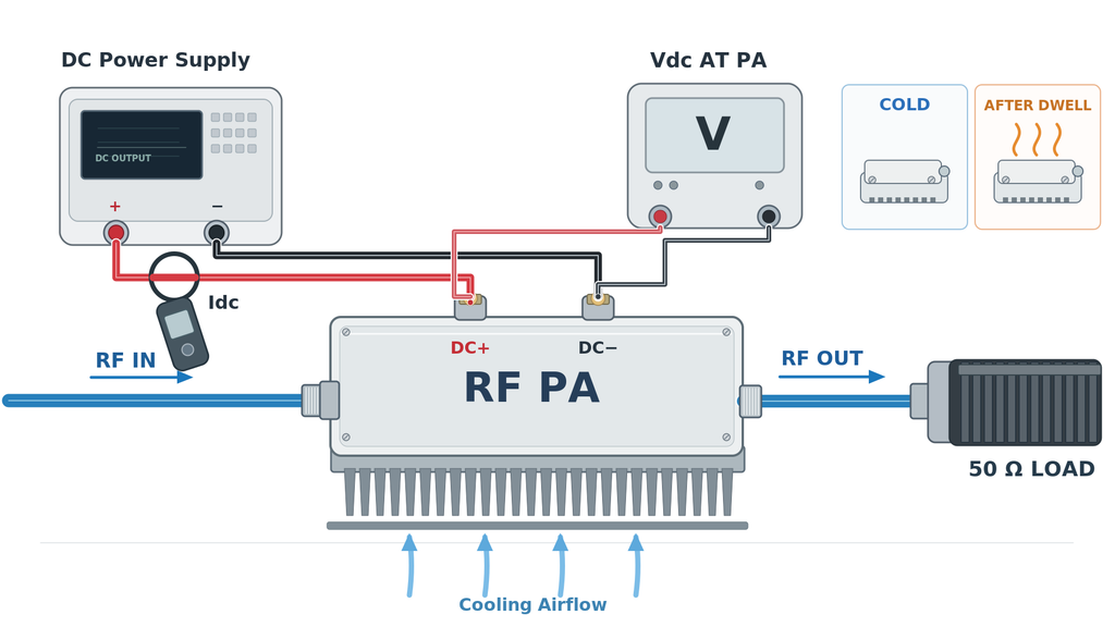
The PA may reach the customer lab in a different electrical or thermal state despite matching nominal frequency and drive settings.
Compare Vdc at the defined PA supply terminals under RF load—not just the power supply’s front-panel setpoint—together with Idc, current-limit behavior, relevant bias or enable state, and recorded protection activity. Voltage drop in the supply leads or a changed current limit may move the PA to a different operating point.
For thermal comparison, state whether each result was captured cold, during warm-up, after a specified fixed dwell, or after an agreed thermal stabilization criterion was actually met. A fixed operating time is valid evidence for that duration, but does not itself prove a stabilized hot state. Ambient conditions, heatsink or cold-plate contact, airflow, waveform duty cycle, and the temperature measurement location must be understood.
If the output changes primarily with operating duration or cooling, investigate a time- or temperature-dependent mechanism under controlled conditions. This observation does not by itself establish permanent damage. For sustained-temperature qualification, use the RF PA thermal-soak power verification procedure rather than treating a brief cold retest as equivalent.
6. Are the Power Meters, Calibrations, and Uncertainties Comparable?
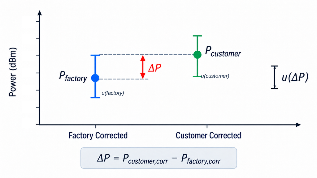
A sensor calibration certificate covers only part of the factory–customer measurement comparison. Calibration supports the instrument’s measurement validity within its applicable conditions; the complete setup adds its own uncertainty.
Review meter and sensor identification, calibration scope and applicability on the test date, frequency-dependent calibration factors, selected power metric, and instrument settings. Check the sensor’s operating range, linearity, zero or offset behavior, and possible overload—particularly where an attenuator or coupler shields a low-power sensor from a high-power PA. Coupler coupling uncertainty and directivity, path correction, mismatch, and repeatability may all contribute to the overall uncertainty.
After both reports have been aligned to the same measurand, reference plane, and comparable PA operating conditions, express their remaining difference as:
ΔP (dB) = Pcustomer,corr (dBm) − Pfactory,corr (dBm)
This signed difference shows which corrected reading is higher. It does not measure amplifier degradation by itself. Its interpretation requires an uncertainty associated with the difference, not merely a calibration date or a manufacturer’s standalone meter accuracy specification.
If the laboratories’ errors are independent, their uncertainty components may be combined using an appropriate measurement model. If they share a calibration reference, sensor, fixture data, or systematic correction, those contributions may be correlated; blindly treating them as independent can misrepresent the uncertainty of ΔP. Also consider whether the PA’s state could have changed between test dates, since an unstable test artifact cannot be separated from an instrument difference by a simple uncertainty calculation alone.
Evaluate the observed ΔP using a preselected comparison criterion and a credible uncertainty model. Check that the uncertainty contributions, correlations, sensor suitability, and observed repeatability are supported by evidence. An excessively broad or poorly justified uncertainty estimate can make results appear compatible while masking an unstable or inadequate measurement process. An apparently compatible result still requires a valid measurement method and a separate acceptance decision.
If the difference is explained by verified measurement conditions, document that explanation. If the uncertainty model, correlation assumptions, or comparison criterion is inadequate, record agreement not established rather than declaring the PA good or bad. No universal dB threshold applies to all RF PA retests.
Measurement Agreement Is Not the Same as Acceptance Conformity
Measurement agreement asks whether two results representing the same measurand are mutually consistent under an appropriate comparison method. Acceptance conformity asks whether a defined result satisfies a specified requirement, using the project’s applicable decision rule.
Two labs could agree closely and both measure below a required minimum. They could also disagree while each result remains on the same side of the specification limit; that still requires the discrepancy to be addressed according to the comparison objective and agreed acceptance process. Neither outcome makes measurement agreement a substitute for conformity assessment.
A minimum Pout requirement, measurement uncertainty treatment, guard band where applicable, and the authority to accept or reject must come from the relevant specification, contract, or approved test plan. Specify the rule before judging the disputed numbers.
For detailed evaluation of meter and sensor records, consult power meter calibration evidence verification.
7. What Controlled Retest Can Isolate the Source of the Difference?
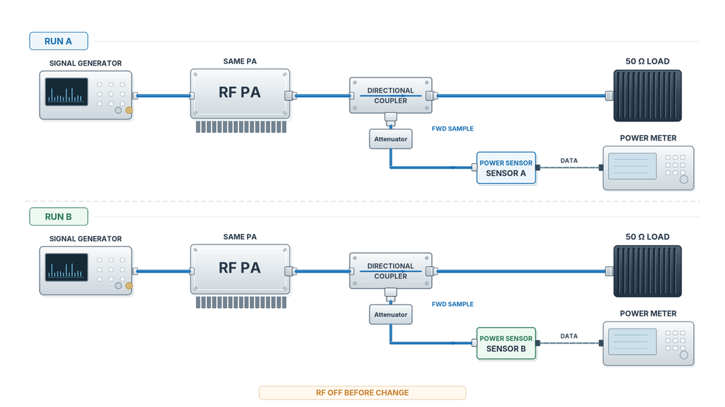
Design the joint retest to separate a repeatable difference from evidence of a specific cause. Simply rerunning both original setups may reproduce the disagreement without locating it.
Begin by documenting a common baseline: same PA and configuration, specified frequency and waveform, actual Pin, Pout measurement plane, load, Vdc/Idc boundary, cooling and thermal condition, correction settings, and power measurement metric. Establish short-term repeatability within each laboratory while those conditions are held constant. Then compare the corrected results between laboratories, recording which instruments, locations, operators, or procedures differed. One result from each lab supports an interlaboratory comparison, not a quantified claim of reproducibility. A formal reproducibility evaluation needs repeated measurements, specified changed conditions, and enough data to characterize dispersion.
The following hypothetical findings illustrate how to decide the next test; they are not RF SKYPOWER case results.
The discrepancy shrinks after reconstructing corrections. Suppose the factory value was corrected to the PA connector, while the customer’s report omitted a documented sampling-path correction. Recalculate only with the verified correction and its uncertainty. If the resulting gap is explained, document the reporting boundary and retain both raw datasets; do not claim that a numerical adjustment itself verified the PA.
The corrected values still differ, but actual Pin is not the same. Both reports may now represent PA-port Pout correctly, yet one laboratory used more RF drive or a different drive-control method. Align or explicitly characterize that operating-point difference within the authorized test range before comparing intrinsic output behavior. Do not compensate for an unverified Pin mismatch by adjusting the reported Pout arbitrarily.
The discrepancy persists after the critical conditions are aligned. First confirm that each laboratory can reproduce its own result. Then, where safe and metrologically appropriate, use an independently checked sensor or characterized path to investigate whether the difference follows the measurement channel, the test setup, or the PA’s operating state. A persistent difference warrants further investigation; it does not prove an internal PA defect without supporting isolation evidence.
Change only a controlled variable at a time when interpreting cause and effect, or use an explicitly designed comparison if several variables cannot be separated. Record before-and-after raw readings, applicable corrections, the conditions held fixed, and the uncertainty relevant to the comparison. A retest that changes cable, sensor, load, and cooling together may be useful for a functional check, but not for unique root-cause attribution.
Safety is a prerequisite. Confirm the frequency and average/peak power ratings and duty-cycle suitability of the load, coupler, attenuators, connectors, and sensors. Switch off RF output before rearranging high-power connections. A spectrum analyzer or vector network analyzer must not be exposed directly to PA output outside a specifically engineered, verified protection and attenuation arrangement; low-power VNA path checks require an isolated RF-off test state. Stop if load rating, reflected-power behavior, thermal condition, or protection status is unsafe or unknown.
The retest record should state whether the discrepancy recurred, which hypothesis the evidence supports or excludes, and what uncertainty remains. If the setup cannot be stabilized, that limitation is itself the result to carry forward.
8. When Should a Retest Discrepancy Trigger Further Investigation or an Acceptance Hold?
A power discrepancy should trigger more evidence when the measurements are not yet comparable, targeted isolation when its source remains uncertain, and a formal conformity decision only when the required evidence and decision rule are available.
The first four rows below describe measurement comparability and discrepancy attribution. The final row is a separate conformity check that may apply alongside any of them. These are not five mutually exclusive outcomes: a fully explained measurement difference can still lack a valid formal acceptance basis.
RF PA Power Discrepancy: Evidence and Disposition Matrix
| Current evidence status | Basis for judgment | What cannot yet be concluded | Next action |
|---|---|---|---|
| Not comparable yet | Different or unknown measurand, PA identity, reference plane, or essential operating state | Whether the PA itself lost output power | Stop direct number-to-number comparison; obtain definitions and establish a common test boundary |
| Partially comparable | Main conditions align, but material calibration, correction, or thermal evidence is incomplete | Whether the remaining difference originates in the PA or test system | Request the specific missing records or repeat the affected measurement |
| Comparable; discrepancy explained | Corrected records and controlled evidence identify a defensible cause | Whether unrelated contract acceptance requirements are satisfied | Document the explanation, retain raw data, and separately apply the agreed acceptance rule |
| Comparable; repeatable discrepancy remains unexplained | Relevant conditions align, but the difference persists without an adequate explanation under the agreed comparison method | Which internal or external component is responsible | Escalate a controlled engineering investigation without assuming an internal PA failure |
| Separate conformity check: acceptance basis incomplete | The applicable limit, decision rule, required evidence, or authority is undefined or unavailable, regardless of the measurement comparison state | An authorized pass, fail, or shipment-release status | Withhold that unsupported decision until the agreed acceptance basis is available |
A joint engineering investigation becomes appropriate when an unexplained difference persists under sufficiently controlled, comparable conditions, or when required measurement evidence cannot be reconstructed from either report. Before exchanging hardware or authorizing a return, the parties should agree on the specific unresolved question, the next safe measurement, and who will review the result.
For an RF amplifier acceptance test, an acceptance hold depends on the project’s approved decision process, not on a universal dB threshold. The contract or approved quality process determines who may place or release such a hold. If uncertainty or the required conformity rule is missing, the correct action is to withhold the unsupported conformity statement, without silently redefining the specification.
The transfer package for an unresolved dispute should connect the delivered PA’s S/N and relevant configuration to both dated datasets, raw and corrected values, frequency and waveform, actual Pin, reference-plane and correction records, load and instrument identities, calibration status, DC and thermal conditions, repeatability findings, and the agreed acceptance requirement. The next engineer can then review the outstanding measurement question without reconstructing either test from scratch.
If the issue becomes a broader shipment-release question rather than an isolated power-reading dispute, use the C-UAS RF PA acceptance checklist for the relevant unit-, batch-, configuration-, and project-level evidence. A result from one serial number or test condition should not be extended to other delivered units without an appropriate acceptance basis.
Conclusion
Different factory and customer power results do not, by themselves, establish an RF PA failure. The first defensible task is to confirm that both laboratories measured the same quantity at a common reference plane under comparable input, load, electrical, and thermal conditions. Only then can their corrected Pout difference be evaluated against suitable measurement evidence and uncertainty.
This comparison can reveal a reporting discrepancy, identify a condition that needs retesting, or support further investigation of the PA. It cannot set a universal acceptance tolerance, guarantee model suitability, or replace the approved project-specific conformity rule. Treating the gap between two displayed power values as amplifier degradation can lead to an unsupported rejection or repair decision.
The immediate engineering action is to exchange the original datasets, complete the comparability record, and agree on one controlled retest or missing-evidence request. Record the outcome and the responsible decision owner before any formal disposition.
For an RF SKYPOWER project-specific review, contact the RF engineering team and identify the PA model, S/N, configuration revision, test frequencies, waveform, reported power metric, and input/output reference planes.
Include both laboratories’ actual Pin, raw and corrected Pout, RF-path corrections, meter and sensor identities, calibration and uncertainty records, load and RF-path details, Vdc/Idc, cooling and thermal conditions, test duration, and applicable acceptance requirement or decision rule. The engineering review can then focus on the remaining discrepancy and the next verification step. Engineering review alone is not a formal acceptance decision or a guaranteed diagnosis.
If the investigation instead reveals that the project requires a different operating envelope or module configuration, the RF power amplifier module families provide a separate starting point for requirement-based product evaluation—not an automatic model recommendation from the disputed results.