











Coastal counter-unmanned aircraft system (C-UAS) sites need additional protection checks for their radio-frequency power amplifier (RF PA) installations. Coastal C-UAS RF module protection also requires checking salt deposits, humidity, condensation, and cabinet heat, because factory RF tests may not cover these installed conditions. An amplifier may meet its output-power specifications on a test bench while its installed connectors, grounding interfaces, cable entries, or cooling arrangement remain vulnerable to coastal exposure.
Coastal C-UAS RF module protection must account for the complete installation. A weather-sealed connector, conformal-coated circuit board, or ingress protection (IP) rating provides evidence about a particular component or protection boundary. The complete installation still needs to be assessed.
The required checks depend on site exposure, hardware configuration, and project acceptance criteria. Even a successful salt mist or humidity test cannot establish long-term reliability beyond its defined conditions.
Start by identifying the environmental stresses the equipment will face and the parts of the installation they can affect.
1. Why Does Coastal Exposure Require Additional RF Module Checks?
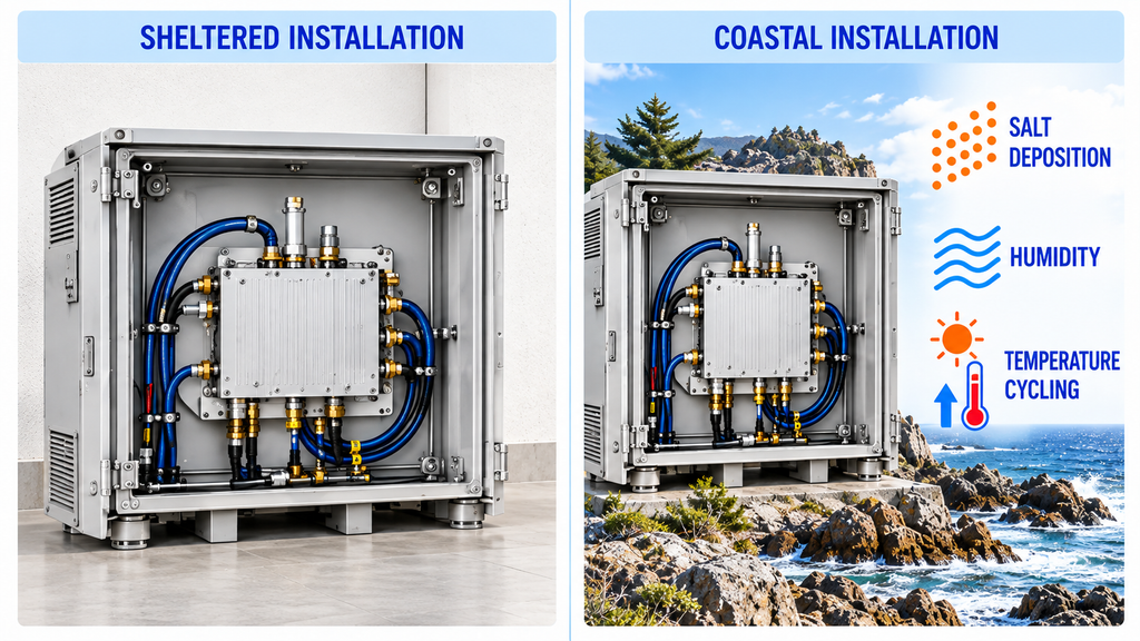
Coastal conditions expose RF equipment to stresses that may be absent from normal factory testing. Salt, moisture, and temperature changes affect different components through different mechanisms, so the verification requirements depend on the installation.
Salt deposition deserves particular attention around exposed connectors, cabinet hardware, cable terminations, and conductive joints. Airborne salt can accumulate on surfaces and, in the presence of moisture, contribute to corrosion or electrical leakage. The risk depends on the materials, protective finishes, contamination, and exposure conditions.
High humidity and condensation create different problems. Humid air does not necessarily produce liquid water. Condensation becomes possible when a surface cools below the dew point of the surrounding air, potentially wetting internal interfaces that have never been exposed to rain or sea spray.
Temperature cycling can make these conditions harder to control. Solar heating, amplifier power dissipation, overnight cooling, and shutdown periods change internal temperatures. Where seals or cable entries are imperfect, temperature and pressure changes may also contribute to moisture exchange.
Fixed outdoor C-UAS sites can face several of these conditions in the same installation. Depending on the system design, RF equipment may operate for extended periods inside remote cabinets with multiple RF channels, external feeders, shared cooling, and remote monitoring.
Consider the same RF PA installed at two sites. One operates inside a sheltered cabinet with controlled temperature and moisture. The other uses outdoor cable entries near exposed coastal infrastructure and experiences repeated shutdown and cooling cycles. The module specifications are identical, but the environmental evidence needed for the two installations may differ substantially.
The exposure mechanism determines which checks matter most.
Where direct spray or salt deposition is expected, the review should focus on exposed metals, connector assemblies, cable entries, corrosion protection, and applicable salt-exposure evidence. Testing a connector material alone does not establish the condition of the assembled outdoor connection.
Where humidity and shutdown-related condensation are the main concerns, attention shifts to internal moisture control, condensation-sensitive interfaces, and the conditions used for functional testing. A salt spray report cannot substitute for evidence addressing condensation.
If solar heating, high ambient temperature, or prolonged RF operation creates additional thermal stress, the cabinet’s cooling arrangement also needs verification. Changes made to improve sealing may alter the conditions under which earlier thermal results were obtained.
The integrator should document the site’s exposure, equipment location, operating and shutdown states, cabinet configuration, and maintenance conditions before selecting the required verification methods.
Without that information, a generic outdoor rating provides too little basis for deciding whether the coastal protection requirements have been met.
2. What Should Be Checked at RF Connectors, Coatings, and Grounding Interfaces?
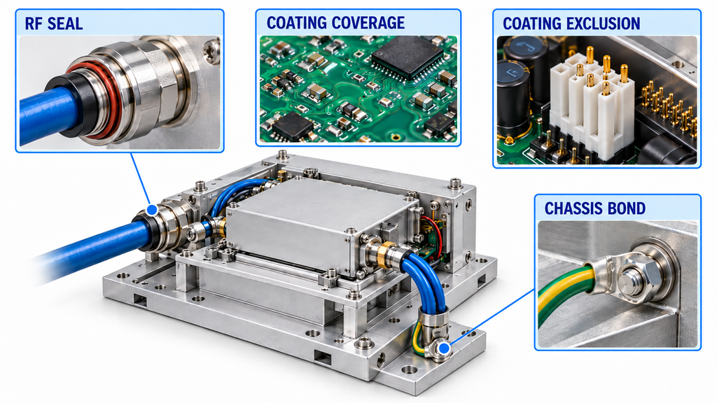
Moisture and salt contamination can affect several electrical and mechanical interfaces within the same RF installation. Each needs to be examined according to its function and exposure.
Connector sealing, board-level coating, and cabinet protection address different failure paths. A satisfactory result for one does not establish the condition of the others.
Connector, Cable Entry, and Seal Boundaries
Inspect the installed RF connection from the cable termination through the mating interface and cabinet entry. Relevant details include connector compatibility, mating condition, sealing elements, cable support, bulkhead feedthroughs, and drainage arrangements.
A correctly specified connector can still be exposed if its installation allows water to collect around the cable entry or places excessive mechanical load on the mating interface.
DC power and control connections need attention as well.
Corrosion or unstable contact in a DC connection may increase voltage drop or interrupt supply continuity. Moisture entering a control interface may disrupt command or status signals, potentially contributing to intermittent communication or alarm behavior.
RF connections present additional measurement concerns. Contamination, plating damage, or unstable contact can change insertion loss and reflection characteristics.
A reflected-power alarm does not necessarily identify an internal PA fault. Moisture or corrosion in an external connector, feeder, or antenna-side connection may change the load presented to an otherwise functioning amplifier. In that case, the PA’s protection circuit may be responding correctly to an external problem.
Visual inspection helps locate damage, but electrical performance must be evaluated separately where the project requires it.
The detailed procedure for preventing water ingress in RF PA connectors covers connector-level inspection and repair. Coastal deployment verification must also account for the remaining installed RF path.
PCBA Coating Coverage and Excluded Areas
Conformal coating can protect selected board surfaces against moisture and contamination when the material and application process suit the design.
The integrator should establish which areas were coated, which were deliberately excluded, and how the completed printed circuit board assembly (PCBA) was inspected.
RF-sensitive interfaces, grounding contacts, connector mating areas, test points, and thermal surfaces may require controlled exclusions. Coating these areas unintentionally can interfere with electrical contact, RF behavior, servicing, or heat transfer.
Hardware revision matters too. A coating record for one board configuration may not adequately describe a revised assembly with different components or exposed interfaces.
The RF PA conformal coating process provides further detail on manufacturing and inspection.
For coastal deployment, the relevant question is whether the documented coating configuration protects the required board areas without compromising electrical or thermal functions.
Board-level coating does not eliminate the need to protect external connectors, cable entries, and the enclosure.
Bonding, Fasteners, and Corrosion-Sensitive Joints
Grounding and mechanical joints deserve separate inspection because corrosion can compromise electrical continuity and mechanical integrity.
Check mounting hardware, chassis bonds, shielding contacts, cabinet joints, and conductive interfaces that form part of the electrical or RF return path.
Material combinations, protective finishes, contact pressure, and exposure affect the potential for degradation. Corrosion, damaged surfaces, loose fasteners, or unstable contact may call for further investigation.
Electrical checks must match the function of the joint. A low DC resistance reading can support a continuity assessment without establishing acceptable high-frequency bonding behavior.
The inspection should leave no uncertainty about who is responsible for each protection boundary: the module manufacturer, connector or cable supplier, cabinet manufacturer, or system integrator.
Where an interface’s installed condition is unknown, specifications for an adjacent component cannot establish its protection.
3. How Can Sealed RF Cabinets Control Moisture Without Losing Cooling Margin?
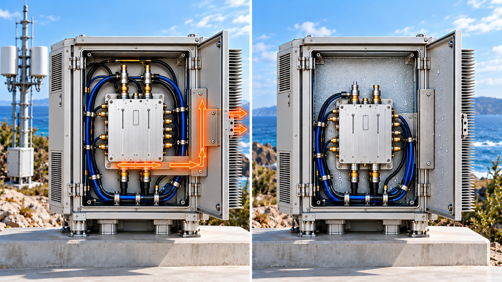
A tighter cabinet seal may reduce moisture entry while making heat harder to remove. Both effects need to be evaluated in the installed configuration.
RF cabinets use different cooling arrangements, including conductive heat transfer through mounting surfaces, external heat exchangers, controlled ventilation, and filtered airflow. Each creates different conditions for moisture control and heat dissipation.
An IP rating describes protection against specified access, solid-object, and water-ingress conditions. It does not establish salt-corrosion resistance, prevent condensation inside the enclosure, or demonstrate sufficient cooling.
Even a well-sealed cabinet can contain moisture introduced during assembly, previous exposure, or maintenance. If an internal surface cools below the local dew point, condensation may occur without water entering from outside.
Cooling changes can create another problem. An amplifier that meets its thermal requirements in an open laboratory setup may operate at a different temperature inside a sealed cabinet.
For a fixed C-UAS installation, the assessment should reflect the equipment actually installed. Multiple RF channels or other heat-producing devices may share the enclosure. Active operation, standby, shutdown, and restart can also produce different temperature conditions.
A sealing modification is therefore a reason to review the thermal evidence.
For example, replacing a ventilated cabinet with a more tightly sealed design may reduce an external moisture path but change the internal heat-transfer arrangement. Temperature measurements from the original configuration may no longer apply.
The revised setup should be assessed using its actual cabinet configuration, ambient or inlet temperature, RF operating condition, duty cycle, supply, mounting arrangement, measurement locations, and the duration required to evaluate thermal behavior.
The RF power amplifier guide for 50°C sites covers high-temperature selection in greater detail.
For coastal deployment, moisture protection and cooling must both satisfy the requirements applicable to the final installation. If the enclosure changes materially after testing, the earlier evidence needs to be reviewed before it is used to support approval.
4. Which Salt Mist, Humidity, and Ingress Tests Provide Relevant Evidence?
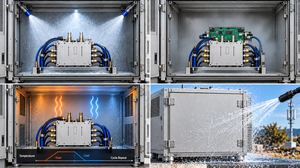
Environmental tests must match the exposure mechanism and the hardware being evaluated. Salt mist, steady-state humidity, cyclic humidity, and water-ingress testing provide different evidence.
IEC 60068-2-52:2017 specifies cyclic salt mist test methods for components or equipment exposed to salt-laden atmospheric conditions. The result depends on the selected method, specimen configuration, exposure conditions, and acceptance criteria.
ISO 9227:2022, together with applicable amendments, describes salt spray methods for evaluating metallic materials and corrosion-protection systems. Its results cannot be directly converted into expected field lifetime or used as a universal ranking of corrosion performance across different materials.
A successful test on a coated metal sample, for example, does not establish the environmental reliability of a complete operating RF amplifier.
Humidity testing requires a different distinction.
IEC 60068-2-78:2025 addresses steady-state damp heat at constant temperature under non-condensing conditions.
IEC 60068-2-30:2025 covers cyclic damp heat involving temperature changes and generally associated condensation.
Results from a non-condensing humidity test do not establish behavior during condensation-producing cycles. A cyclic damp heat result also does not address every failure mechanism associated with salt contamination.
IEC 60529 defines degrees of protection provided by enclosures against specified access, solid-object, and water-ingress conditions. It is not a general corrosion-resistance or service-life standard.
After selecting the applicable test, examine the report itself.
An RF amplifier environmental test report should identify the specimen and hardware revision, test procedure and exposure conditions, whether the equipment was powered, any recovery requirements, the evaluation method, acceptance limits, and findings.
The assembly level is especially important. A material coupon, connector, coated PCBA, complete RF module, and outdoor cabinet have different verification boundaries. Their results cannot be transferred freely between those levels.
The installed configuration may also differ from the tested specimen. Adding cable glands, modifying bulkhead connectors, or changing cabinet ventilation can affect whether earlier results remain applicable.
A specified number of salt mist test hours cannot be converted into a guaranteed number of coastal service years.
If a report does not establish the specimen, conditions, or acceptance scope relevant to the project, the affected requirement remains unverified. Additional evidence is needed before that result can support the deployment decision.
5. How Should RF Modules Be Retested After Salt or Humidity Exposure?
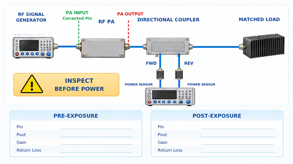
Post-exposure RF verification depends on the specimen’s condition, a comparable electrical baseline, and defined acceptance limits. A normal output-power reading means little when the conditions behind it are unclear.
Begin by recording the specimen’s condition after exposure.
The record should establish whether the equipment was powered during exposure, when exposure ended, what recovery period followed, and whether cleaning, drying, resealing, or repair occurred before testing.
These details affect what the result can prove.
A connector tested immediately after exposure may behave differently from one tested after recovery. If its RF performance returns to normal after cleaning and resealing, the later measurement supports the repaired condition. It does not establish that the original moisture-exposed connection passed.
Safety takes precedence over preserving the as-exposed condition. Visible moisture, corrosion, insulation damage, or compromised connectors must be assessed before powered testing. An unsafe assembly should not be energized merely to obtain a comparison measurement.
The electrical comparison then needs consistent operating and measurement conditions.
Pre-exposure and post-exposure records should identify the hardware configuration, test frequency, waveform, duty cycle, actual input power (Pin), output power (Pout), supply voltage and current, load, cooling arrangement, and relevant thermal state.
RF measurement reference planes and path corrections are essential.
The signal generator setting may differ from the actual power delivered to the PA input. Likewise, output power measured at the amplifier connector cannot be compared directly with power measured after additional feeder loss unless those measurement locations and corrections are reconciled.
Forward and reflected power, or voltage standing-wave ratio (VSWR), must be evaluated using a suitable directional measurement arrangement with appropriate calibration or correction. Raw instrument readings and values corrected to a specified reference plane should remain distinguishable.
Thermal and frequency coverage matter as well. A cold-state result does not replace required stabilized hot-state evidence, and a single-frequency measurement cannot demonstrate compliance across an entire operating band.
A change in output power is not convincing evidence of environmental degradation if differences in test conditions or measurement uncertainty can account for it. Where comparability remains incomplete, the report should identify the limitation rather than assign a definite cause.
The next question is whether the observed behavior originates inside the PA or elsewhere in the installation.
Moisture or corrosion in a bulkhead connector, feeder, or antenna-side connection may alter the load presented to the amplifier. A reflected-power alarm under those conditions may represent normal protection behavior.
Where the approved procedure permits, compare module operation with an appropriate controlled load against its behavior with the installed RF path. Such testing requires proper isolation and measurement protection. Instruments must never be exposed to high-power connections beyond their ratings.
Supply instability, control faults, temperature alarms, and protection recovery may also require separation of module-level behavior from integration problems.
For remote C-UAS installations, alarm timestamps can help relate abnormal operation to rainfall, humidity changes, shutdowns, or restarts. Those relationships guide investigation but do not establish a root cause without supporting measurements.
A post-exposure RF amplifier test report should identify the specimen’s condition, any recovery or corrective actions, the measurements performed, the acceptance limits, and the conclusions supported by the results.
For delivered-unit traceability and broader shipment evidence, see the C-UAS RF PA acceptance checklist.
6. What Evidence Supports Coastal Deployment Release and Maintenance?
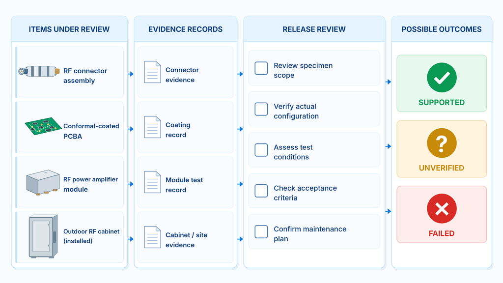
Deployment approval depends on whether the available evidence addresses the specified environment, hardware, installation, and acceptance limits.
A connector test may support a particular connector assembly. A coating inspection applies to the specified PCBA. A cabinet test addresses the enclosure configuration used during testing. Each result contributes to the deployment review within its defined scope.
The following matrix links common coastal risks to the evidence and responsibility needed for verification.
Coastal Environmental Protection Verification Matrix
| Inspection area | Protection or installation boundary | Evidence to review | Applicable scope or responsible party | Action if evidence is insufficient |
|---|---|---|---|---|
| Salt exposure and corrosion | Exposed metals, joints, contact finishes, fasteners | Material specifications, corrosion tests, inspection findings | Tested component or assembly; responsible supplier | Obtain protection evidence for the relevant exposure and configuration |
| RF, DC, and control connectors | Contacts, seals, terminations, cable entries | Connector data, installation checks, electrical results | Module interfaces and installed connections; supplier or integrator | Inspect and verify the affected interfaces |
| PCBA conformal coating | Coated areas, exclusions, sensitive interfaces | Process records, coverage inspection, functional results | Specified PCBA revision; module manufacturer | Confirm coating coverage and revision applicability |
| Cabinet sealing and condensation | Enclosure joints, glands, vents, internal moisture | Ingress evidence, installed configuration, moisture assessment | Completed enclosure; cabinet supplier and integrator | Check whether test evidence covers the as-built cabinet |
| Cooling and thermal operation | PA mounting, heat path, airflow, temperature sensing | Temperature, operating, and protection records | Installed cooling system; assigned responsible party | Verify thermal behavior in the final configuration |
| Post-exposure functionality | RF, DC, control, grounding, protection | Comparable test records, specimen condition, acceptance limits | Tested specimen or delivered unit, as required | Complete the required verification before release |
The matrix identifies what must be verified. It contains no measured results for a particular product.
A requirement supported by evidence matching the approved configuration, test conditions, and acceptance limits can proceed to the next applicable approval step. That does not by itself approve the entire installation.
Missing or mismatched evidence leaves the affected requirement unresolved. The project team may need additional documentation, inspection, analysis, or testing.
A measured failure to meet a mandatory acceptance limit calls for the project’s agreed corrective-action, retest, or release-hold procedure. An unverified requirement and a demonstrated failure must remain separate findings.
Traceability adds another distinction.
A representative RF amplifier reliability test that includes the required environmental exposure may support a defined design or configuration when its specimen scope and acceptance criteria meet the project’s qualification requirements. It does not establish that every delivered RF PA underwent the same exposure.
A serial-number-linked functional report, meanwhile, documents results for an identified unit under recorded conditions. The report cannot establish the environmental protection of an outdoor enclosure unless that configuration and requirement were also evaluated.
Installation changes may affect earlier verification. Replacing connectors, modifying cable glands, changing cabinet seals, or altering cooling can require reassessment of the affected boundaries.
Maintenance should respond to the site’s exposure and observed condition. Corrosion, damaged seals, unexplained alarms, moisture intrusion, and equipment modifications can trigger additional checks. Remote monitoring may reveal unusual behavior between physical inspections, although alarm data still needs engineering interpretation.
Inspection intervals should follow the project’s approved maintenance requirements and risk assessment. There is no universal coastal inspection period suitable for every RF installation.
The release record should identify which requirements are supported, which remain unresolved, who owns the outstanding work, and which approval decisions can proceed.
What Should Integrators Specify in a Coastal C-UAS RF Module RFQ?
A coastal C-UAS RF module request for quotation (RFQ) should describe the intended environment and installation in measurable terms. A request for “marine-grade protection” alone leaves the supplier without enough information to determine the required evidence.
The environmental requirements should identify equipment location, expected salt and moisture exposure, operating and storage temperatures, condensation conditions, cabinet design, and maintenance constraints.
RF requirements should define the frequency range, waveform and duty cycle, actual input power, required output power and reference plane, load, DC supply, control interfaces, cooling arrangement, and relevant protection behavior.
Where environmental verification is required, specify the test method, specimen configuration, acceptance criteria, and expected evidence. Separate the requirements for materials, connectors, PCBAs, RF modules, enclosures, and the installed system.
Responsibility must be explicit.
The RF module supplier may provide evidence for a defined hardware configuration, while the system integrator remains responsible for external cable entries, cabinet sealing, installed grounding, and the completed cooling arrangement.
The RFQ should also distinguish design qualification, configuration or batch evidence, serial-number-linked functional records, and final site acceptance. Requiring traceable measurements for delivered units does not mean repeating every environmental qualification test on each amplifier.
For broader frequency, power, and integration decisions, the C-UAS RF power amplifier module selection guide provides the relevant framework. Integrators can review available RF power amplifier module families before requesting a project-specific evaluation.
A product’s presence in a catalog does not establish its suitability for the coastal installation.
The supplier and integrator should be able to identify which requirements have supporting evidence, which depend on final integration, and which still require testing. Specific model suitability remains conditional until the applicable evidence has been reviewed.
Conclusion
Coastal C-UAS installations need additional RF module protection checks wherever salt, moisture, condensation, or cabinet heat creates conditions beyond those covered by routine factory RF testing.
The checks help establish whether connectors, grounding interfaces, coatings, enclosures, cooling, and RF functionality meet the project’s defined requirements. They cannot establish a particular module’s environmental qualification, guaranteed service life, or complete system acceptance without corresponding evidence.
A salt mist report, IP rating, or coating record supports its specified test or inspection boundary. The final installation needs its own applicable evidence and acceptance decision.
Before deployment, the integrator should identify the relevant environmental risks, check the evidence for each affected component or assembly, and resolve outstanding verification requirements with the responsible parties.
For a project-specific evaluation, contact RF SKYPOWER with the site’s environmental conditions, required frequency range, waveform and duty cycle, actual input and output power conditions, measurement reference planes, DC supply and load requirements, connector and cabinet configuration, cooling arrangement, and required environmental and functional test evidence. This information allows the engineering review to establish which requirements can be supported and which still need verification.