










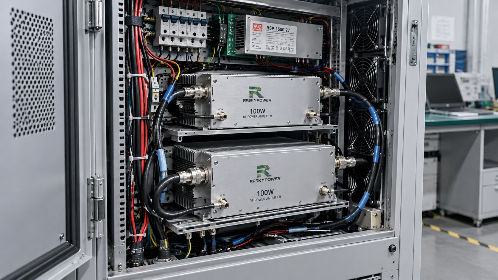
A space-limited C-UAS cabinet layout may accommodate an RF power amplifier (RF PA) on paper yet leave too little room to connect, cool, or remove it. Mating connectors, RF and DC cables, control plugs, and maintenance access all need space beyond the module body.
The listed dimensions of RF power amplifier modules are a starting point. A PA placed beside a cabinet wall may leave no room for its RF output cable to turn. Moving it can clear the cable while blocking a cooling inlet or another module’s wiring.
Before approving the layout, engineers need to check the full installation envelope and whether the assembled cabinet can meet each requirement under its specified operating conditions.
1. What Must Fit Beyond the RF PA Module?
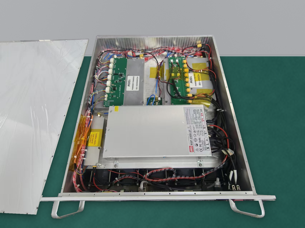
The cabinet needs room for the mounted PA, its connections, and the work required to install and service it.
Check the mounting arrangement, heatsink, fasteners, RF connectors, DC terminals, control plugs, and cable exits against walls, shelves, cable channels, and neighboring modules. Use the intended mating hardware and applicable assembly tolerances rather than nominal dimensions alone.
For example, a PA may fit between rails while its mated RF connector enters occupied space. It may be impossible to tighten the connector or route the cable within the manufacturer’s bend limits. The installed envelope includes mating length, any specified straight cable exit, and assembly-tool access—not just the PA outline.
During operation, connections and cooling paths must remain usable. During maintenance, technicians may need access to fasteners and connectors and a clear route for withdrawing the module. These clearances can overlap when tasks occur at different times, provided each task can be completed in the final assembly.
In a multi-PA cabinet, clearing one amplifier’s connector may obstruct another module’s cable or cooling path. Check the assembled layout, not just individual module footprints.
Amplifier efficiency affects heat generation and C-UAS cabinet sizing. In a cabinet with fixed dimensions, the immediate task is to fit the chosen hardware and its connections into the available space.
Before freezing placement, compare module specifications and drawings with the actual mounts, mating connectors, cable assemblies, and clearances. Missing interface details or relevant assembly tolerances make the fit decision premature.
2. How Does Restricted Airflow Change RF PA Placement?
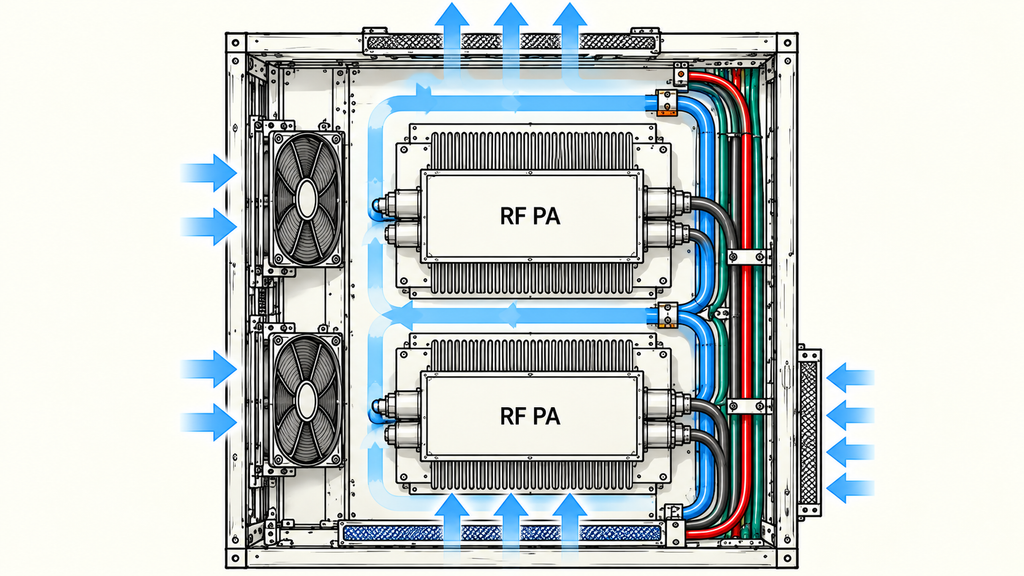
A fan’s rated airflow does not establish how much air reaches the PA after installation. The inlet, exhaust path, internal resistance, neighboring equipment, and cooling structure all affect that flow.
Limited space may place amplifiers close together or force cable bundles near a heatsink. Rotating a PA can free room for its RF output connector while changing the relationship between the heatsink and the intended airflow. Routing a harness across an inlet can add another restriction.
Both changes may be workable, but the original cooling assessment may no longer apply. The revised airflow path still needs to support the specified operating load.
Assess cooling with the intended cable bundles, filters, cooling equipment, nearby heat sources, and closed doors where applicable. Compare thermal results under relevant RF loads, ambient temperatures, and cooling settings. An open-door temperature reading does not verify closed-door operation.
If moving the PA changes the cabinet airflow path, check whether the existing cooling evidence still applies. Until evidence covers the new route, cooling remains unverified even if the RF connector now has enough room.
The layout review must therefore decide whether to retain the position, change the cooling arrangement, or hold the affected approval for further verification.
3. What Clearance Do RF Cables and Connectors Need?
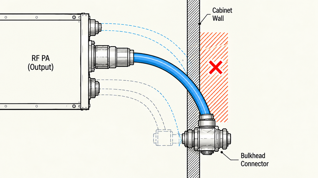
RF cable routing often becomes difficult immediately outside the PA connector, where the cable turns toward its next interface.
A drawing may show a clean line between the PA and a cabinet feedthrough. The installed assembly needs room for the mated connector, cable diameter, permitted bends, and supports.
A wall too close to the output connector can force the first bend against the connector body. That may stress the assembly and affect RF performance. A line that clears the wall in a drawing does not establish that the mated connector and cable will fit.
There is no universal bend radius for RF cables. Limits depend on construction and manufacturer requirements; some assemblies distinguish an installation bend from repeated flexing during service. The required initial straight section, if any, must also come from the selected assembly’s specifications rather than an assumed universal dimension.
Check the selected connector’s mating dimensions, cable exit direction, first permitted bend location and radius, support points, and access for connection or removal. Include cabinet doors, partitions, and neighboring cables.
Two routes that look alike may perform differently with different cables or connectors. RF cable bending and connector stress can affect mechanical fit and RF performance.
If the cable specification or mating connector dimensions are missing, leave the route undecided. Those details may require moving the PA or choosing another cable assembly.
4. How Do DC and Control Paths Compete for Space?
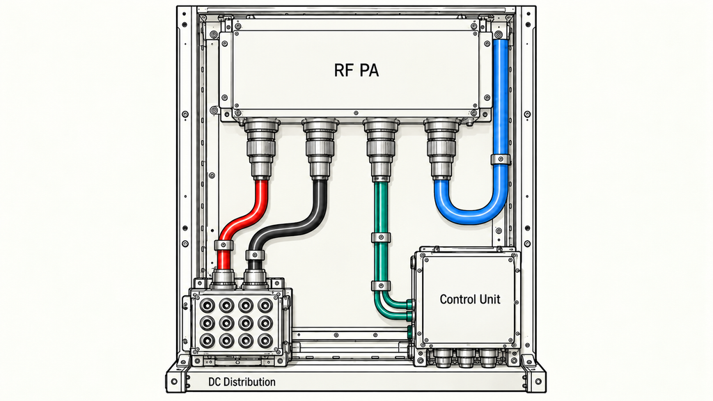
DC and control wiring competes with RF cables, cooling, and service access for cabinet space. A supply-and-return pair drawn as two lines becomes insulated conductors with connectors, fastening points, and routing restrictions.
For an RF PA designed for a nominal 28 V DC supply, the wiring must support the specified load. The source’s nominal voltage alone does not establish the voltage available at the PA terminals under load.
Two checks matter.
First, the supply and return conductors need an installable route from the distribution point to the PA, with room for connections, supports, and any required protection hardware.
Second, the electrical design must meet the PA’s operating requirements. A wire may fit through a narrow channel yet be unsuitable for the required current or voltage drop. A conductor sized for that load may be too large or stiff for the route.
Control interfaces create similar conflicts. A plug may be accessible before nearby RF cabling is installed but impossible to disconnect afterward. Its mating direction, cable exit, and required service access need to be evaluated as part of the complete harness arrangement.
Check the proposed layout against the module’s DC supply requirements, the actual wiring configuration, and the specified operating load. Mechanical fit does not verify electrical suitability, and adequate supply capacity does not prove that the wiring can be installed.
If supply conditions, connector arrangements, or operating loads are undefined, keep the affected decision open. Shared-DC-bus behavior, protection coordination, and control timing need separate evaluations; this layout check concerns whether the physical connections fit without blocking other cabinet functions.
5. Can the PA Be Serviced Without Reworking the Cabinet?
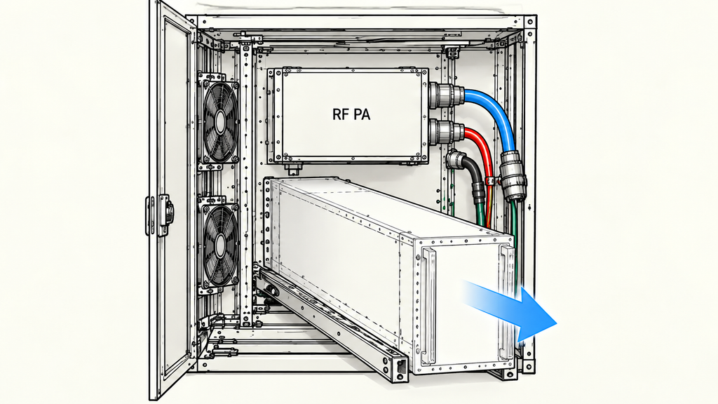
An RF PA can operate normally yet be hard to inspect or replace. In a crowded cabinet, access for prescribed maintenance tasks can determine whether the installation remains practical over its service life.
A PA mounted behind another assembly may have accessible RF connectors during installation, then lose access to its mounting screws once surrounding hardware is secured. Replacement could require removing neighboring components.
Whether that sequence is acceptable depends on the project’s maintenance requirements and permitted work conditions. Review the planned maintenance tasks, not just the installation sequence.
Can the technician reach the necessary fasteners and connectors with the required tools? Can RF and DC connections be safely disconnected using the specified maintenance procedure? If the PA must be removed, is there a workable withdrawal path in the assembled cabinet?
Also check access to filters, fans, and other serviceable cooling components. A PA mounting position or cable bundle that is mechanically acceptable for operation may prevent these items from being serviced.
In correctional facilities and other high-security installations, restricted maintenance access or an approved service window may make these constraints especially relevant. Those restrictions must be taken from the project requirements, not assumed from the facility type.
Mechanical drawings can reveal likely conflicts, but an assembled-unit demonstration may be needed to verify a removal or replacement task. A connector reachable during assembly may be blocked once neighboring hardware is installed.
Being able to remove a module does not establish hot-swapping, replacement without shutdown, or a guaranteed repair time. Those capabilities require separate system provisions and evidence.
Before approval, define the necessary maintenance tasks and confirm their access paths. An obstruction may require a mounting change, a different approved service procedure, or a further assembly check.
6. How Should Integrators Approve a Space-Limited Layout?
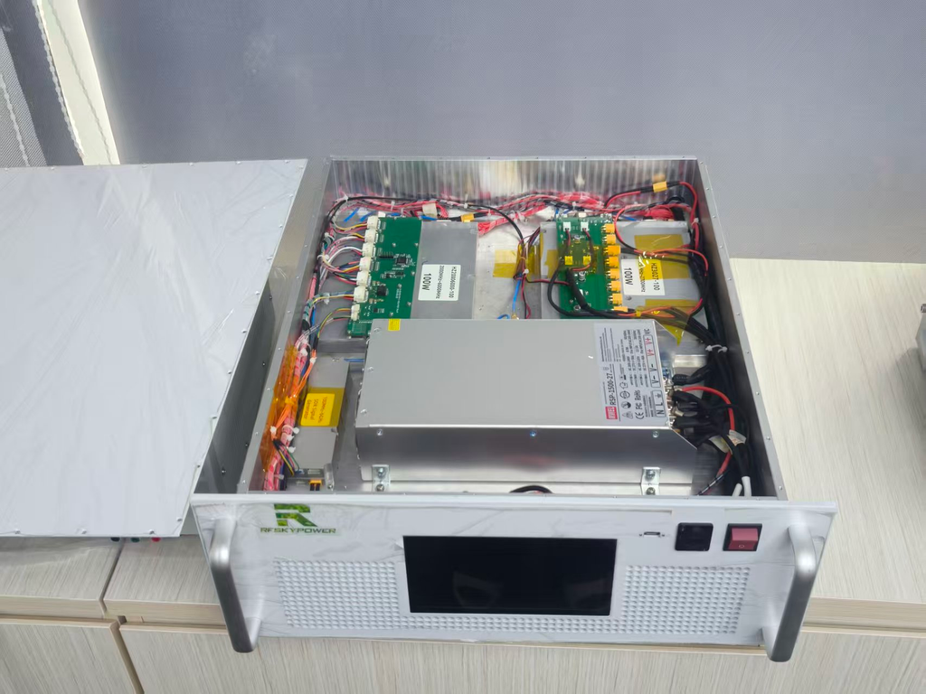
When integrating RF power amplifiers into a C-UAS system, engineers need to review the full layout because fixing one clearance problem can invalidate another part of the assessment.
Moving a PA may improve RF connector clearance but restrict cooling. Rerouting a cable may open a service path but violate its bend limits. Relocating DC distribution hardware may simplify wiring but block component removal. Each change affects the layout as a whole.
The Space-Limited Cabinet Integration Review Matrix identifies the key constraints, supporting evidence, and actions when a requirement fails or remains unverified.
| Constraint Category | Required Check / Boundary | Evidence Needed | Action if Unmet |
|---|---|---|---|
| Installation Envelope | Module, hardware, connectors and obstructions | Mechanical drawings and assembly checks | Revise confirmed interference; hold if fit is unverified |
| Cooling | Inlet, heatsink, exhaust and nearby heat sources | Actual cooling configuration and thermal evidence | Revise a failed configuration; hold if unverified |
| RF Routing | Connector access, cable bends, support and entry paths | Cable specifications, routing drawings and assembly checks | Revise a conflicting route; hold if specifications are missing |
| DC and Control | Power return paths, distribution, connectors and harnesses | Wiring drawings, interface limits and load conditions | Revise a failed route or design; hold if unverified |
| Service Access | Tools, disconnection, removal and replacement | Service-clearance drawings and access demonstration | Revise inaccessible tasks; hold if unverified |
| Operating Verification | Defined operation with the cabinet in its installed configuration | Records under specified operating conditions | Hold required acceptance if unverified; revise if failed |
The matrix sets no universal clearance limits, thermal thresholds, or acceptance values. A confirmed interference or performance failure calls for a design or procedure change. Missing evidence leaves the affected decision on hold; it does not establish that the PA has failed.
In a multi-PA C-UAS cabinet, moving one module to clear its RF output connector may push a neighboring harness across another module’s cooling inlet. Recheck the RF route in the revised assembly. Cooling remains unverified until the evidence covers the new airflow path and, where required, simultaneous PA operation. The preliminary layout may advance with that item open only if the current review gate permits it; the cooling arrangement must not be described as verified.
Drawings show planned clearances and possible interference. Assembly checks confirm whether the specified connectors, cables, and fasteners can be fitted and reached. Operating records assess performance under defined conditions. Each answers a different question.
Physical fit does not verify closed-door cooling, and a module-level RF output result does not establish performance at a downstream cabinet interface.
Where operating verification is required, use the specified installed configuration and load. Relevant records may include temperature at defined locations, DC voltage at the PA terminals, RF output at a clearly identified reference plane, and applicable protection or alarm behavior.
Record the measurement reference plane: power at the PA output connector may differ from power at a downstream interface after cable and connector losses. Compare layouts directly only when equipment, loads, cooling conditions, and measurement methods are sufficiently aligned. Otherwise, assess the results separately.
Record the approval stage and the checks it requires. If they pass, the layout can advance. A confirmed physical conflict calls for revision and another check; missing evidence required at that stage keeps approval on hold. Early layout approval is not final acceptance of the assembled system.
An unresolved item may reflect missing data or a cabinet-level conflict rather than an unsuitable PA. The supplier can provide module specifications and interface information; the integrator remains responsible for assessing the assembled cabinet against the project’s installation, operating, and maintenance requirements.
Conclusion
In a space-limited C-UAS cabinet, cooling paths, RF and DC cables, control access, and maintenance all compete for room. The PA’s outside dimensions alone cannot establish whether the installation will fit and operate as required.
A layout can advance when it meets the checks required at the current design stage and records any remaining verification work. Final system acceptance needs evidence from the specified assembled configuration under its operating conditions. A smaller PA may free space without solving every connector, cable, cooling, or service conflict. The matrix helps identify those conflicts, but model-specific clearances, thermal limits, electrical acceptance criteria, and final approval values still require technical data.
Before freezing the layout, compare the actual mounted hardware and mating interfaces with the available clearances. Check installation and removal paths, finish the current design-stage review, and list operating verification still outstanding.
For a project-specific RF PA configuration review, contact the RF SKYPOWER engineering team. Provide cabinet dimensions, PA quantity and mounting orientations, frequency range, required RF output power, and operating duty. Include the cooling arrangement, RF cable and connector specifications, DC distribution, control interfaces, maintenance requirements, and planned verification conditions.