










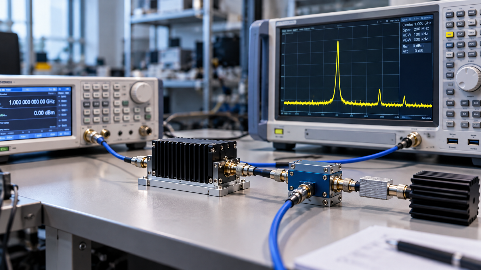
An RF amplifier spurious output test should not begin by replacing the power amplifier. First measure the source baseline at the defined PA input reference plane, verify that the spectrum analyzer is not creating the unwanted line, then reinsert the PA and compare the same spectral component under matched frequency, waveform, Actual Pin, load, thermal state, and analyzer conditions.
A spur seen before the PA shows that the source chain contributes to that frequency component; it does not prove that the PA has no effect on its final level. A spur that appears only after the PA is inserted is stronger evidence of PA or RF-path involvement, but it is still not a confirmed PA fault until analyzer distortion and setup-dependent coupling have been reasonably excluded. A single output screenshot can otherwise trigger an unnecessary module replacement or an incorrect supplier rejection.
The test should establish where the spectral line first appears, how it changes when one controlled variable changes, and which alternative explanations remain open.
1.Define the Reference Planes Before You Blame the PA
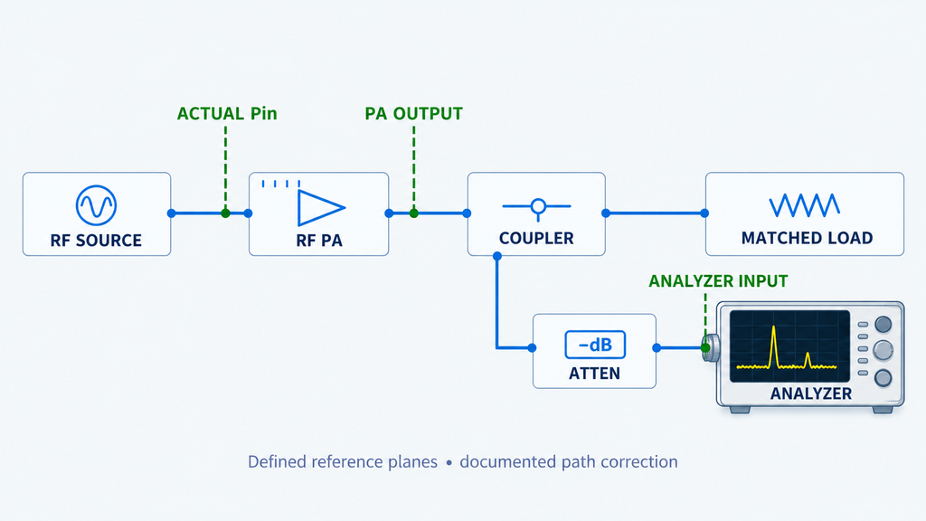
A meaningful source-versus-PA comparison needs named measurement planes. At minimum, distinguish the source-chain output or defined PA input reference plane, the defined PA output reference plane, and the spectrum analyzer input. If a coupler, cable, attenuator, filter, switch, or adapter sits between those points, record whether its loss or coupling factor is already included in the displayed result.
Actual Pin means the RF power at the defined PA input reference plane after the applicable source-path correction. It is not automatically the signal generator display setting. Likewise, a spectrum reading at the analyzer input is not automatically a corrected result at the PA output unless the output sampling path and correction terms are defined.
Before comparing spectra, hold constant the conditions that can change the interpretation: frequency, waveform, Actual Pin, load, relevant thermal state, and analyzer configuration. If any of those change between the source-only and PA-inserted measurements, the two screenshots may describe different operating conditions rather than a real change caused by the PA.
A compact isolation sequence is:
- Source chain at the defined PA input reference plane.
- PA output at its defined output reference plane.
- Spectrum analyzer input after the documented sampling path.
If the path correction or reference plane is unclear, stop the root-cause judgment until the setup is traceable. The broader RF power amplifier testing framework explains why test objective, operating condition, and reference plane must be fixed before interpreting a result. Where the uncertainty is specifically in cable, attenuator, coupler, or fixture correction, resolve that path correction before treating the spur comparison as evidence.
2.Measure the Source Baseline With the PA Removed
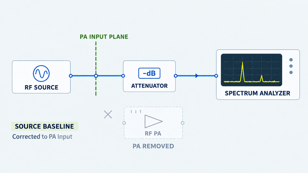
Remove the PA from the comparison path, or use an equivalent through connection that preserves a known measurement route, and measure the signal that would normally reach the PA input. Record the carrier and each suspicious spectral component at the same frequencies that will be checked after the PA is reinserted.
The source baseline answers whether the unwanted component was already present before the amplifier. If the same line is visible at the PA input reference plane, the final output spur cannot be described as purely created from nothing inside the PA. The amplifier may still amplify that component, change its relative level, mix it with other content, or add additional distortion, so the source-baseline result is not a clean bill of health for the PA.
If the source baseline is already unsuitable for the intended test, correct or characterize that condition before judging the amplifier. Depending on the setup, that may mean reviewing source output level, the SDR or driver state, path loss, filtering, or a substitute source. Measure the RF that actually reaches the PA input rather than relying only on software settings or a generator display.
For SDR-driven chains, the practical boundary is the physical RF presented to the PA. The existing SDR-before-PA verification method is the appropriate deeper route when the question becomes whether the upstream waveform, occupied bandwidth, drive, or unwanted spectral content is already wrong before amplification.
A source baseline should therefore leave you with a simple record: carrier frequency and level at the defined PA input reference plane, the frequency and level of each observed spur, the source settings, and the path used to obtain that measurement. If that baseline is not repeatable, do not proceed to a strong PA-origin conclusion.
3.Verify the Spectrum Analyzer Is Not Creating the Spur
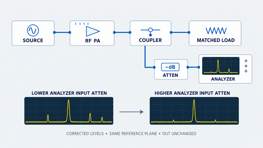
The spectrum analyzer is part of the measurement chain. A strong carrier can drive its front end, mixer, or internal stages into a region where the instrument generates harmonics or intermodulation products of its own. The displayed spur can then change even though the DUT output has not.
Keep the source, PA, load, and other DUT conditions unchanged while changing only the analyzer front-end loading within the instrument’s safe operating range. Increase analyzer input attenuation, or add appropriate external attenuation, so the analyzer sees less power. If external attenuation is added, include its documented correction before comparing levels at the same reference plane.
Compare the corrected spur level and the carrier-to-spur relationship before and after the receiver-loading change. A material change that tracks analyzer front-end drive while the DUT condition stays fixed supports a measurement-chain contribution and should be resolved before the PA is blamed. The observation shows that receiver operating point affects the result; it does not classify every visible line as instrument-generated.
Resolution bandwidth also affects what can be seen because it changes noise-floor and measurement-resolution behavior, but RBW by itself does not identify where a spur originated. The detailed RBW and harmonic-measurement setup boundary is the right place to review settings when two harmonic results are not traceable to equivalent analyzer conditions.
Do not continue a DUT fault judgment if the analyzer is overloaded, its safe input boundary is uncertain, or the displayed result changes with receiver loading in a way that has not been explained. Fix the measurement setup first.
4.Reinsert the PA and Compare the Same Spur Under Matched Conditions
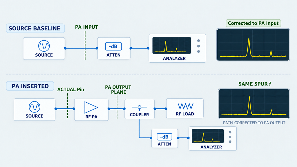
Once the source baseline and analyzer behavior are understood, reinsert the PA and reproduce the test using the same frequency, waveform, Actual Pin, load, relevant thermal state, and comparable analyzer setup. Track the same suspicious frequency rather than comparing two unrelated screenshots.
If the same spectral line is already present at the PA input and remains visible at the output, the source chain is at least one contributor. Compare how the carrier and the spur change through the amplifier, but avoid calling the output component “PA-generated” without qualification. The PA may be passing, amplifying, compressing, or interacting with an existing unwanted component.
If the input baseline does not show the line at a level the measurement can resolve, but the line appears repeatably after the PA is inserted, the evidence shifts toward the PA or a path that exists only in the PA-inserted setup. That is a stronger diagnostic result, but it still needs the analyzer check from the previous section and, where relevant, the physical-path checks later in this article.
Actual Pin controls whether this comparison is meaningful. Too much drive can push a PA toward compression and change its spectrum, while too little drive can create a test point that does not represent the intended operating condition. If the generator setting is being treated as the PA input without a defined input reference plane, align that condition using the RF PA input-power measurement method before interpreting the spur comparison.
Use the table as a decision aid; each row ranks evidence strength rather than assigning an absolute root cause.
| Observation | What it more strongly supports | What it does not prove | Next check |
|---|---|---|---|
| The same spur is present at the source baseline before the PA | Upstream source or driver contribution | That the PA has no influence on the output spur level or mechanism | Reinsert the PA under matched conditions and compare carrier and spur behavior |
| The spur remains visible through a PA-bypass or through connection | Source-chain or measurement-chain contribution | That the analyzer is linear or that the PA would not add separate distortion | Change analyzer front-end loading while keeping the source condition fixed |
| The displayed spur changes materially when analyzer input attenuation changes but DUT conditions do not | Analyzer or receiver contribution | That every spur in the measurement is instrument-generated | Re-establish a linear analyzer operating point and repeat the source/PA comparison |
| The spur is not resolved at the PA input but appears repeatably after the PA is inserted | PA or PA-inserted-path contribution | A confirmed internal PA defect | Verify analyzer linearity, repeatability, reference planes, and setup-dependent coupling |
| The spur grows disproportionately as the PA is driven toward a nonlinear operating region while source purity remains controlled | PA nonlinearity becomes more credible | A universal harmonic or intermodulation law, or a confirmed component-level root cause | Perform a limited drive comparison and check whether the source spectrum changes at the same time |
| The spur changes with cable routing, enclosure state, grounding, shielding, or control/DC configuration | Coupling, reference-path, shielding, or integration effects become more credible | That the PA active device is fault-free or that one specific coupling path is confirmed | Change one setup variable at a time and route to the relevant grounding or shielding diagnosis |
5.Use a Drive Sweep to Test Whether the Spur Behavior Changes
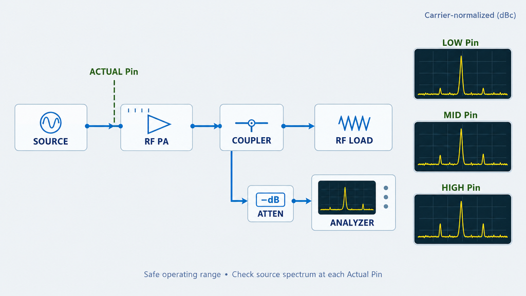
A limited drive sweep can add useful evidence because PA-generated nonlinear products often depend on operating point. The comparison should stay within the approved and safe input range for the device and should use only enough points to show whether the suspicious line behaves differently as the PA moves toward a more nonlinear state.
Record Actual Pin at the PA input reference plane at each point. Also record the carrier and suspicious spur, and note any accompanying change in gain, current, protection state, or other condition that would make the points non-comparable.
If the source spectrum remains controlled while a previously weak or absent output spur becomes much stronger as the PA is driven toward compression, that trend is consistent with increasing PA nonlinear contribution. It is not a universal proof rule. Different harmonics, intermodulation products, source impurities, feedback paths, and measurement limits can produce different slopes, so do not use a fixed “N dB spur change per 1 dB drive change” as a general diagnostic law.
The same caution applies to the source. A source or driver may itself become less clean as its output setting rises. If source purity changes at the same time as PA drive, the sweep no longer isolates the amplifier. In that case, measure the source baseline again at the corresponding input condition before drawing a PA conclusion.
Stop the sweep if the project input boundary is reached, protection activates, thermal state becomes uncontrolled, or the source and analyzer can no longer be held in comparable conditions. At that point, the existing data no longer isolate the cause.
6.Check the RF Path, Grounding, and Shielding When the Setup Changes the Result
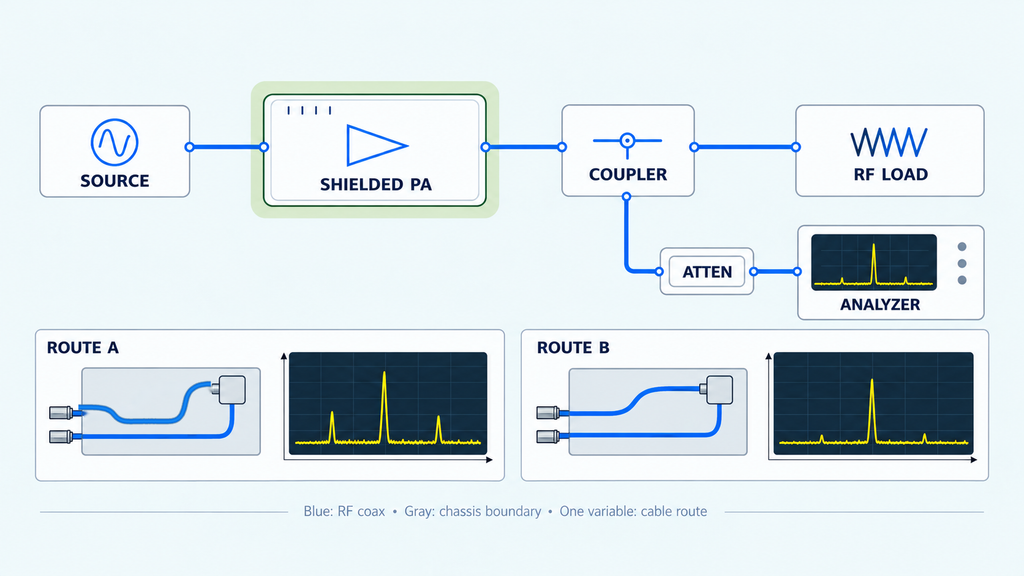
The setup itself can be a third contributor. A spur that changes when a cable moves, a lid is installed, a chassis bond changes, a control line is connected, or the grounding arrangement changes may be responding to coupling or reference-path conditions outside the PA active device.
Treat that behavior as a controlled-variable clue. Change one physical or electrical boundary at a time while keeping the RF source and PA operating point stable. Record the exact change and whether the spur response is repeatable. If several setup variables are changed together, the result is correlation without useful isolation.
A shielding-sensitive result may be associated with a seam, connector opening, cable entry, harness, or bonding boundary; the detailed RF PA shielding and EMI isolation process belongs in its specialist diagnosis rather than being reproduced here. Similarly, a result that follows the electrical reference or return path should be routed to the RF PA grounding and reference-path review.
If a spur follows setup changes, investigate the setup before declaring an internal PA defect. That behavior does not prove the PA is fault-free or identify a specific coupling path until the change can be isolated and reproduced.
7.Build a Spur Isolation Record for Engineering or Acceptance Review
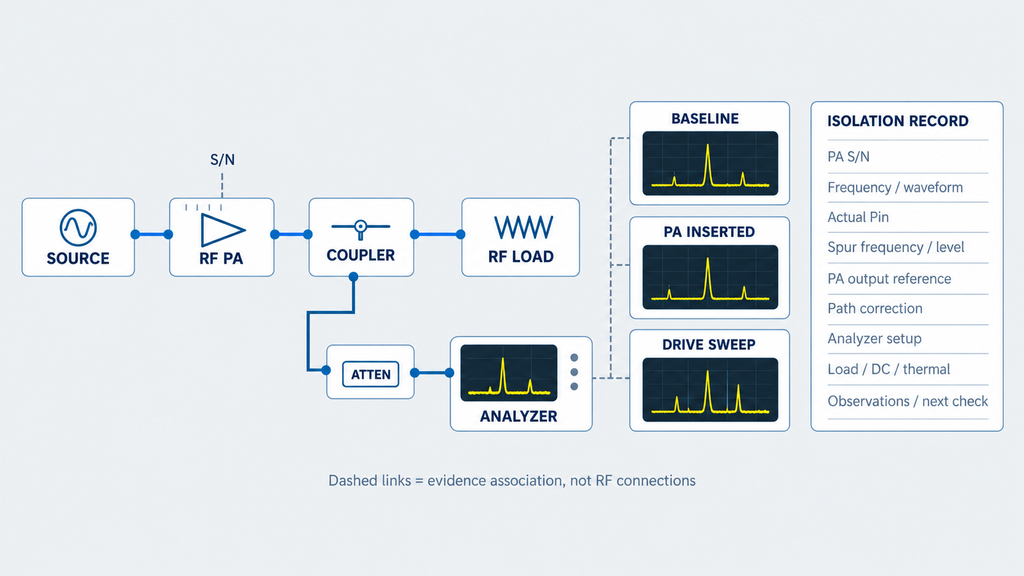
A useful troubleshooting result is a traceable record showing which conditions were held constant, which variable was changed, what happened to the suspicious line, and what alternatives remain.
For engineering review, record at least the following:
- Frequency and waveform: operating frequency, CW or modulation condition, and occupied bandwidth where relevant.
- Source condition: signal-generator, SDR, or driver identification and the actual settings used.
- Actual Pin: input power at the defined PA input reference plane, including the applicable source-path correction or calibration method.
- PA output reference plane: the exact point represented by the output result and whether the value is raw or corrected.
- Load condition: matched load, defined mismatch, or other approved RF load; include VSWR or reflection information only when it is actually part of the test.
- DC condition: Vdc and Idc at the relevant measurement points under the recorded operating state.
- Cooling and thermal state: mounting/cooling condition and whether the result is cold, transitioning, or at a project-defined stabilized condition.
- Analyzer setup: instrument identification, reference level, input attenuation, RBW, VBW where used, and any preamplifier or other front-end state that affects dynamic range.
- External RF path: attenuators, couplers, filters, cables, adapters, and the correction terms applied to the relevant path.
- Spur record: suspicious frequency, measured level at the stated plane, and the measurement status needed to interpret it.
- Source or through result: whether the same line was present with the PA removed or bypassed.
- PA-inserted result: whether and how the same line changed after the PA was restored under matched conditions.
- Drive-comparison points: Actual Pin and corresponding carrier/spur observations at each safe test point.
- Conclusion strength: what the evidence supports, what it does not prove, and the next verification action.
If any of the comparison-critical fields are missing, mark the diagnosis as needing retest or further evidence rather than forcing a final root cause.
For supplier or shipment review, tie the isolation record to the unit and configuration scope required by the project. A result from one unit should not be generalized to a batch or product series without the corresponding evidence.
RF SKYPOWER can review a documented spur-isolation package in the context of an RF PA engineering discussion, but the package should contain the conditions above rather than only an output screenshot. That review can identify what should be tested or compared next; it should not be described as a guaranteed root-cause determination without the necessary project evidence.
Conclusion: Prove the Spur Origin Before You Change the PA
Do not replace or reject an RF PA only because a non-expected spectral line appears at its output. Establish the source baseline and a valid analyzer operating point, then compare the same spur across the defined PA input and output reference planes under controlled operating conditions. A line present before the PA supports upstream contribution; a line that appears repeatably only after PA insertion, while the source and analyzer remain controlled, is stronger evidence of PA involvement but is not by itself proof of an internal defect.
Use the isolation record to choose the next action: correct or characterize the source chain when the spur is already present upstream; restore the measurement setup when the result follows analyzer loading; isolate grounding, shielding, or path coupling when the setup controls the result; and continue PA-level investigation when the spur remains tied to the amplifier under comparable conditions. Product-specific limits, acceptance thresholds, and a final component-level root cause still require the applicable project evidence.
For RF SKYPOWER engineering review, send the operating frequency and waveform, source baseline, PA model/S/N/configuration, Actual Pin and reference planes, suspicious spur frequency and level, analyzer settings, load/DC/thermal condition, and the through, PA-inserted, and drive-comparison results. The RF power amplifier module range is a product-family route for further evaluation; project suitability still requires engineering review.