








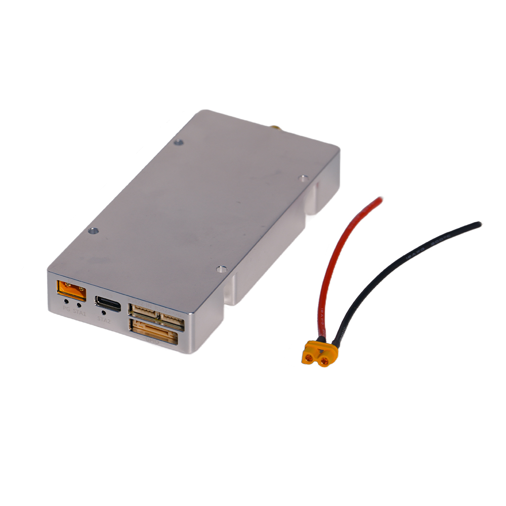
CUSTOM IQ / SCALABLE INTEGRATION
HZS1006000-F1
100 MHz–6 GHz SDR architecture supporting custom-IQ workflows and up to 200 MHz real-time bandwidth. Validation should remain tied to the actual physical RF output and approved playback configuration.


High-performance systems engineered for consistent, dependable operation under critical conditions.
See It in Action
High-performance systems engineered for consistent, dependable operation under critical conditions.
See It in Action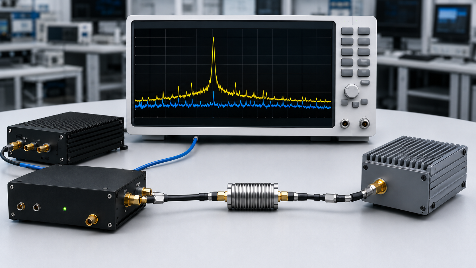
Drone jammer testing can fail before the power amplifier is even connected. An SDR interface may show the expected frequency and an enabled RF output while the physical signal at the RF connector still differs from what the PA is supposed to receive.
That matters because the PA responds to the RF waveform and power that actually reach its input reference plane—not to the SDR software setting. A configuration error, unexpected occupied bandwidth, insufficient drive margin, or unwanted spectral component can therefore become an integration problem once amplification begins.
The first decision is not whether the PA can produce high power. It is whether the SDR output has produced enough measured evidence to enter the amplified RF chain.
What should be verified at the SDR output and PA input boundary before that connection is approved?
These checks should begin with low-power conducted measurements in a controlled 50-ohm test environment. They should not involve uncontrolled live-air transmission toward real aircraft or field testing outside the applicable authorization.
This guide compares two SDR architectures documented in current RF SKYPOWER product information:
Both SDRs cover 100 MHz–6 GHz, but their bandwidth and RF-output architectures create different evidence requirements before PA integration.
CUSTOM IQ / SCALABLE INTEGRATION
100 MHz–6 GHz SDR architecture supporting custom-IQ workflows and up to 200 MHz real-time bandwidth. Validation should remain tied to the actual physical RF output and approved playback configuration.
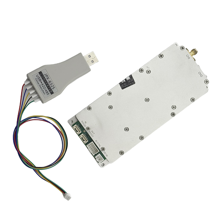
DUAL RF OUTPUT ARCHITECTURE
100 MHz–6 GHz SDR architecture with two independent RF outputs and 100 MHz bandwidth per channel. Each physical output should first be validated independently before simultaneous operation is evaluated.
| Validation Difference | HZS1006000-F1 | HZSDR1006000-A01 |
|---|---|---|
| Frequency Coverage | 100 MHz–6 GHz | 100 MHz–6 GHz |
| Bandwidth Architecture | Up to 200 MHz real-time bandwidth | 100 MHz bandwidth per channel |
| RF Output Validation | Follow the physical RF output used in the approved configuration | Validate Output 1 and Output 2 independently |
| Key Evidence Before PA | IQ identity, playback configuration, occupied bandwidth, and measured RF output | Per-output configuration, measured RF output, and simultaneous-output condition |
The same Pre-PA Validation Gate applies to both. The required evidence changes with waveform, bandwidth, RF-output topology, control method, expansion plan, source-path losses, and operating environment.
For broader RF-chain context, see how drone signal jamming works.
The SDR generates the RF waveform. The PA increases its power.
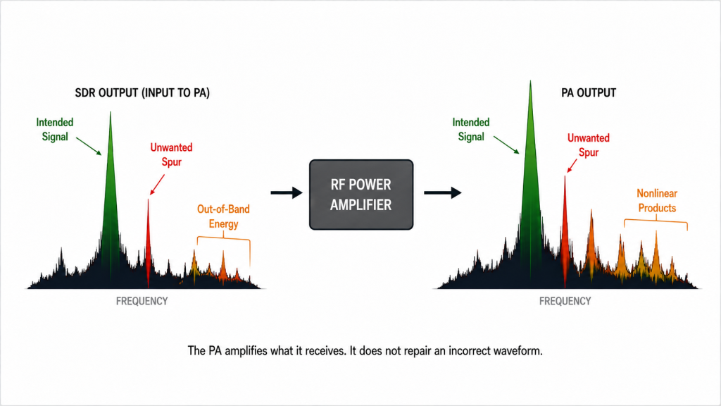
If the SDR output contains an incorrect center frequency, excessive occupied bandwidth, an unwanted spur, or clipped peaks, the PA cannot be expected to restore the intended signal. Depending on its operating condition, the PA may also introduce:
This creates an important integration rule:
A separately tested SDR and a separately tested PA do not automatically form a validated RF chain.
The combined system must still be checked for:
This remains true even when two SDR architectures share the same headline tuning range.
The F1 and A01 both cover 100 MHz–6 GHz, but their integration records are not identical. One may rely on a custom-IQ and scalable multi-unit workflow, while the other uses two independent physical RF outputs. Frequency coverage alone cannot define the required test procedure.
A formal Pre-PA Validation Gate provides a controlled decision point before an unverified SDR configuration is connected to the amplified RF chain.
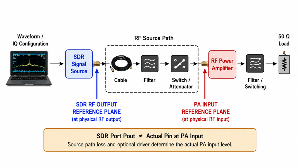
A simplified conducted RF chain is:
IQ or waveform configuration
→ SDR signal source
→ Driver or power amplifier
→ Filter and RF switching
→ 50-ohm load or authorized test boundary
Each stage has a different responsibility, and each measurement should be tied to a defined reference plane.
IQ data describes how signal amplitude and phase change over time.
A waveform configuration may define:
A successful upload or correct filename does not prove that the physical RF output is correct.
For an F1 configuration using a custom IQ file, the validation record should identify:
Changing one of these values creates a new waveform condition that may require revalidation.
For an A01 configuration, preserve the selected waveform or signal setting, host-software and firmware versions, channel assignment, and the measurement associated with each physical RF output.
The SDR converts the digital configuration into a low-power RF waveform.
Validation must therefore take place at the physical RF output, not only in software. Engineers should confirm:
The A01 provides two independent RF outputs. Each output should be measured independently before simultaneous operation is evaluated.
The F1 uses a dual-PHY processing architecture. This should not automatically be interpreted as a specific number of independent physical RF output connectors. The test plan must follow the physical output topology used in the approved configuration.
The RF level reaching the PA input may differ from the measured SDR-port output because the source path can include:
The SDR-to-PA boundary must therefore distinguish between:
The SDR-port value should not be treated as the PA input level unless the intervening path has been defined and corrected.
The first validation stage should remain on the low-power side of the system.
A basic conducted setup may use:
SDR signal source
→ calibrated attenuation
→ spectrum analyzer or vector signal analyzer
Depending on instrument limits and SDR output, the setup may also include:
The test boundary should be:
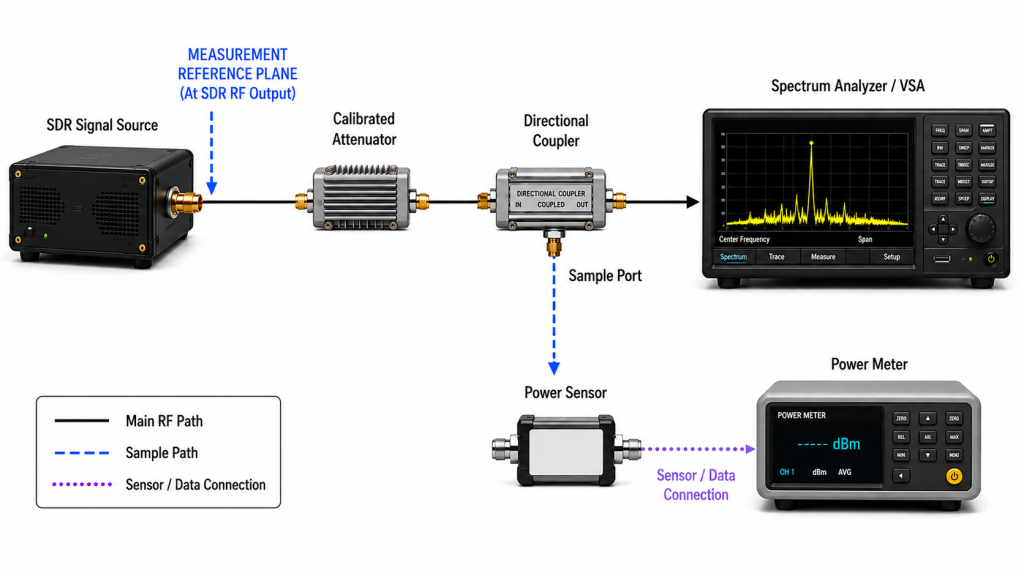
A measurement has limited value if the report does not state where it was taken.
The record should identify:
For an A01 dual-output configuration, the test may require two calibrated measurement paths or a controlled procedure for moving the same equipment between outputs.
For an F1 configuration, identify the actual physical RF output used rather than inferring the reference plane from the internal processing architecture.
| Check | What to Measure | Failure Indication | Why It Matters Before the PA |
|---|---|---|---|
| Center frequency | Set frequency vs. measured frequency | Frequency offset | PA and downstream filters may not align |
| Bandwidth | Configured vs. occupied bandwidth | Signal too wide or too narrow | Unwanted spectrum may enter the amplified path |
| Drive level | Actual RF level at the PA input plane | Outside the defined PA input window | Underdrive or PA overdrive/compression risk after connection |
| Output flatness | Level across the used bandwidth | Band-edge loss or ripple | Downstream gain variation may increase the error |
| Spectral quality | Spurs and out-of-band energy | Unexpected components | Unwanted energy may be carried forward or amplified |
| Peak behavior | PAPR and clipping | Flattened waveform peaks | Increased distortion and reduced headroom |
| Repeatability | Restart and long-duration results | Inconsistent output | Integration result may not be reproducible |
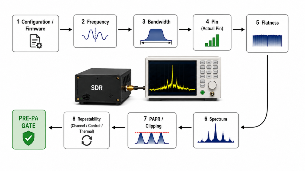
A test result is useful only when the condition that produced it can be reproduced.
Record:
Also confirm behavior after:
A spectrum screenshot without its configuration record cannot establish which settings produced the result.
For F1 custom-IQ operation, each measurement should be tied to the exact file and playback configuration. For A01, independent outputs should retain their own configuration and measurement records.
The configured center frequency is where the software instructs the SDR to place the signal.
The measured center frequency is where the RF energy actually appears.
The report should include both.
Possible contributors to offset may include:
For CW, frequency can be measured directly.
For wideband, swept, or frequency-hopping waveforms, define whether the recorded value represents:
One center-frequency screenshot cannot validate an entire swept or frequency-hopping waveform.
The F1 and A01 both cover 100 MHz–6 GHz, but a result at one frequency does not establish behavior across the full range. Validation should cover the operating points required by the actual RF chain.
For A01, repeat the frequency check on each physical output.
Three bandwidth terms should remain separate.
Configured bandwidth is the software setting.
Real-time or instantaneous bandwidth describes what the hardware architecture can generate at the same time.
Occupied bandwidth is the frequency range actually containing the waveform energy under the defined measurement method.
An architecture supporting up to 200 MHz does not mean every waveform occupies 200 MHz.
For F1, measure the occupied bandwidth of the actual loaded waveform rather than copying the maximum architecture value into the test result.
For A01, define the validation result for each physical output and state whether it applies to:
Measured occupied bandwidth should also be reviewed against:
The PA input requirement depends on more than the SDR’s nominal output setting.
Relevant factors include:
When RF power is expressed in dBm and path gain or loss in dB:
**Actual Pin at the PA input (dBm)
≈ measured SDR-port output (dBm)
− source-path loss (dB)
Source-path loss may include cable, connector, filter, switch, and attenuator losses.
This first-order estimate defines the RF level reaching the PA input reference plane. It does not prove final PA output performance.
Final compatibility must be confirmed from measured input-to-output behavior at the required frequency, waveform, operating level, load condition, and relevant thermal state.
The SDR should also retain enough adjustment range for frequency-dependent gain, calibration, unit variation, path loss, waveform back-off, and integration changes.
DC supply compatibility and RF drive compatibility remain separate questions.
A wideband waveform should not be approved from one center-frequency reading.
Measure output across the occupied bandwidth relevant to the application.
Possible failures include:
SDR-only flatness and combined SDR-plus-PA flatness should remain separate results.
For A01, measure Output 1 and Output 2 independently before the intended simultaneous condition.
For F1, evaluate flatness through the physical RF path used in the final assembly.
A spur is an unwanted frequency component separate from the intended signal. Out-of-band energy exists outside the intended occupied spectrum.
Possible contributors include:
The record should define:
After low-power SDR validation, repeat spectral measurements with the PA and relevant downstream RF path under the required operating condition.When the PA stage is added, use a defined swept-frequency full-power RF PA test to verify the amplified path under controlled operating conditions.
Unwanted components within the amplified path may be carried forward or amplified, while nonlinear PA operation may introduce additional spectral products.
A waveform change should trigger a new spectral-quality check.
Peak-to-average power ratio, or PAPR, describes the difference between a waveform’s highest instantaneous power and its average power.
CW has relatively stable amplitude. OFDM and many custom IQ waveforms can contain short peaks well above the average level.
Two waveforms with the same average RF output can therefore create different requirements for:
Clipping occurs when waveform peaks exceed the available hardware range.
Depending on the waveform and system, clipping may contribute to:
A CW result and an OFDM result should therefore not be treated as equivalent output conditions.
The important question is whether the tested waveform remains within the required linearity, spectral, and PA-drive boundary.
EVM should not be used as a universal acceptance metric. It is most meaningful when the test reproduces a defined modulation or communication standard with an appropriate reference.
A multi-channel or multi-module SDR requires more than one acceptable spectrum screenshot.
The validation plan may need to include:
For A01, record relevant results for:
For cascaded F1 configurations, preserve:
Current product documentation describes RS422 cascading of up to 10 F1 units. A successful single-unit result therefore does not establish the RF behavior of the final cascaded configuration.
The A01 supports multi-module addressing and control; the maximum supported module quantity should be confirmed for the approved product revision before RFQ.
The documented operating ranges are:
A room-temperature result does not establish performance across an extended-temperature deployment requirement. Where temperature range matters, repeat the required RF, control, restart, and stability checks at defined test conditions.
Different waveform families create different RF measurement priorities.
| Waveform | Primary Test Priority | Do Not Rely On |
|---|---|---|
| CW | Frequency accuracy and RF output level | CW alone to predict wideband behavior |
| OFDM | Occupied bandwidth, PAPR, clipping, and spectral regrowth | Average power alone |
| LFM | Sweep range, timing, and flatness | One center-frequency measurement |
| Custom IQ | File integrity, playback behavior, and occupied spectrum | Filename or software setting alone |
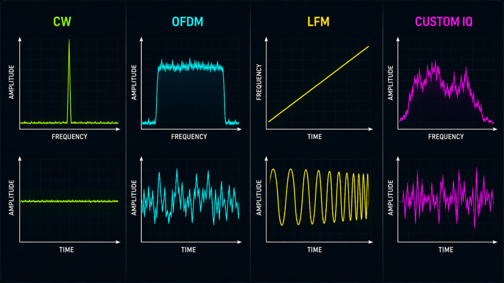
CW is useful for checking basic frequency accuracy, RF output level, cable loss, gain, compression behavior, and thermal behavior at a stable carrier.
It does not represent the peak behavior of OFDM or the bandwidth behavior of a custom IQ waveform.
OFDM testing may require:
Acceptance limits must be tied to the actual waveform and downstream PA boundary.
For LFM, check:
A single center-frequency measurement cannot validate the complete waveform.
Record:
For an F1 custom-IQ workflow, successful file loading is only the beginning of validation. Acceptance must come from measured RF output under the recorded configuration.
The Pre-PA Validation Gate does not replace a full PA gain and compression evaluation. It only determines whether the SDR-side RF boundary is sufficiently defined before amplification.
It should answer three questions.
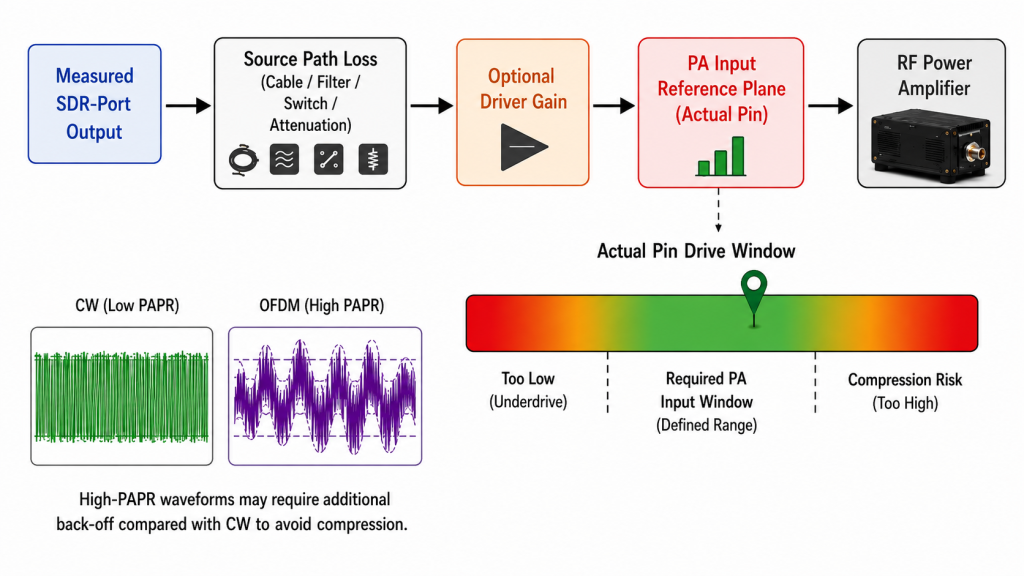
Determine the RF level at the PA input reference plane after accounting for path loss and any defined driver-stage gain.
Insufficient Actual Pin may prevent the PA from reaching the required operating point.
SDR-port output and PA-input power are not interchangeable when RF components exist between them.
Normal operation should not depend on keeping the SDR at one extreme of its output range unless that condition has been deliberately validated.
Margin may be required for:
The useful question is whether the SDR can reach and control the required PA input level across the defined operating conditions.
A high-PAPR waveform may require a lower average PA input than CW.
The required back-off depends on:
A dual-output A01 feeding separate PA paths requires the drive boundary to be established for each path. A multi-unit F1 configuration may require the same verification for each physical path in the final assembly.
Detailed PA gain matching should remain a separate calculation using measured PA behavior at the required frequency, waveform, thermal condition, and output target. For the detailed method, see matching SDR drive to PA gain.
F1 and A01 should not be compared only by their shared 100 MHz–6 GHz tuning range.
Their architectures change what evidence must be preserved during validation.
| Architecture Characteristic | Validation Evidence to Preserve |
|---|---|
| F1 custom-IQ workflow | IQ file identity, version or checksum, sample settings, playback configuration, and measured RF output |
| F1 architecture supporting up to 200 MHz real-time bandwidth | Configured bandwidth, actual occupied bandwidth, waveform condition, and analyzer settings |
| F1 cascading | Module identity, addressing, command order, start-up sequence, physical RF path, and corresponding measurement result |
| A01 dual independent RF outputs | Output 1 result, Output 2 result, channel configuration, and intended simultaneous-output condition |
| A01 100 MHz-per-channel architecture | Per-channel configured and occupied bandwidth with the physical output identified |
| A01 multi-module control | Module addressing, channel assignment, command execution, restart repeatability, and approved expansion boundary |
| A01 extended operating-temperature range | Test temperature and associated RF/control results |
| Different SDR supply-voltage boundaries | Recorded DC configuration, while keeping DC compatibility separate from RF drive compatibility |
The table does not prove that one SDR architecture is universally better than another. It shows why the validation record must follow the physical architecture and actual project condition.
Product-specific limits and interface capabilities should be checked against the approved datasheet, firmware, and product revision used for the project.For current hardware options, review the SDR signal source modules before freezing the source architecture.
Before quotation or integration review, define:
For shipment-level release evidence beyond the SDR-to-PA gate, use the C-UAS RF PA acceptance checklist to define the required evidence scope and release boundary.
Send RF SKYPOWER your required frequency range, waveform family, occupied or instantaneous bandwidth, channel count, target PA model, required Actual Pin at the PA input reference plane, source-path loss, duty cycle, control interface, supply voltage, cooling condition, operating temperature, and required test evidence. We can review the SDR-to-PA integration boundary before quotation.
Only after the SDR output and PA input boundary have been shown to be compatible under the intended operating condition.
The review should include frequency coverage, Actual Pin at the PA input reference plane, impedance and connector compatibility, waveform requirements, source-path loss, and available drive margin.
Low-power conducted validation should be completed before the amplified RF chain is approved.
Yes. Each physical output should first be measured with its own reference plane and configuration identified.
If both outputs operate simultaneously in the final system, that condition should then be checked for relevant changes in RF level, occupied spectrum, isolation, control behavior, supply loading, and thermal repeatability.
Drone jammer testing should approve the SDR-to-PA boundary only after the physical SDR output has been measured under the waveform, frequency, bandwidth, channel, and RF-path conditions that the PA will actually receive. An enabled RF-output setting in software is not sufficient evidence.
A PA should not be expected to repair an unverified SDR waveform. Unwanted components within the amplified path may be carried forward or amplified, while nonlinear PA operation may introduce additional distortion and spectral products.
The acceptance decision therefore depends on a defined measurement reference plane, measured Actual Pin, occupied bandwidth, spectral quality, waveform peak behavior, channel state, and repeatability—not on a software status indicator or one isolated RF screenshot.
For an SDR-to-PA engineering review, provide RF SKYPOWER with the required frequency range, waveform family, occupied or instantaneous bandwidth, channel count, target PA, PA-input requirement and reference plane, source-path loss, duty cycle, control interface, supply voltage, cooling condition, operating temperature, and required test evidence.