








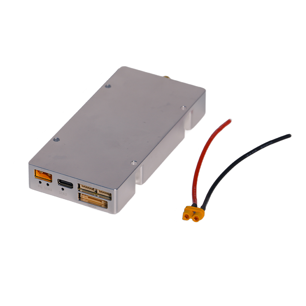
CUSTOM IQ / CASCADING ROUTE
A stronger starting point when the system needs custom IQ loading, up to 200 MHz real-time bandwidth, RS422 AT-command control, and documented multi-unit cascading.


High-performance systems engineered for consistent, dependable operation under critical conditions.
See It in Action
High-performance systems engineered for consistent, dependable operation under critical conditions.
See It in Action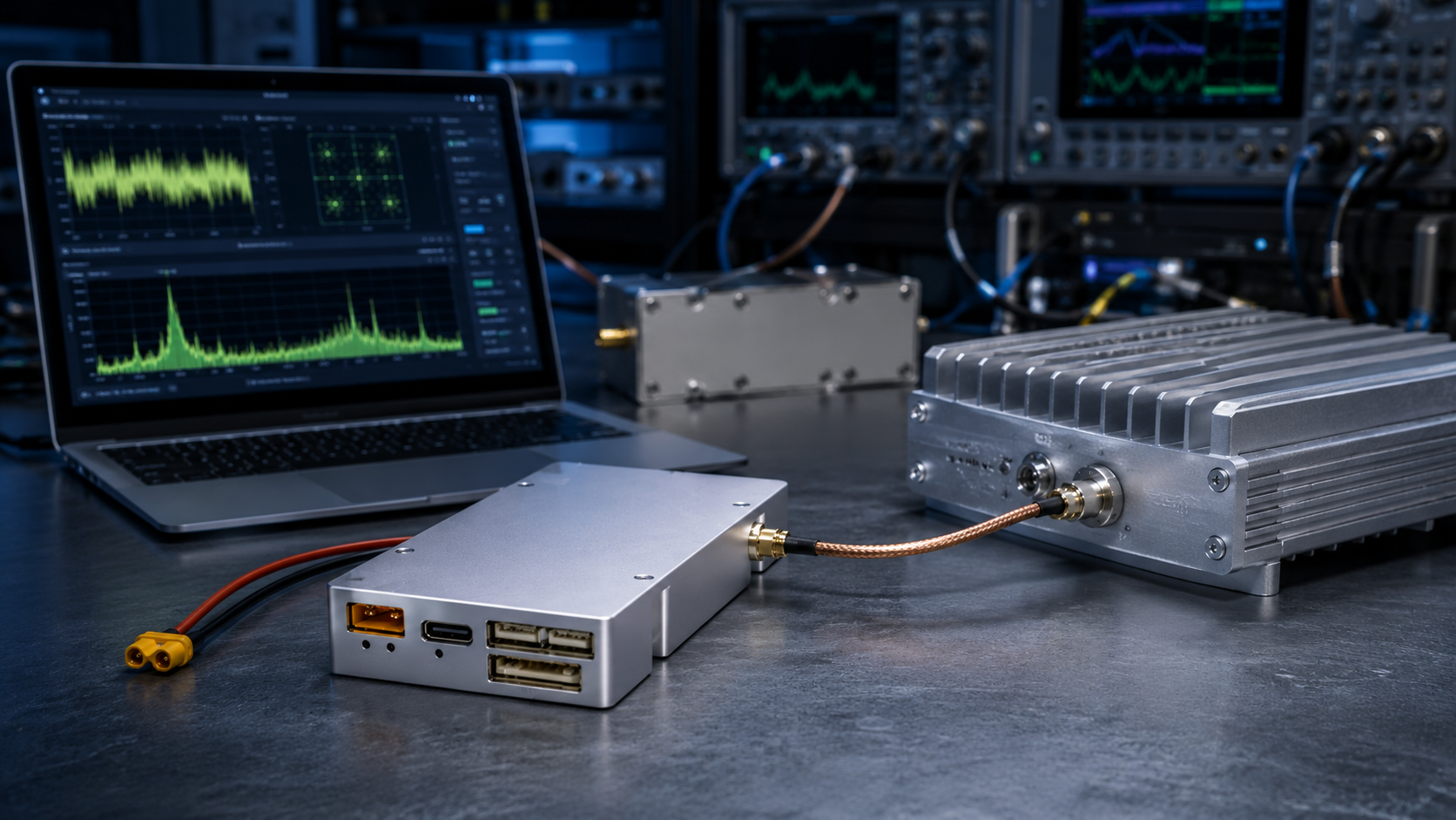
Drone signal jamming is often reduced to finding a drone’s frequency and adding more RF power. That can create false confidence before hardware selection because command, telemetry, video, navigation, and autonomous behavior do not represent one interchangeable link.
In an authorized C-UAS RF chain, an SDR source can provide the configurable waveform and RF drive needed by the downstream power stage, but tuning range or maximum source output alone does not show whether the complete chain will work as intended.
Before selecting the SDR source, what must the integrator verify about the authorized link, waveform boundary, physical RF paths, PA drive interface, and final RF chain?
A drone does not necessarily depend on one wireless connection.
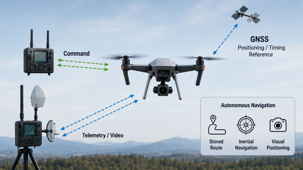
Depending on the platform, it may use:
These functions should not be treated as interchangeable.
The command link carries flight instructions from the operator or control system. The video link returns camera imagery.
If the video link becomes unavailable, the operator may lose the live image while the aircraft remains controllable. If the command link is interrupted, the flight controller may enter a predefined fail-safe state.
Possible responses include:
The actual response depends on the aircraft model, firmware, configuration, and available alternative links. Interrupting one link does not guarantee one universal result.
GNSS provides positioning and timing information. It does not normally carry flight commands from the operator.
If reliable GNSS information becomes unavailable, the aircraft may still use:
GNSS interruption and control-link interruption are therefore different engineering problems.
A detector attempts to discover, identify, or track a drone or its signal.
In this RF chain, the SDR signal source generates or loads the configurable waveform and supplies the RF drive signal required by the downstream power-amplifier stage.
These stages may work together, but none should be treated as a complete Counter-UAS system on its own.
The first engineering question should be:
Which link is within the authorized system scope, and what evidence shows that it has been correctly identified?
For the module-level relationship between the signal source, RF PA, internal RF path, control interfaces, and complete C-UAS system, review how a drone jammer module fits the C-UAS RF chain
A center frequency identifies only one part of a communication system.
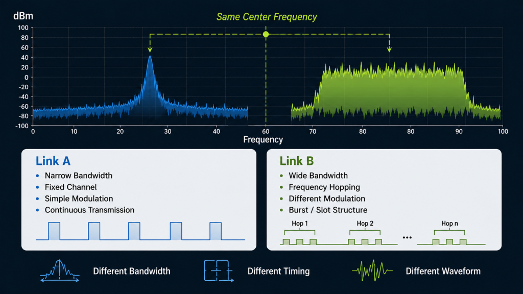
Two links operating in the same frequency region may still differ in:
This is why selecting an SDR source or RF power amplifier from a frequency list alone can lead to an incomplete system design.
Frequency coverage identifies where a source can be tuned.
A 100 MHz–6 GHz tuning range defines where the source can operate; it does not by itself mean that the entire span is generated simultaneously. Simultaneous spectrum is constrained by the source’s instantaneous bandwidth and physical RF-output architecture.
Instantaneous bandwidth describes how much continuous spectrum the source can generate at one time.
A wide tuning range may still be paired with a limited instantaneous bandwidth. A source may also provide a broad waveform around one selected center frequency without producing its full tuning range at once.
Frequency coverage does not define how the signal is generated.
The system may depend on:
Frequency coverage starts the review. It does not complete it.
An SDR source occupies the waveform-generation stage between the system controller and the RF power amplifier.
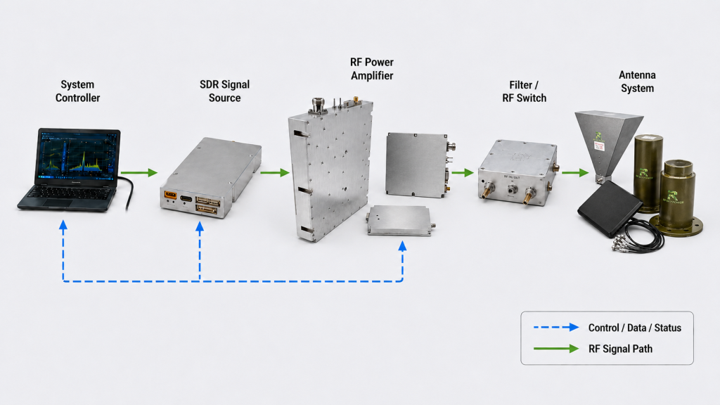
System Controller
        ↓
SDR Signal Source
        ↓
RF Power Amplifier
        ↓
Filter / RF Switch
        ↓
Antenna System
Each stage has a separate responsibility.
The controller manages operating logic. It may:
It does not normally create the final amplified RF output.
The SDR source generates or loads a digital waveform and converts it into a low-power RF signal.
Depending on the architecture, it may control:
This low-power output becomes the drive signal for the next RF stage.
The PA raises the source signal to the required output level.
Too little source drive may prevent the PA from reaching its target output. Excessive drive may push it toward compression, additional heat, and less predictable waveform behavior.
The source and PA should therefore be reviewed together:
A detailed explanation is available in how RF power amplifier gain should match SDR drive.
Filters help control unwanted output outside the intended RF path. RF switches route the signal to the required PA or antenna channel.
The antenna then determines how the conducted RF energy is distributed.
A configurable SDR source cannot compensate for:
The final result belongs to the complete RF chain, not to one module.
Bandwidth and IQ support are often grouped together under the term “SDR,” but they describe different capabilities.
A published 200 MHz value can represent different output arrangements.
HZS1006000-F1 supports up to 200 MHz of real-time bandwidth. HZSDR1006000-A01 provides up to 100 MHz per channel and 200 MHz across two channels.
The headline figure is similar, but the RF architecture is different.
One arrangement supports a wider source path. The other supports two independently controlled RF paths.
This distinction matters when the downstream design requires:
Combined bandwidth should not be interpreted as the maximum bandwidth available from every individual output.
IQ data uses two digital components to describe waveform amplitude and phase over time.
Custom IQ support allows an integrator to prepare a waveform file, load it into the source, and reproduce it under controlled conditions.
This can support:
HZS1006000-F1 supports USB loading of 16-bit complex IQ data. This allows the waveform library to be managed separately from the RF source hardware and selected through the control system.
The engineering value is not simply that the hardware is software-defined. The value comes from how the waveform is prepared, loaded, selected, controlled, and verified.
Internal processing resources do not automatically define the number of physical RF connectors.
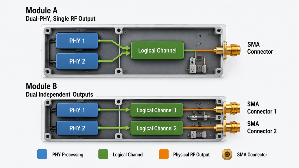
A PHY is an internal radio-processing path.
A channel may refer to a logical or configurable signal path.
An RF output is the physical connector that delivers the signal to the next stage.
These terms are related, but they are not interchangeable.
HZS1006000-F1 uses dual-PHY processing with one SMA RF output. HZSDR1006000-A01 provides two independent SMA outputs with separate channel settings.
This difference shows why internal channel terminology cannot replace a physical-interface review.
Before selecting a source, define:
Two physical outputs may simplify systems that require two PA chains, filter networks, or antenna paths.
However, two connectors do not automatically provide twice the range or twice the protected area. Each path still requires its own:
The correct question is not only:
How many channels does the SDR have?
It is:
How many independently usable physical RF paths does the complete system require?
Published SDR output values cannot be compared directly when they use different waveforms, bandwidths, or measurement conditions.
One source may be measured with a continuous-wave signal, while another may be tested with a wideband modulated waveform.
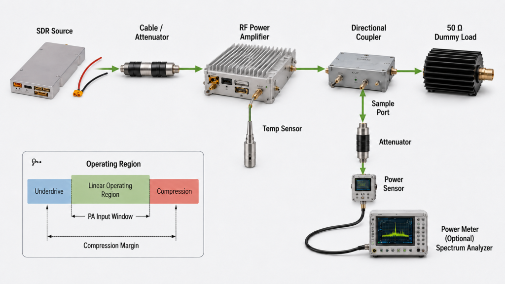
These conditions can produce different:
A higher CW reading does not automatically mean more usable drive under a wideband waveform.
The source-to-PA review should specify:
A PA may require a defined input level to reach its target output.
If the SDR produces less average power under the actual waveform than under the published test condition, the PA may not reach the expected result.
The opposite problem is also possible. A source setting that is acceptable at one frequency may overdrive the PA at another because PA gain and source output can vary across the operating range.
The review should therefore not stop at:
Test evidence should show:
Once the source boundary is defined, suitable RF Power Amplifier Modules can be evaluated against the required drive level and bandwidth.
The source should be selected from the complete integration boundary rather than one headline specification.
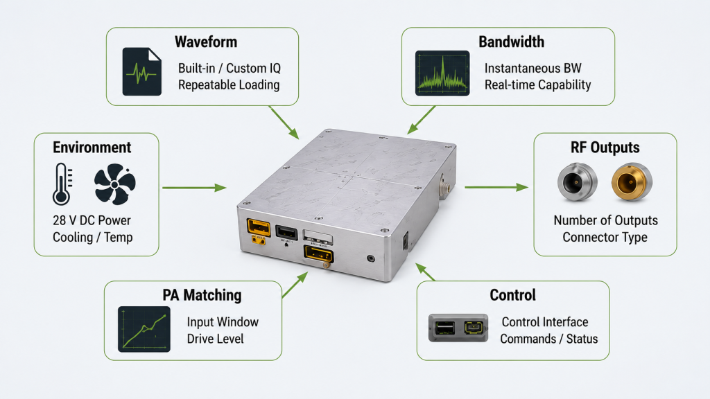
The two source architectures can then be compared by their confirmed design boundaries.
The following values are model-specific integration boundaries, not universal SDR specifications; confirm the approved hardware, firmware, interface, and datasheet revision before RFQ approval.
CUSTOM IQ / CASCADING ROUTE
A stronger starting point when the system needs custom IQ loading, up to 200 MHz real-time bandwidth, RS422 AT-command control, and documented multi-unit cascading.
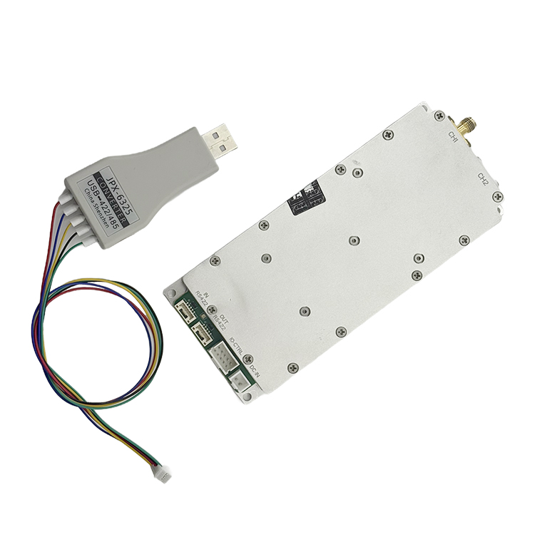
DUAL RF OUTPUT / WIDE TEMPERATURE ROUTE
A stronger starting point when two independent SMA outputs, up to 100 MHz per channel, a 9-32 V supply range, and wider operating temperature coverage are priorities.
| Selection Condition | HZS1006000-F1 | HZSDR1006000-A01 |
|---|---|---|
| Frequency Coverage | 100 MHz–6 GHz | 100 MHz–6 GHz |
| Real-Time Bandwidth | Up to 200 MHz | Up to 100 MHz per channel; 200 MHz combined |
| RF Output Architecture | Dual-PHY internal architecture with one documented external SMA output; confirm PHY-to-port routing. | Two independent SMA RF outputs |
| Custom IQ Support | USB upload of 16-bit complex IQ files; confirm the current .sc16 / .cs16 naming convention. |
Not documented in the current manual; confirm by RFQ. |
| Expansion | RS422 cascading of up to 10 units | Multi-module addressing and control supported; maximum quantity confirm by RFQ. |
| Control | RS422 AT-command control; customer application development supported | RS422 host control; custom API availability confirm by RFQ. |
| Supply | 28-32 V DC | 9-32 V DC |
| Operating Temperature | 0°C to 50°C | −40°C to +70°C |
Before RFQ: Confirm final firmware, physical RF-port routing, IQ-file convention, control/API availability, expansion limits, and the approved product revision.
A request that only specifies a 100 MHz–6 GHz SDR source does not provide enough information for engineering review.
A useful RFQ should include:
Use and testing should remain within the applicable authorization, deployment region, and approved RF test boundary.
RF SKYPOWER can review the waveform, bandwidth, output-path, PA, control, environmental, and acceptance requirements to identify the appropriate SDR and RF power architecture.
Discuss your SDR and PA integration requirements.
No. An SDR source creates a low-power RF signal. A complete authorized system may also require detection, system control, RF power amplifiers, filters, switches, antennas, power distribution, cooling, and test evidence.
No. Tuning range shows where the source can operate. Instantaneous bandwidth shows how much continuous spectrum can be generated at one time.
No. Dual-PHY describes internal processing resources. The number of physical RF outputs must be defined separately.
Not directly. CW and modulated waveforms may have different average power, peak-to-average ratios, measurement bandwidths, and PA drive requirements.
Define the waveform, bandwidth, source output, interstage loss, PA input window, PA gain, target output, compression margin, frequency points, and thermal condition.
Drone signal jamming depends on the target link, waveform, bandwidth, RF chain, and expected aircraft behavior—not only on tuning range or maximum power.
Real SDR architectures show why similar frequency and bandwidth figures can represent different engineering boundaries. One design may prioritize custom IQ, a wider source path, and controlled cascading, while another prioritizes two independent physical outputs and wider environmental limits.
Final selection should follow the waveform workflow, physical RF paths, PA input requirement, control interface, operating environment, expansion plan, authorization boundary, and acceptance evidence.
Contact RF SKYPOWER with the authorized application, required tuning range, instantaneous bandwidth, waveform or IQ workflow, number of physical RF outputs, PA input window, target RF-chain boundary, control interface, operating environment, module quantity, and acceptance-evidence requirements. We can then review the appropriate SDR source and RF power architecture for the approved project scope.