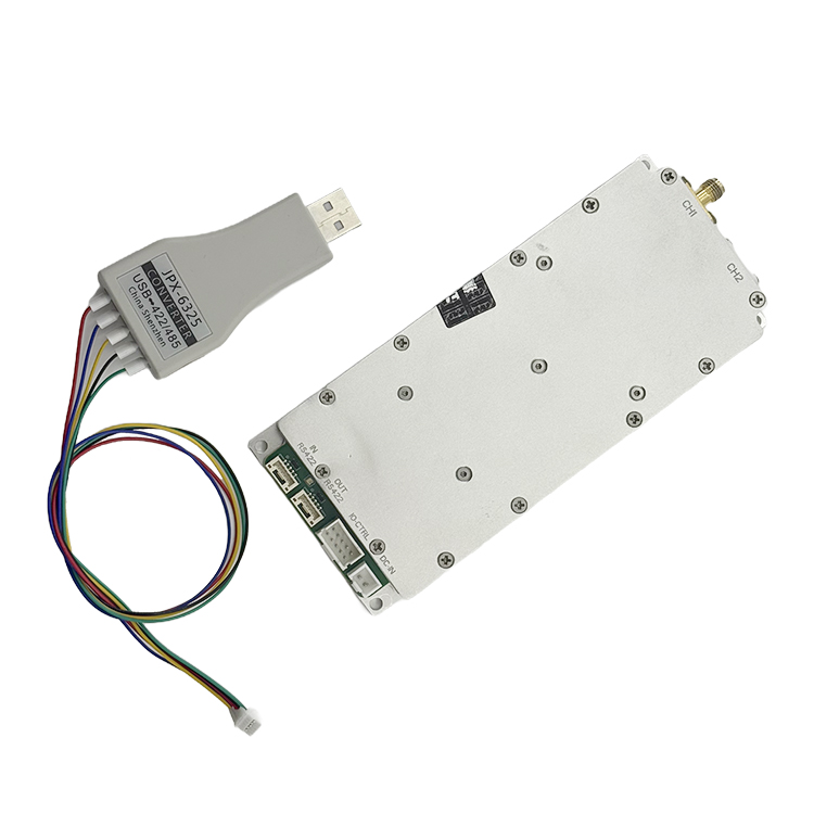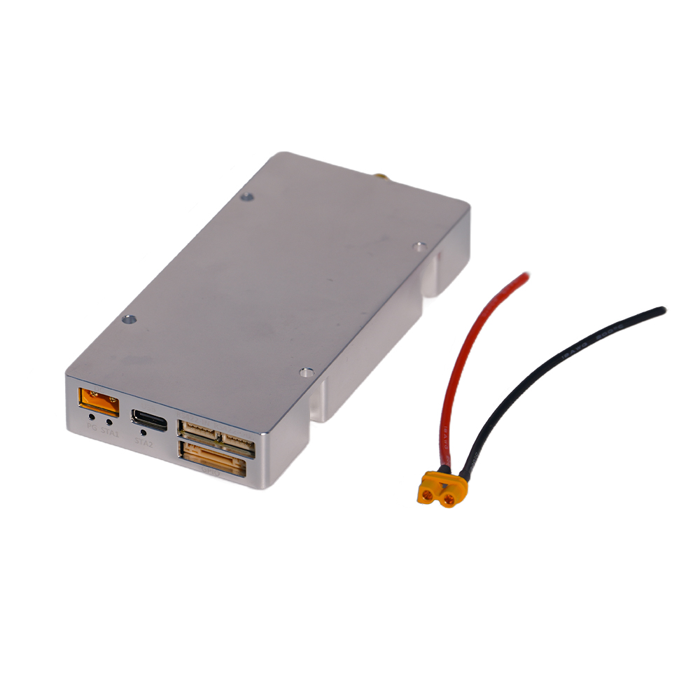
CUSTOM IQ / CASCADING ROUTE
A stronger starting point when the system needs custom IQ loading, up to 200 MHz real-time bandwidth, RS422 AT-command control, and documented multi-unit cascading.


High-performance systems engineered for consistent, dependable operation under critical conditions.
See It in Action
High-performance systems engineered for consistent, dependable operation under critical conditions.
See It in Action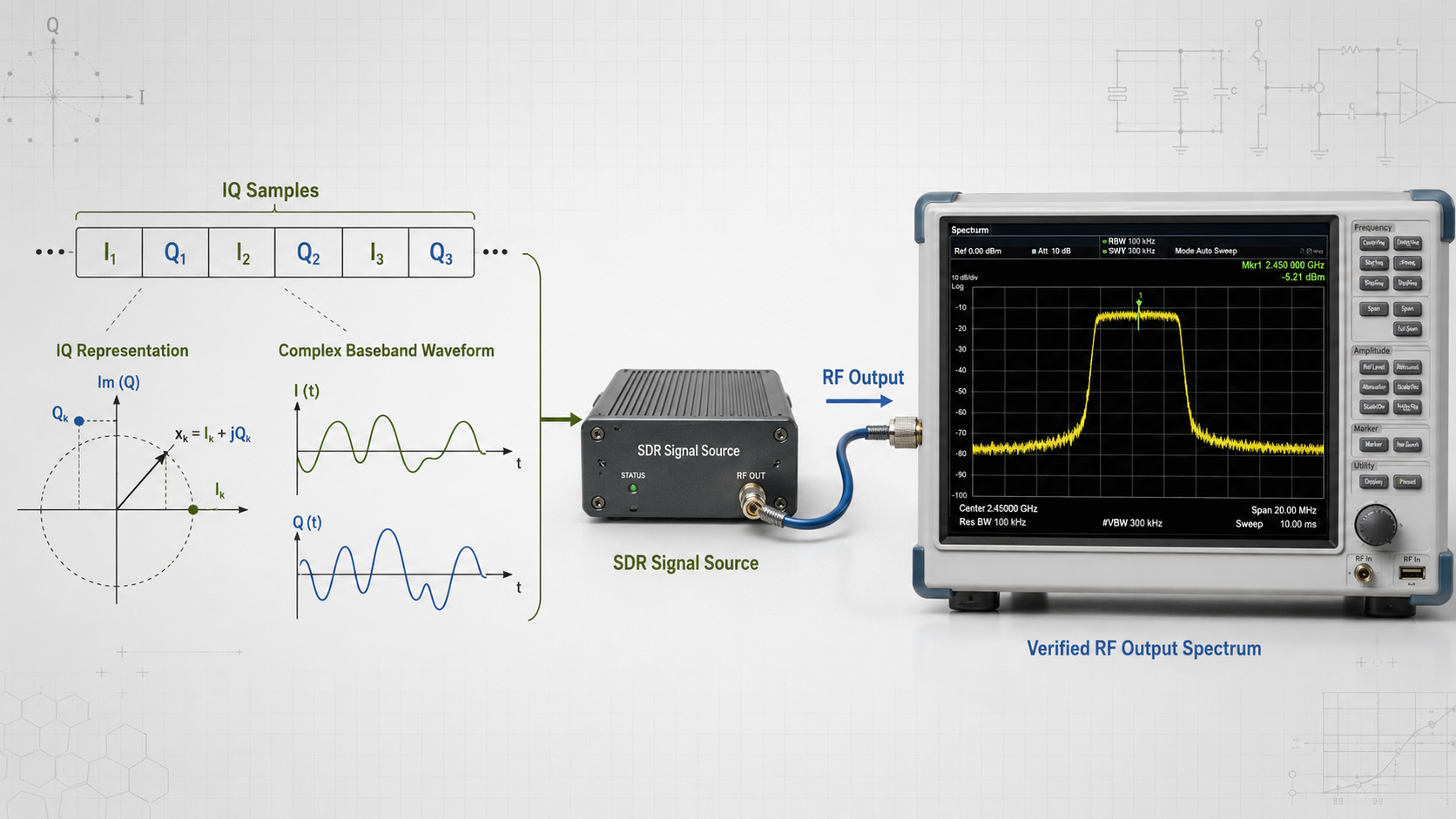
What is IQ data, and how can a file of paired numbers become an RF waveform? A custom .sc16 file loaded into an HZS1006000-F1 does not contain the final RF carrier. It stores a sequence of paired 16-bit I and Q values that describes a baseband waveform.
After the SDR reads those samples and applies the configured bandwidth, center frequency, and output gain, the digital description becomes a controllable RF waveform between 100 MHz and 6 GHz.
The key is to separate the waveform from its RF placement. IQ samples describe how amplitude and phase change over time. The SDR processes that description and places it at the required RF center frequency.
Problems begin when file format, IQ sample rate, occupied bandwidth, center frequency, and gain are treated as interchangeable settings. A file may load successfully but still play at the wrong speed, appear mirrored, become clipped, or produce an unexpected spectrum.
Quick answer: IQ stands for In-Phase and Quadrature. Each sample contains two coordinated values that describe one point in a complex waveform. An SDR transmitter reads the samples, filters and converts them, and places the waveform at a selected RF center frequency.
IQ data is a sequence of digital sample pairs used to describe how a signal changes over time.
The I component means In-Phase. The Q component means Quadrature, a second signal direction positioned 90 degrees from I.
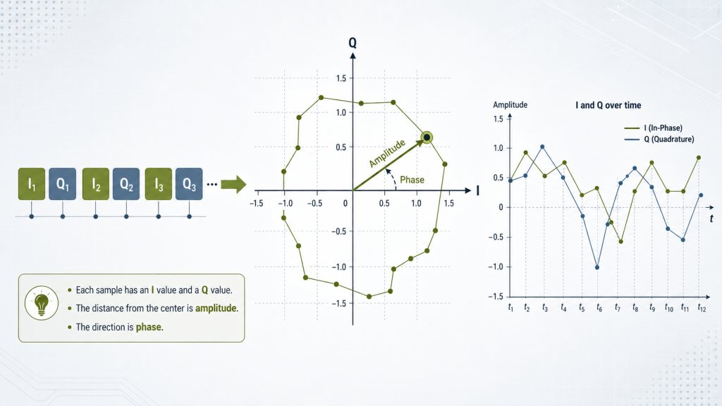
At each sample time, the waveform contains:
Together, they describe one point in the complex signal plane.
The distance of that point from the center represents signal amplitude. Its direction represents signal phase. As the samples change, the waveform can vary in amplitude, rotate in phase, shift in frequency, or move through a digital modulation pattern.
One IQ sample can be represented as:
I + jQ
The letter j identifies the quadrature component.
IQ data usually represents a waveform around baseband rather than storing the final RF carrier inside every sample. The same baseband sequence can therefore be placed at different supported RF frequencies by changing the SDR center-frequency setting.
In a signed 16-bit complex workflow, each sample contains one signed I value followed by one signed Q value. The SDR reads that sequence and reconstructs the intended waveform behavior.
One value can describe movement along a line. Two perpendicular values can describe movement in any direction across a plane.
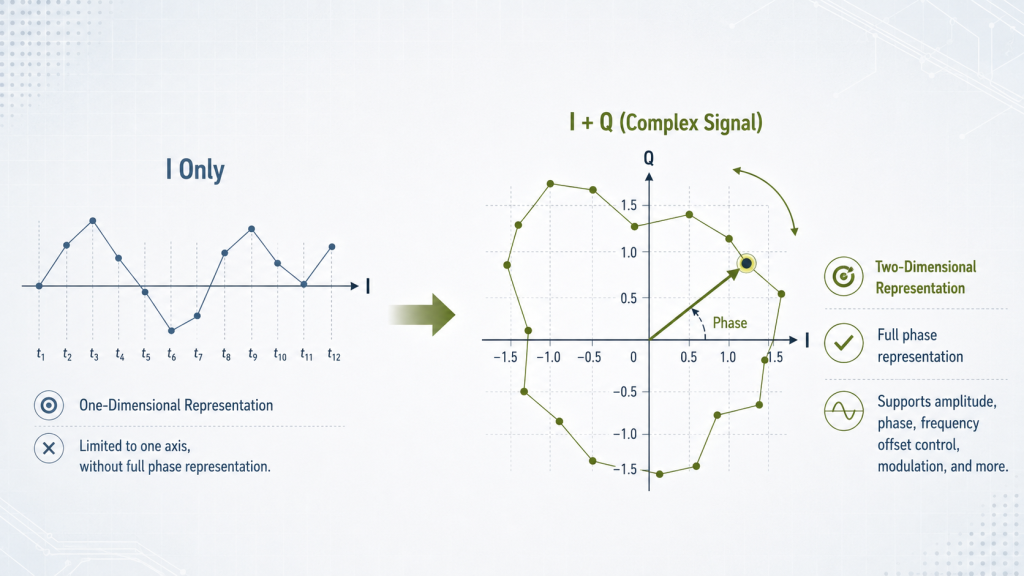
A simple comparison is a coordinate map:
Using only I would restrict the waveform to one axis. Adding Q allows the signal to represent all phase directions.
IQ data can describe:
If an IQ point rotates around the center at a constant rate, it represents a frequency offset from baseband. If it moves between defined positions, it may represent digital modulation symbols. If its distance from the center changes, the amplitude changes.
Within the limits of its converters, processing bandwidth, and RF front end, an SDR can generate different waveform structures by changing the IQ data and playback configuration.
The hardware provides the conversion platform. The IQ sequence defines how the waveform changes.
.sc16 IQ File?A .sc16 file commonly stores signed, complex, 16-bit IQ data.
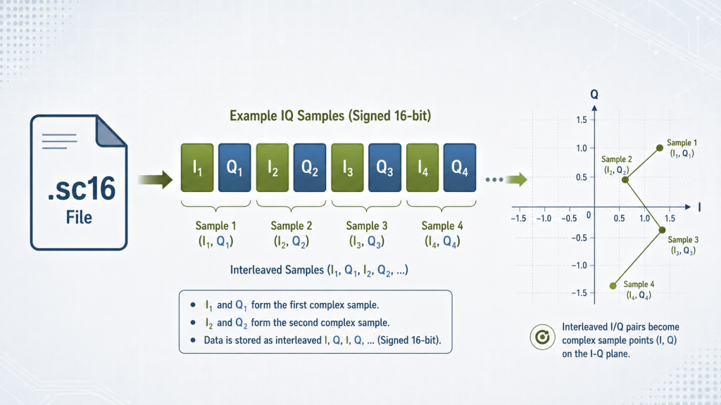
The samples are arranged as an interleaved sequence:
I1, Q1, I2, Q2, I3, Q3...
I1 and Q1 belong to the first sample point. I2 and Q2 belong to the next point.
In the documented HZS1006000-F1 workflow, a custom filename follows this structure:
name_0m.sc16
The filename identifies the waveform and allows the module to recognize the file. It does not define every playback condition.
The system must still apply the correct:
This is why two files with the same .sc16 extension are not automatically interchangeable.
Compatibility also depends on:
Changing the filename cannot correct a different sample type, byte order, I/Q sequence, or playback rate.
The practical rule is:
Treat an IQ file as a complete digital interface definition, not only as a file extension.
A custom IQ waveform moves through several digital and RF stages before it appears at the output connector.
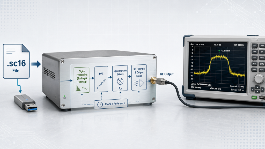
The waveform is first generated as a compatible sequence of signed 16-bit I and Q samples.
The engineer should define:
The waveform file is then named using the structure recognized by the module.
In the documented HZS1006000-F1 workflow, the prepared .sc16 file is copied through the module’s USB-accessible storage.
After the file is transferred, the waveform list is updated and the module is restarted so the new waveform can be selected for playback.
A file copied incompletely or placed outside the required workflow may not appear in the available waveform list.
The engineer then sets the required operating parameters:
These settings do not replace the IQ data.
The IQ file defines the internal waveform structure. The center-frequency setting determines where that structure appears in the RF spectrum. Gain affects the output level.
Conceptually, an SDR transmitter processes the samples through digital scaling, filtering, analog conversion, and RF frequency placement.
The simplified path is:
Custom .sc16 file → digital processing → analog conversion → RF frequency placement → RF output
The file itself does not contain a 2.4 GHz, 5.8 GHz, or other final RF carrier. The SDR creates that placement during transmission.
The source is therefore doing more than reading a file. It is converting a digital waveform description into configurable RF output.
One of the most common IQ integration mistakes is treating sample rate, occupied bandwidth, instantaneous bandwidth, and center frequency as the same parameter.
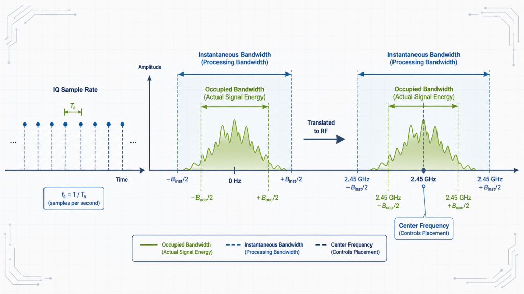
They describe different parts of the waveform and hardware.
| Parameter | What it controls | What it does not define |
|---|---|---|
| IQ sample rate | How many IQ sample pairs are processed each second | Final RF center frequency |
| Occupied bandwidth | How much spectrum the waveform actually uses | Complete IQ sample rate |
| Instantaneous bandwidth | How much bandwidth the SDR can generate at one time | Full RF tuning range |
| Center frequency | Where the waveform appears in the RF spectrum | Modulation structure |
IQ sample rate defines how quickly the digital samples are processed.
If a file prepared for one rate is played at another, the waveform timing changes. Internal frequency offsets and occupied bandwidth also scale with the rate.
For example, a waveform created for 100 MS/s but played at 50 MS/s runs at half the intended time scale. Its frequency offsets and occupied bandwidth also become narrower.
The file may still load correctly, but the RF result will not match the original design.
Occupied bandwidth is the part of the spectrum that contains the intended signal energy.
It depends on:
A 100 MS/s IQ file does not automatically produce a 100 MHz-wide signal. It may contain a much narrower waveform.
Instantaneous bandwidth defines the maximum waveform span the SDR can generate at one time.
The HZS1006000-F1 supports up to 200 MHz real-time bandwidth. This is a hardware boundary, not a requirement that every waveform occupy 200 MHz.
Frequency coverage answers:
Where can the SDR place the waveform?
Instantaneous bandwidth answers:
How wide can the current waveform be?
Center frequency determines where the baseband waveform is positioned in the RF spectrum.
For example, a configuration using a 2.45 GHz center frequency and 150 MHz bandwidth defines an approximate configured region from 2.375 GHz to 2.525 GHz.
That does not mean useful signal energy fills the entire region. The actual occupied bandwidth still depends on the IQ waveform.
The distinction is:
A file can be recognized by the SDR and still produce the wrong RF result.
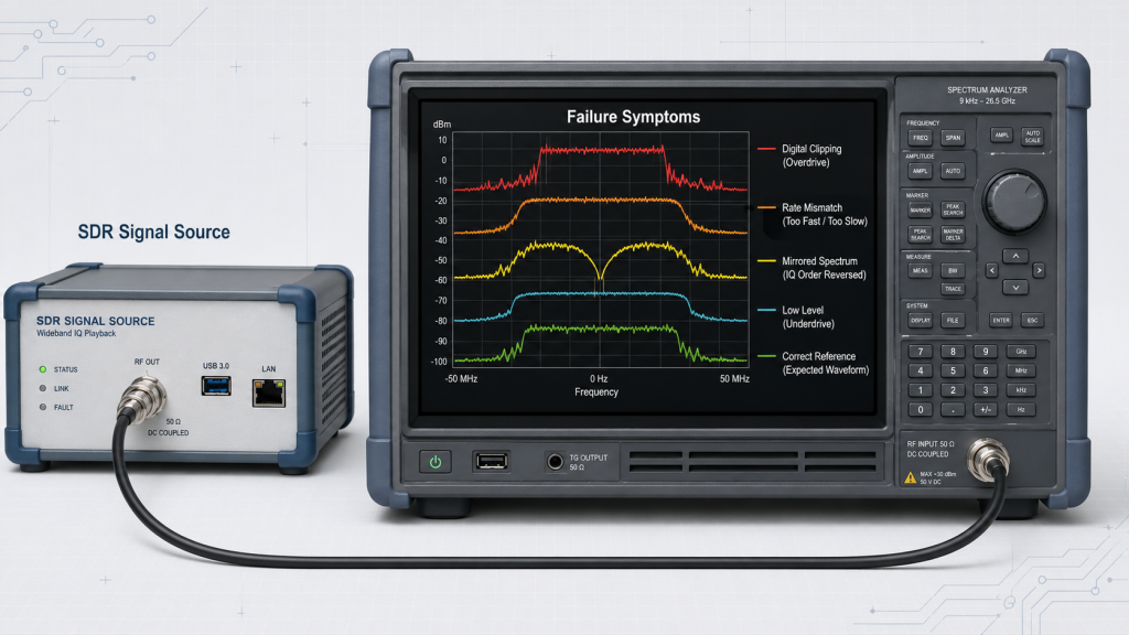
| Symptom | Likely cause | What to verify |
|---|---|---|
| Waveform plays too fast or too slowly | Sample-rate mismatch | File generation rate and SDR playback rate |
| Bandwidth is wider or narrower than expected | Incorrect sample rate or filtering | Sample rate, filtering, and occupied bandwidth |
| Spectrum appears mirrored | I/Q reversal or sign error | I/Q order, sign convention, and byte order |
| Spectrum is distorted | Digital clipping | Peak values, scaling, gain, and headroom |
| RF output is lower than expected | Low digital level or gain setting | IQ amplitude and module output setting |
| File is not recognized | Naming or format mismatch | Filename, extension, data type, and loading workflow |
If the SDR uses a different sample rate from the one assumed during waveform generation, the timing changes.
The first question should be:
Was the waveform generated and played using the same IQ sample rate?
A mirrored spectrum may result from:
The signal may still appear near the correct center frequency. Checking only total power or center frequency may therefore miss the problem.
Clipping occurs when sample peaks exceed the available numerical range.
Possible results include:
Multi-carrier and high peak-to-average waveforms require digital headroom. Scaling every sample close to the 16-bit limit may increase the digital level while reducing spectral quality.
Conservative IQ scaling may preserve the correct waveform shape while producing less RF output than expected.
Increasing module gain may raise the output level, but IQ scaling and RF gain are different controls. Both must remain within the required operating boundary.
The SDR produces configurable low-power RF output. A downstream amplifier responds to the actual RF power at its input after the gain and loss of cables, filters, switches, attenuators, connectors, and driver stages are included. Too little drive may prevent the PA from reaching target output, while excessive drive may push it toward compression, higher current, heat, and distortion.
A broader system-level explanation is available in the drone signal jamming system guide. Engineers matching the source to an amplifier should also review SDR output and RF PA input drive requirements.
Successful playback depends on the waveform file and SDR configuration using the same interface definition.
| Check item | Required information |
|---|---|
| Filename | Structure recognized by the module |
| Data type | Signed 16-bit complex IQ |
| Sample order | I1, Q1, I2, Q2... |
| Byte order | Required endianness |
| IQ sample rate | Rate used for generation and playback |
| Occupied bandwidth | Intended spectral width |
| Digital scaling | Peak values, normalization, and headroom |
| Center frequency | Required RF position |
| Configured bandwidth | Playback bandwidth |
| Output gain | Initial setting and adjustment range |
| Playback behavior | Selection, looping, startup, stop, and restart |
| RF verification | Spectrum, bandwidth, level, and unwanted components |
Which SDR Signal Source Fits the IQ Workflow?
Once the IQ file and playback conditions are defined, the next step is to confirm whether the SDR architecture supports the required upload workflow, bandwidth, RF outputs, control interface, and operating environment.

CUSTOM IQ / CASCADING ROUTE
A stronger starting point when the system needs custom IQ loading, up to 200 MHz real-time bandwidth, RS422 AT-command control, and documented multi-unit cascading.

DUAL RF OUTPUT / WIDE TEMPERATURE ROUTE
A stronger starting point when two independent SMA outputs, up to 100 MHz per channel, a 9-32 V supply range, and wider operating temperature coverage are priorities.
Selection Condition HZS1006000-F1 HZSDR1006000-A01 Frequency Coverage 100 MHz–6 GHz 100 MHz–6 GHz Real-Time Bandwidth Up to 200 MHz Up to 100 MHz per channel; 200 MHz combined RF Output Architecture Dual-PHY internal architecture with one documented external SMA output; confirm PHY-to-port routing. Two independent SMA RF outputs Custom IQ Support USB upload of 16-bit complex IQ files; confirm the current .sc16/.cs16naming convention.Not documented in the current manual; confirm by RFQ. Expansion RS422 cascading of up to 10 units Multi-module addressing and control supported; maximum quantity confirm by RFQ. Control RS422 AT-command control; customer application development supported RS422 host control; custom API availability confirm by RFQ. Supply 28-32 V DC 9-32 V DC Operating Temperature 0°C to 50°C −40°C to +70°C Before RFQ: Confirm final firmware, physical RF-port routing, IQ-file convention, control/API availability, expansion limits, and the approved product revision.
I means In-Phase and Q means Quadrature. They are two perpendicular components that together describe signal amplitude and phase at each sample point.
No. IQ data is a sampled digital description of a waveform. The SDR processes the samples and places the resulting waveform at the selected RF center frequency.
.sc16 mean?It commonly refers to signed, 16-bit complex IQ samples arranged as interleaved values such as I1, Q1, I2, Q2....
.sc16 file produce the intended RF waveform?The file must use the correct data structure, I/Q order, byte order, sample rate, scaling, bandwidth, and playback configuration.
IQ sample rate defines how quickly the digital samples are processed. Center frequency determines where the resulting waveform is placed in the RF spectrum.
IQ data is a digital representation of how a waveform’s amplitude and phase change over time. An SDR reads the I and Q samples, processes the waveform, and places it at the required RF center frequency.
Successful playback depends on a complete match between the digital file, playback timing, spectral occupancy, output configuration, and downstream RF interface. Loading a recognized file is only the first step; the final waveform must also be verified at the RF output.
RF SKYPOWER can review your IQ file format, sample rate, intended bandwidth, center-frequency range, digital scaling, playback behavior, and required RF output level. Review the SDR module specifications or contact us today for an engineering compatibility review.