










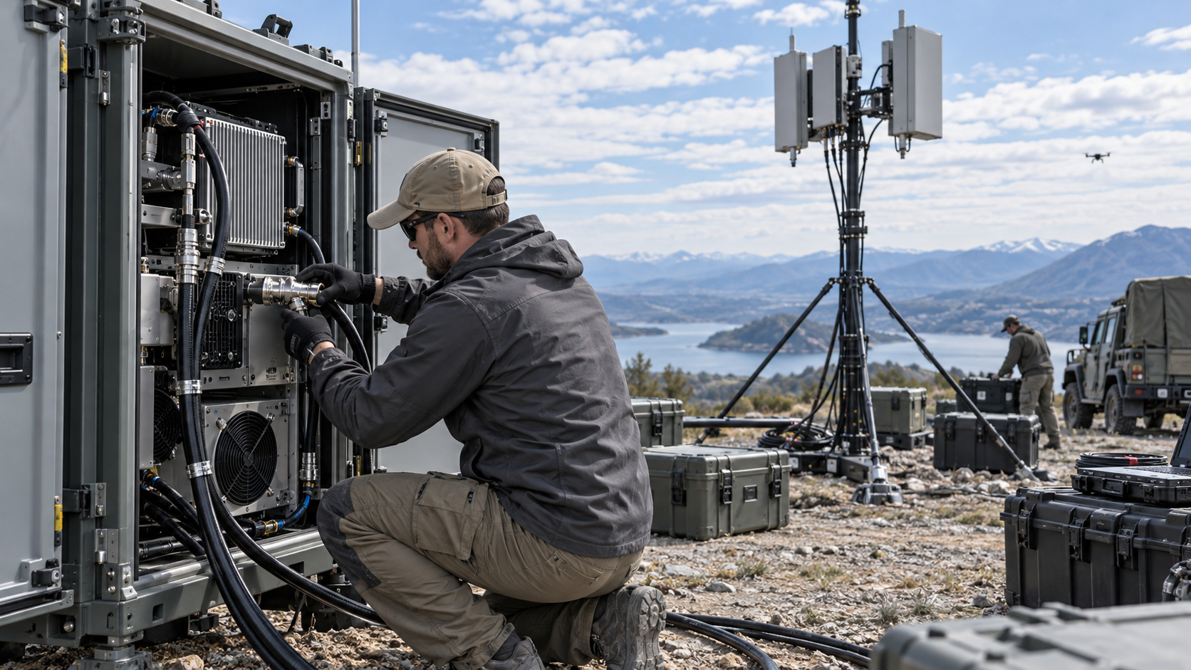
A temporary C-UAS RF chain can develop new risks after teardown and reassembly because cable connections, antenna paths, DC supply, and control interfaces may no longer match the tested configuration. Previous test results can still be reused, but only where their documented scope applies to the new setup. Any changed installation conditions may require separate verification.
A factory PA test measures the module under defined conditions. It does not verify the complete cable and antenna path installed at a temporary venue. Published specifications for RF Power Amplifier Modules establish equipment-level requirements, while the actual installation introduces additional interfaces.
A relocation does not necessarily require repeating every factory test. The first task is to identify what the previous acceptance covered, what changed, and which results still apply.
1. Why Does Each Temporary Setup Change the RF Acceptance Boundary?
An RF acceptance result applies to a defined configuration. Its validity depends on the components tested, the measurement reference planes, and the operating conditions recorded during the test.
Consider a C-UAS system installed at Venue A. The PA connects to an antenna through a specified feeder, with power and control provided by an established cabinet configuration. After the event, the equipment is transported to Venue B. The same PA and controller are reused, but the antenna moves, the feeder is replaced, and the system connects to a different power distribution arrangement.
The original factory report may still provide valid evidence about the PA. The new feeder, antenna connection, and DC supply introduce conditions that the previous site acceptance may not cover.
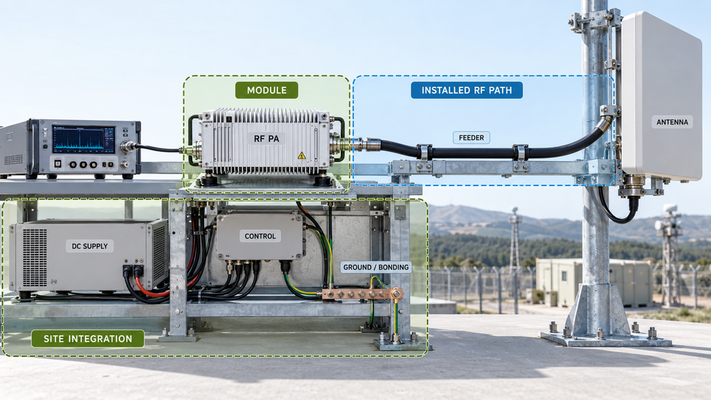
Three boundaries help separate the evidence:
- Module boundary: PA performance under documented test conditions.
- Installed RF path boundary: Cables, adapters, RF routing, and antenna connections.
- Site integration boundary: DC supply, control, grounding, mounting, cooling, and environmental conditions.
Each boundary requires evidence appropriate to its scope. A module report cannot establish the insertion loss of a replacement feeder, and a cable measurement cannot establish whether a reassigned control connection operates correctly.
The general relationships between the SDR, PA, supply, and antenna are covered in C-UAS RF chain integration. Temporary deployment adds a specific question: which conditions from the approved installation still apply today?
Every redeployment needs a configuration review. That review may lead to targeted checks rather than complete factory requalification. If the previous acceptance scope is unknown, its applicability must remain unresolved until the necessary evidence is available.
2. What Must Be Recorded Before a Temporary RF Chain Is Reassembled?
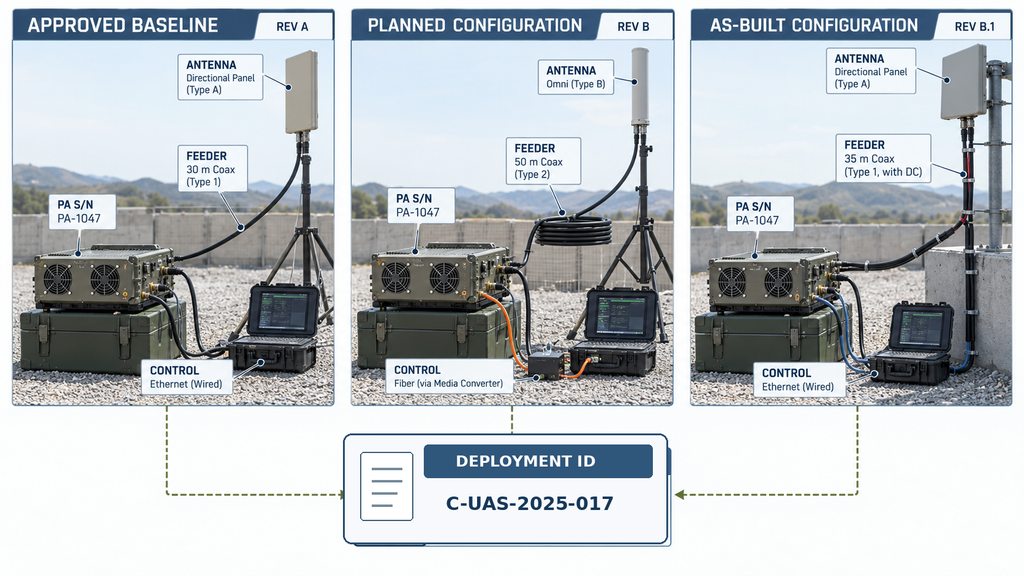
Before reassembly, identify the last approved configuration and document the intended setup. Record the deployment ID, venue, installation date, approved revision, equipment identities, and planned changes.
The baseline should identify the PA and relevant revisions, RF ports, feeder assemblies, adapters, antenna interfaces, and other components in the signal path. Critical connections must show which component belongs to which port.
Cable identity matters. Two cables may look identical but differ in length, construction, connector type, or frequency-dependent performance. Substituting one changes the RF path, even if the overall system diagram remains unchanged.
The planned configuration should also identify the DC connection, grounding arrangements, control interface, relevant settings, and antenna mounting.
After reassembly, record the actual installed configuration and compare it with the approved baseline. Capture component substitutions, actual connections, control settings, and deviations introduced during installation.
Keep three records distinct:
- Approved baseline: Equipment and interfaces covered by the previous acceptance.
- Planned configuration: Intended equipment, connections, and changes before installation.
- As-built configuration: Actual connections and settings verified after installation.
Link all three to the deployment ID and configuration revisions. This prevents a report from one event from being mistaken for evidence covering another setup.
Photographs and connection drawings can confirm physical arrangements, but they do not prove RF performance. A photograph may identify a feeder connection; it cannot establish that feeder’s insertion loss or return loss.
Multi-PA cabinets with switching or shared routing may also require a verified port map. Cabinet RF routing verification covers the detailed checks for those internal paths.
The result should be a traceable record of what changed. If a critical component, connection, or configuration revision cannot be identified, the team must resolve that gap before treating the installations as equivalent.
3. How to Check Cables, Adapters, and Antenna Connections After Reassembly
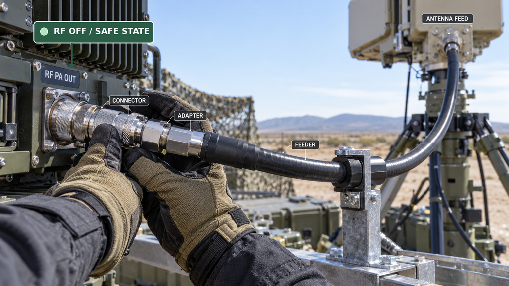
Temporary installations involve repeated connector mating, cable handling, transport, and changes in mechanical support. These activities can affect the RF path even when the major equipment remains unchanged.
Before inspecting or reconnecting RF interfaces, place the equipment in its approved safe state, verify that RF output is disabled, and isolate supplies where required by the maintenance procedure.
Start with the connectors. Check for contamination, visible damage, incorrect mating, poor support, and departures from the manufacturer’s tightening requirements. Repeated mating cycles do not prove failure, but a connector that appears engaged is not necessarily correctly assembled.
Examine coaxial cable routing for excessive bending, compression, unsupported weight, and transport damage. Use the manufacturer’s handling and minimum bend-radius requirements rather than a universal limit.
Temporary adapters introduce additional mating interfaces and may affect mismatch, insertion loss, or mechanical stress. Confirm their frequency and power suitability, connection condition, and effect on the installed path where verification is required.
Antenna connections also deserve attention. Relocation or changes in mounting and feed arrangements can alter the installed path. Outdoor venues may introduce different requirements for support, weather protection, and connector sealing.
Physical inspection cannot replace RF measurement. A continuity check may identify certain conductor faults, but it cannot establish frequency-dependent insertion loss or return loss.
Correct damaged, incompatible, or inadequately supported connections before accepting the affected path. Mechanically sound components can then proceed to the electrical checks required by the project.
The inspection should identify which connections need additional evidence, avoiding unnecessary replacement while preventing unverified paths from being accepted.
4. What DC, Grounding, and Control Checks Does a New Venue Require?
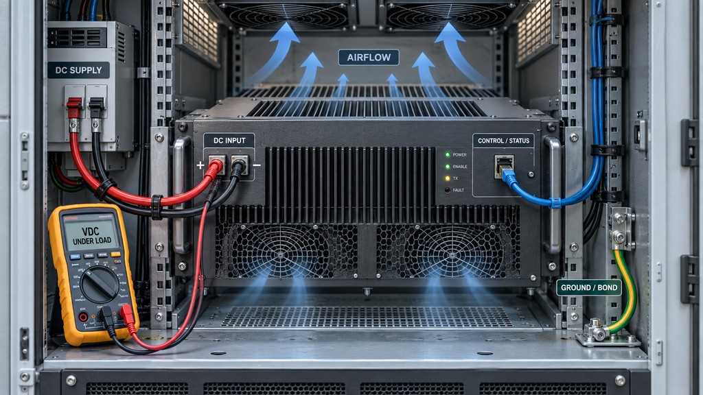
A relocated PA may encounter different power distribution, grounding arrangements, control wiring, and cooling conditions. These interfaces must meet the requirements of the current installation.
DC supply: Check the RF amplifier power supply requirements for the selected module, then verify the voltage at its specified input under the applicable load. The power supply’s displayed setting may differ from the voltage delivered under load because of cable resistance, connectors, and operating current.
Grounding and shielding: Review the installation against the approved site design. Different mounting surfaces and cable routes can alter bonding and shielding arrangements, although these changes alone do not prove electromagnetic interference.
Control: Where supported, verify RF amplifier enable control, command routing, and status feedback against the current wiring and configuration. A physically compatible connection may still have an incorrect address or mapping.
Cooling: Check whether the new cabinet position or temporary enclosure changes airflow, ambient conditions, or heat rejection. Previous thermal evidence remains applicable only within its documented scope.
The checks should follow the actual changes. A replaced control harness may require renewed mapping and feedback verification without requiring an unrelated RF factory test.
If critical supply, control, grounding, or cooling requirements remain unresolved, an acceptable RF measurement alone cannot support release of the complete installation.
Detailed power distribution, grounding design, and control-timing procedures belong to their respective engineering reviews.
5. How to Decide Which RF Measurements Must Be Repeated
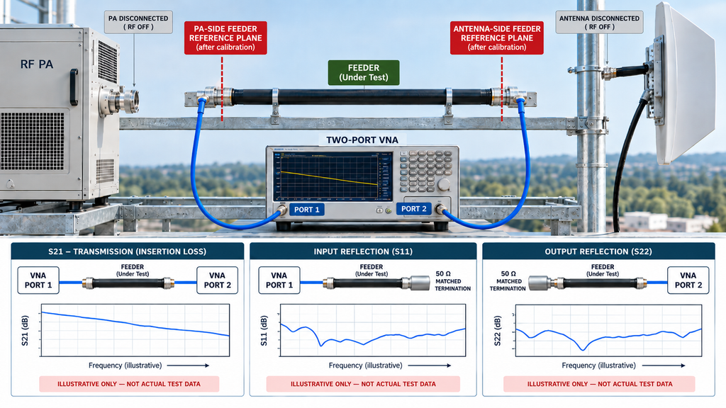
The required RF measurements depend on what changed and which earlier results remain applicable.
A replacement feeder may require renewed transmission-loss and reflection measurements. An additional RF adapter requires a suitability check and, where necessary, measurements of the affected path. A relocated antenna may require renewed verification of its connection and installed RF path.
Changes to DC or control interfaces require corresponding checks but do not independently justify repeating measurements of unaffected RF paths.
Measurement Location Changes the Meaning of the Result
Start with the reference plane. Power measured at the PA output connector and power measured at the antenna input describe different locations. Cable and component losses can make those values differ.
Insertion loss and reflection describe different properties. A feeder can have relatively low reflected power while introducing excessive transmission loss.
A low VSWR measured at the PA end does not necessarily confirm a low-loss feeder or well-matched antenna. Feeder attenuation reduces the reflected signal measured upstream because that signal experiences loss along both the outward and return paths.
The engineering team therefore needs to identify the affected RF property and its measurement reference plane.
Historical and current results are directly comparable only when the relevant frequency, reference plane, load, operating state, test method, and correction assumptions are sufficiently aligned. Single-frequency measurements do not establish full-band compliance, while different thermal or drive conditions may prevent direct comparison.
Powered RF checks must use suitable rated equipment, approved loading conditions, and authorized test procedures. The differences between controlled loads and installed antenna paths are addressed in dummy load and real antenna chain checks.
For each changed path, define the required measurement, applicable conditions, and acceptance evidence. If those details are unavailable, leave the corresponding performance decision open.
6. When Can Previous RF Test Evidence Be Reused?
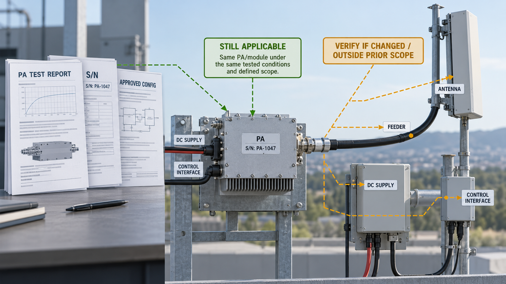
Previous RF test evidence remains useful when its equipment identity, configuration, measurement scope, and operating conditions still apply.
Relocation alone does not invalidate every result. However, handling damage, repairs, hardware modifications, or different operating conditions may affect the relevance of the original report.
A serial-number-linked RF amplifier test report identifies the tested unit and records its performance under specified conditions. If the module remains unchanged and suitable for those conditions, its earlier evidence may still apply.
Replacing a feeder does not invalidate the original PA measurement, but it creates a new question about the installed RF path. If the PA itself has been repaired, damaged, or modified, the engineering team may need additional evidence of its current condition.
Redeployment Configuration Change and Verification Decision Matrix
The following examples show how installation changes affect previous evidence. All statuses are pending because no actual field measurements or completed deployment records are provided.
| Configuration change | Potentially affected boundary | Earlier evidence that may still apply | New check or evidence required | Responsible party | Decision status |
|---|---|---|---|---|---|
| Same PA, replacement feeder cable | Installed RF transmission path | Applicable PA-level test record, subject to the module’s current condition | Identify the cable and verify relevant path loss and reflection | RF integration engineer | Pending affected-path verification |
| Additional RF adapter | Connector interfaces and path performance | Evidence for unchanged modules and components | Verify adapter suitability, connection condition, and affected path where required | Installation and RF test team | Pending added-interface review |
| Different venue DC supply | PA input supply and operating state | Applicable module specifications and previous module results | Verify supply conditions at the PA interface under the specified load | Electrical integration engineer | Pending site-supply verification |
| Antenna replaced or relocated | Antenna interface and installed RF path | Relevant unchanged PA-level results | Verify the current antenna configuration and required path performance | Antenna and RF integration team | Pending installed-antenna verification |
| Control harness or port reassigned | Control identity, enable, and status feedback | Applicable module interface specifications and unaffected RF results | Confirm control mapping, configuration, enable conditions, and feedback | Control integration engineer | Pending control-interface verification |
Each pending status must be resolved against the project’s approved requirements and supported by traceable records. Satisfactory evidence permits the relevant item to be marked verified; a failed requirement calls for corrective action; missing evidence leaves the decision open.
This approach preserves valid historical evidence without extending it to changed conditions. It also avoids unnecessary retesting of unaffected equipment.
Comparison requires sufficiently aligned frequency, reference plane, load, thermal state, operating conditions, and test method. Where these differ, identify the missing information before making a performance judgment.
A serial-number-linked report must match the relevant equipment revision and test scope. Representative sample results cannot establish the performance of every delivered unit, and factory module tests do not certify a new site installation.
Changes affecting antenna matching or reflected power may need further assessment. RF PA VSWR field failure prevention covers that specific risk.
The final evidence review should identify which records remain applicable, which additional checks are complete, and which issues still prevent acceptance.
7. What Belongs in a Temporary C-UAS Redeployment Checklist?
A useful checklist must be tied to a specific deployment. It should identify the installed configuration, supporting evidence, unresolved issues, and person responsible for the release decision.
Deployment record
- Deployment ID / venue / installation date
- Previously approved configuration revision
- Current as-built configuration revision
- Previous acceptance record
- Assigned engineering reviewer
Temporary C-UAS Redeployment Release Checklist
For each of the six checks below, record the evidence reference, verification status, responsible owner, and any outstanding action in the deployment log.
- C1 — Configuration identity. Verify PA and equipment identities, revisions, RF ports, cable assemblies, antenna configuration, and control settings against the approved baseline. Evidence: current connection record and documented configuration differences.
- C2 — Physical RF connections. Inspect cables, connectors, adapters, mechanical support, and antenna feed connections. Evidence: installation inspection record and applicable component specifications.
- C3 — DC supply, grounding, and control. Verify supply conditions, grounding and bonding requirements, control connections, configuration, and required status feedback. Evidence: interface requirements and current verification records.
- C4 — RF measurement boundaries. Confirm the affected paths and required loss, reflection, or other RF measurements. Evidence: test records identifying frequency, reference plane, load, operating conditions, and applicable acceptance criteria.
- C5 — Previous evidence applicability. Identify which earlier reports remain valid and which changes require additional verification. Evidence: historical report references, configuration comparison, and supplementary test records.
- C6 — Release responsibility and authorization. Confirm mandatory requirements, resolution of critical exceptions, and applicable site authorization. Evidence: completed checks, exception dispositions, and designated approval.
Shared record for every check (C1–C6):
Check ID | Evidence record ID / file reference | Status | Responsible owner | Exception / follow-up action
Each item must have its own record using these fields. The shared format avoids repeating the same blank fields six times while retaining traceability.
Use one of three inspection statuses:
- Verified: The requirement is satisfied and supported by identifiable evidence.
- Pending Verification: Required checks, evidence, or issue resolution remain incomplete.
- Not Applicable: The item falls outside the approved scope, with a documented justification. Mandatory requirements cannot be bypassed.
Final Release Record
- Deployment ID and approved configuration revision
- Outstanding exceptions and their disposition
- Not Applicable justifications and record references
- Final decision: Approved / On Hold / Not Approved
- Authorized approver, approval date, and supporting record reference
Approved means mandatory requirements are satisfied and the designated authority authorizes the installation. On Hold means verification, evidence, or authorization remains incomplete. Not Approved means a mandatory condition has failed and the installation has not been accepted.
Release approval must refer to the current deployment and its evidence. A checklist from a previous venue cannot replace that record.
An unresolved item may reflect missing measurements, incomplete configuration records, or an actual equipment problem. The responsible engineer must establish which before deciding on corrective action or replacement.
This checklist supports the engineering review. The project’s formal acceptance procedure, safety requirements, and applicable RF operating authorization remain controlling.
Conclusion
Temporary C-UAS deployments create RF chain risks because teardown, transport, and reassembly can change cable and antenna connections, supply and control interfaces, and installation conditions. Previous tests may no longer cover those changes, even when the same equipment is reused.
Can a temporary C-UAS RF chain reuse its last test? Yes, where the previous evidence still applies to the current equipment, configuration, and operating conditions. Unchanged module-level results may remain valid within their documented scope. Changed interfaces require verification according to project requirements.
A relocation does not necessarily require repeating every factory test. The engineering team must establish whether the existing evidence covers the current installation. Project-specific limits, equipment suitability, and formal acceptance still depend on the applicable requirements and measurements.
Before redeployment, compare the current configuration with the approved baseline, record changes, identify applicable reports, complete the necessary checks, and obtain release approval.
For RF PA interface or documentation review, provide RF SKYPOWER‘s engineering team with the intended frequency and operating conditions, module interfaces, DC and control requirements, cable and antenna connections, planned deployment configuration, and relevant historical records. These details support module-level engineering and RFQ review while the authorized project team retains responsibility for site acceptance.