










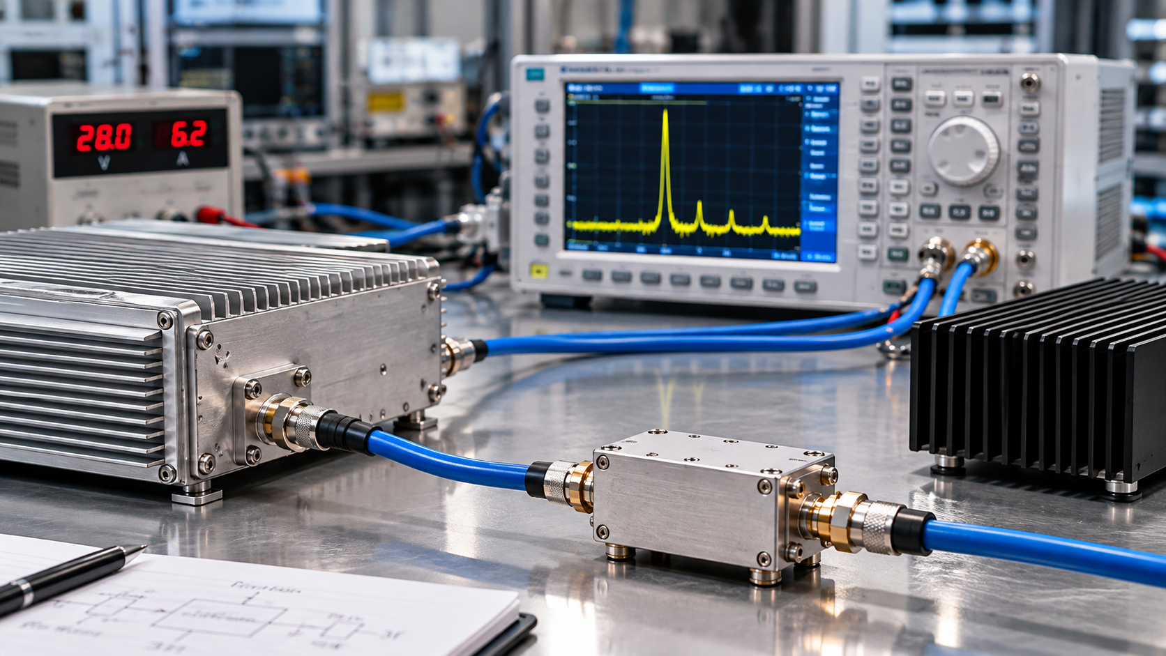
Define C-UAS RF chain harmonic filtering at the measurement reference plane where the limit applies, and assign responsibility to the party delivering and accepting that part of the RF chain. A supplier providing a bare power-amplifier (PA) module is accountable for its agreed PA-port specification; a filtered assembly or installed system needs separate evidence covering the components and interfaces included in that delivery.
The assignment changes if the PA supplier also provides the output filter or a complete filtered assembly. Without an agreed limit, filter scope, operating condition, and reference plane, an otherwise convincing spectrum trace cannot settle who must correct a harmonic problem. The engineering decision begins by defining the result that each party is actually expected to prove.
1. Define the Harmonic Limit at the Actual Acceptance Reference Plane
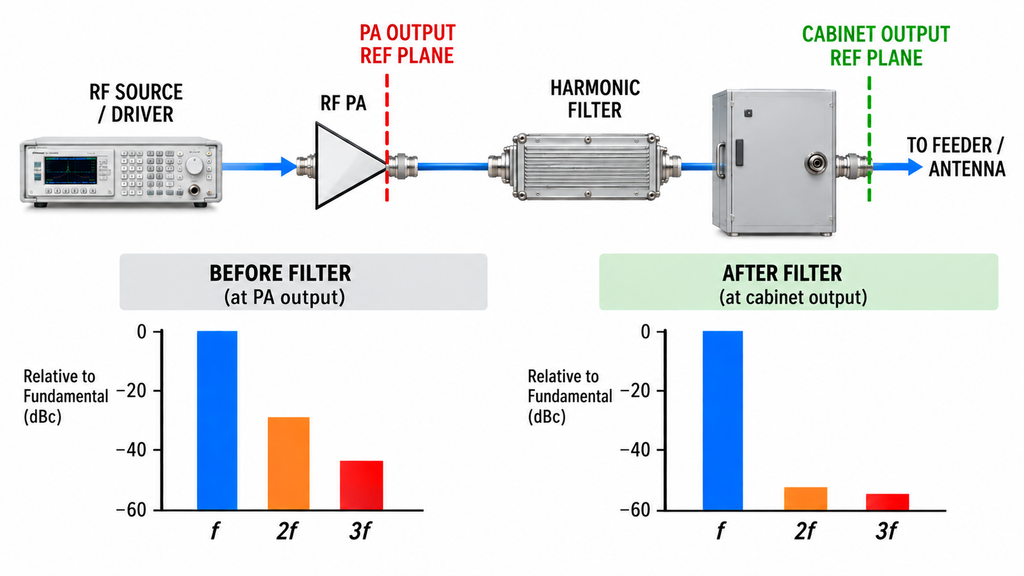
A requirement such as “harmonics below the limit” is not ready for a supplier quotation or acceptance test. At minimum, it must say which harmonic components are restricted, the limit format, and the connector or system boundary where the result will be judged.
The fundamental frequency is often written as f, so the second and third harmonics occur at 2f and 3f. Those are frequency relationships, not a universal list of required tests. A project operating at several fundamental frequencies must identify the resulting harmonic frequencies and any other components covered by its approved requirement. A filter that rejects one harmonic frequency does not automatically have the same response at another.
Specify whether the required limit is an absolute conducted level in dBm, a level relative to a defined fundamental in dBc, or a waveform-specific measurement defined by the acceptance procedure. For a stable discrete continuous-wave (CW) signal, a dBc result compares the corrected harmonic and corrected fundamental levels referred to the same declared plane. A pulsed, modulated, or noise-like signal may require a different measurement bandwidth or power definition. Those results should not be treated as interchangeable marker readings.
The reference plane is just as important as the unit. A reading at the spectrum analyzer input is not automatically a PA-output value. A filter-output measurement is not an antenna-feed measurement. Each needs its own sampling path and any applicable frequency-dependent correction. Harmonic measurement settings and reference-plane corrections belong to the dedicated measurement procedure; the present decision is which boundary that procedure must substantiate.
Before anyone assigns a pass or failure, the requirement owner should record the operating frequency, harmonic frequency or order, waveform, required RF output state, limit and units, fundamental reference when applicable, load, relevant thermal condition, measurement method, and reference plane. If the limit or its plane is missing, hold the acceptance judgment. A numerical result with no defined location cannot establish which supplier’s obligation has been met.
2. Separate Source, PA, Filter, and System Responsibilities
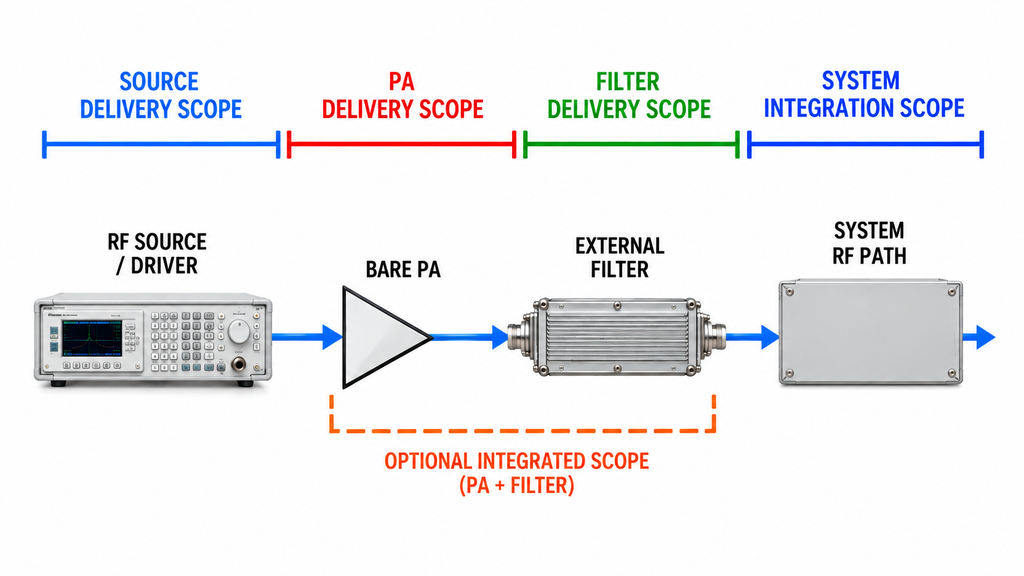
A C-UAS transmitter may place a signal source or SDR, a driver, a PA, an output filter, switching hardware, cables, and an antenna along the same RF path. Physical sequence explains how energy travels; it does not by itself establish contractual responsibility. The equipment schedule and interface specification must say what each party delivers and what it agrees to verify.
The source or driver provider needs to characterize the RF presented at the defined PA input, including unwanted components already present there. The PA supplier’s bare-module evidence concerns the conditions and output limits specified at the PA output reference plane. An external filter can attenuate certain spectral components downstream, but its attenuation cannot retroactively demonstrate that the unfiltered PA met a different PA-port specification.
For a separately supplied filter, the filter supplier may provide frequency-response, power-handling, matching, and environmental data while the integrator remains responsible for installing and checking the resulting combination. If the PA supplier delivers a filter as part of an approved integrated assembly, that supplier’s deliverable may instead include the filtered-output result. The contract should identify this scope explicitly; neither arrangement is automatically universal.
Beyond the filtered assembly, the cabinet and system owner must account for the interfaces actually under its control. Switching paths, additional cable loss, simultaneous channels, and the installed antenna environment can create questions that a single module report does not answer. Responsibility for a final system or regulatory acceptance result belongs to the designated system or approval authority under the applicable requirements, not automatically to the component manufacturer.
The handoff record should therefore name the physical output plane and the responsible organization for each promised result. If drawings and the purchase specification disagree about whether the filter is included, reconcile that delivery boundary before signing an acceptance statement. Diagnosing the origin of an unexpected line is a separate task; identifying source and PA contributions through a controlled spur-isolation comparison can support that investigation without deciding the contract by itself.
3. Decide Where the Filter Goes and What It Cannot Correct
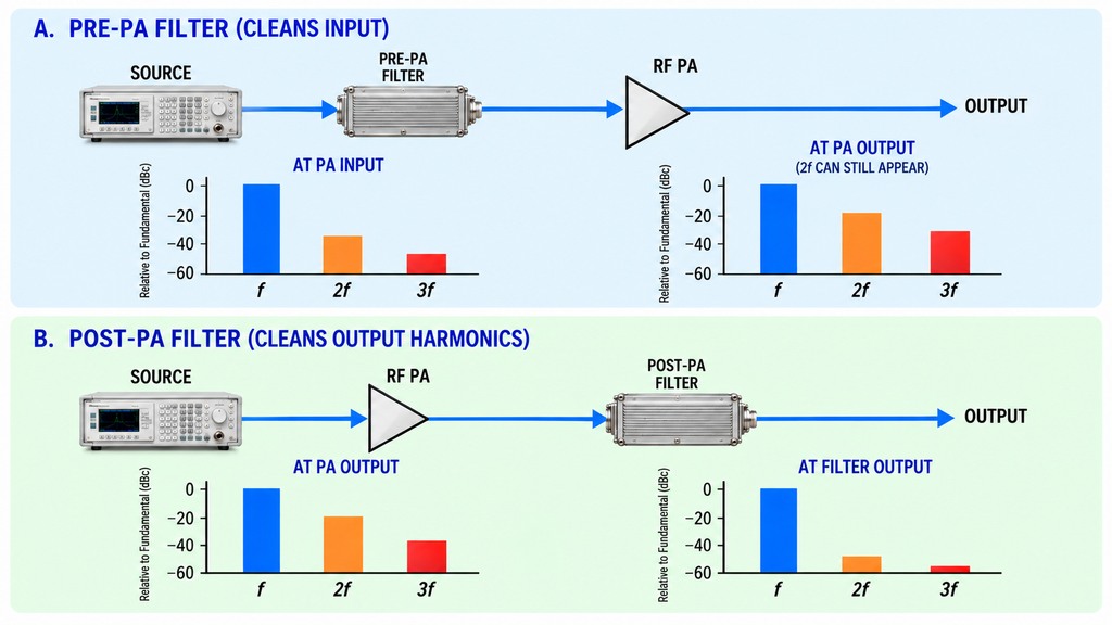
A filter before the PA and a filter after it serve different purposes. Conditioning the source or driver output can reduce unwanted input components before they reach the amplifier. It cannot remove a harmonic subsequently generated by the PA’s own nonlinear behavior. When the accepted limit is specified downstream of the amplifier, the architecture must address what appears at that downstream reference plane.
A post-PA filter may be considered when its passband preserves the required operating signals and its rejection covers the harmonic frequencies of concern. Whether it is built into the PA assembly, supplied separately, or incorporated in a switched RF route changes who must furnish the filter data and the filtered-output test. It also changes which connector marks the delivered boundary. Document the active filter path rather than calling every downstream result a generic “PA output.”
Filtering is not a universal repair for every spectral defect. Harmonics are integer multiples of a fundamental; spurious lines, intermodulation products, and spectral regrowth can have other frequency relationships. Unwanted energy that falls within a required passband may not be removable by a filter without affecting the intended signal. In a multiband chain, a harmonic associated with one operating mode can even fall inside a band that another mode must pass.
For these reasons, choose a candidate filter location only after linking the required waveform, harmonic frequencies, filter state, and limit plane. If the required frequencies are not known, or the proposed filter cannot be associated with the active RF path, the filter-location decision is not ready to freeze. Protected-radio coexistence is another downstream question; it needs its own verification rather than a conclusion based solely on filter placement.
4. Budget Passband Loss, Rejection, Power, and Matching Together
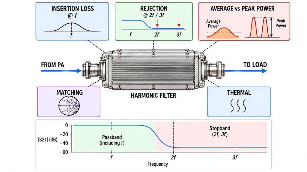
A filter should not be accepted from its stopband attenuation alone. Suppressing a harmonic while losing too much wanted-band output can leave the complete RF chain short of its project requirement.
Define the minimum usable output at the specified downstream plane, then account for the loss between that plane and the PA port. Filter passband insertion loss, switches, couplers, connectors, and feeders may all contribute. An unfiltered PA-output result is not the delivered power after those components. Conversely, adjusting the PA drive to recover loss changes the operating point and can change the spectrum, heat, and protection state. The comparison must identify whether drive was fixed or adjusted.
Rejection must be supported at the actual harmonic frequencies, not inferred from a nominal response at the carrier or a different band. The relevant response may change near a transition region or when another filter is switched into the path. The filter’s permitted average and peak RF power, duty cycle, thermal condition, and load or return-loss limits also matter. A frequency-response plot measured at low power does not, by itself, demonstrate acceptable performance under the intended high-power operating state.
The acceptance package should connect the required passband output, filter insertion loss, harmonic rejection, power rating, matching behavior, thermal condition, and interface configuration. If a supplier provides only one attenuation number without the operating frequencies or permitted power condition, there is not yet enough evidence to approve that filter for this RF chain. The broader broadband PA operating and spectral requirements remain a separate selection question; here, those data define what each party must demonstrate at the filter interface.
5. Test the Unfiltered PA and Filtered Assembly Separately
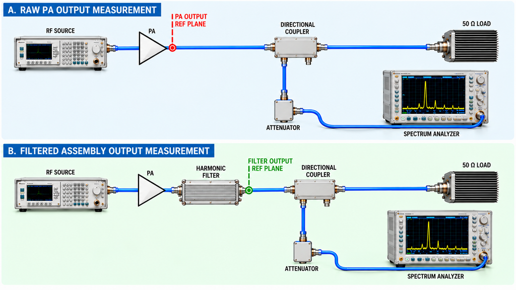
A filtered-output result and an unfiltered PA-port result are two different tests, even when taken during the same bench session. To interpret their relationship, the test engineer first needs an understood source baseline at the PA input and a valid measurement setup.
The source baseline establishes whether a suspicious harmonic or spur is already presented to the amplifier. Measure the PA’s raw output at the agreed PA-output reference plane under the applicable input drive, waveform, load, DC condition, and thermal state. Then measure the filtered assembly at its separately declared output plane with the actual filter and route in place. Preserve the filter identity, hardware revision, and state for the second result. If those operating conditions change, the results may describe different tests rather than only the filter’s contribution.
For each measured spectral component, keep the analyzer’s raw reading distinct from the corrected level at the declared plane. A coupler, attenuator, cable, or fixture may have a different response at the fundamental and at 2f or 3f. Correction established at the carrier cannot simply be reused at every harmonic frequency. Receiver front-end distortion and the measurement floor also need appropriate control before a low-level line is assigned to the device under test.
A relative harmonic result in dBc requires a traceable fundamental reference at the same defined plane. For a pulsed or modulated signal, use the agreed spectral-power method rather than assuming a CW marker calculation is sufficient. A spectrum trace without these conditions should be treated as incomplete evidence, not converted into a confident acceptance verdict.
A bare PA can meet its contractual PA-port limit yet require further filtering before an assembly meets its separate output requirement. A filtered assembly can meet its own downstream requirement without proving that the bare PA would have met a stricter, independently specified unfiltered limit. If the source, analyzer, or reference-plane correction remains uncertain, resolve that ambiguity before assigning failure to the PA or the filter.
6. Recheck Switched Bands and Installed RF Paths
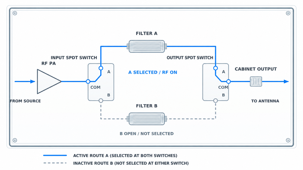
A single filtered channel does not establish the result for every C-UAS operating mode. In a system with selectable bands or multiple RF routes, record which PA, filter, switch position, and output connector were active for each condition covered by the acceptance plan. The same physical cabinet can have different spectral paths as its configuration changes.
Simultaneous-channel operation also requires care. Results from independently driven channels do not necessarily describe intermodulation or other combined-path effects when several channels operate together. The integrator should decide which combinations the system must support and which existing component results remain applicable. If the path identity or filter state cannot be reconstructed from the record, do not use that record to approve the combined condition.
Finally, a conducted result at the cabinet output does not by itself establish the result at the antenna feed point or prove that protected communications remain usable at the installed site. The required feeder, load, antenna, and system boundaries must be verified as specified. The deeper task of C-UAS protected-band coexistence has its own operating and acceptance criteria. Keep that responsibility with the system team instead of attaching an unverified site claim to a PA or filter data sheet.
7. Create a Harmonic Responsibility and Evidence Matrix
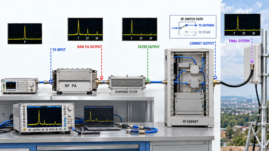
The handoff record separates the requirement owner, hardware provider, and acceptance authority for each measured boundary. The entries below are an RFQ and engineering-review template, not results for a tested RF SKYPOWER unit or a completed C-UAS installation. Replace each “To define” entry with the names, limits, and references agreed for the actual project.
Harmonic Responsibility and Evidence Matrix
| Stage / Reference Plane | Delivered Boundary | Requirement / Limits Owner | Hardware / Integration Owner | Evidence and Test Condition | Acceptance / Open-Item Owner |
|---|---|---|---|---|---|
| Source / driver output at the specified PA input | Input signal and source-path condition | To define: input spectral requirements | To define: source or driver provider | Source baseline, waveform, corrected input levels, frequencies and test settings | To define: PA-input interface reviewer |
| Raw PA output connector | Bare PA module without downstream external filtering | To define: module-level harmonic specification | To define: PA supplier | PA output spectrum under defined Actual Pin, load, RF state, temperature, and frequency-specific corrections | To define: module acceptance reviewer |
| PA plus filter assembly output | Delivered PA and specified filter as one tested combination | To define: filtered-assembly limits and fundamental reference | To define: supplier of the included filter and assembly | PA/filtered-output results, filter identity and state, passband loss, harmonic rejection, power and load conditions | To define: assembly acceptance reviewer |
| Cabinet or selected filtered output | Installed RF switching, filter route, and cabinet output port | To define: cabinet or per-route limits | To define: cabinet and RF-path integrator | Active route map, filter state, required channel combinations, corrected spectrum at cabinet reference plane | To define: system integration reviewer |
| Installed RF system / agreed final boundary | Specified feeder, antenna interface, and applicable system configuration | To define: project requirements and applicable approval authority | To define: system integrator and installation parties | Evidence at the agreed conducted or other prescribed system boundary under required operating modes | To define: final system acceptance authority |
The parties may coincide. For example, a supplier delivering an integrated PA and filter may own the assembly’s output verification, while another project may source those items separately. Do not delete the downstream acceptance requirement merely because two rows share an organization.
For every required row, the reviewer should attach the actual limit, evidence reference, configuration and responsible sign-off. An open item means that the evidence or responsibility is still undefined; it is not a supplier failure or an assumed pass. Where the project requires unit-level evidence, the specified results should be linked to the applicable unit and serial number. Sampling, design qualification, and system-level tests retain their own agreed scope. The broader C-UAS RF PA delivery evidence checklist covers shipment release beyond this harmonic-filtering responsibility decision.
RFQ: What Must Be Agreed Before the Harmonic Boundary Is Frozen?
Before quoting or approving a PA/filter arrangement, ask the relevant supplier and system integrator to confirm the same written interface and acceptance plan. The RFQ should specify:
- Operating signal: Required fundamental frequencies or bands, waveform, occupied bandwidth, duty cycle, and individual or simultaneous modes.
- Harmonic requirement: Each covered order or frequency, the limit in dBm or dBc (or the approved waveform-specific method), and the fundamental reference where needed.
- Reference-plane drawing: PA input, raw PA output, filter output, cabinet port, and final applicable system point, with the delivered boundary identified.
- Filter responsibility: Internal or external supply, filter identity and revision, active switching state, assembly and integration owner, and change approval.
- Power and interface conditions: Actual PA input drive, required useful output at the relevant plane, filter insertion loss, stopband response, average/peak power, load, return loss, and thermal state.
- Measurement evidence: Frequency-specific sampling corrections, analyzer method and relevant settings, raw and corrected results, and conditions required for direct comparison.
- Evidence scope: Which results require a design qualification, sample, batch, configuration, or delivered-unit/S/N-linked report under the agreed plan.
- Acceptance authority: Who reviews each row of the matrix, what happens if a result is outside the defined limit, and which missing information prevents sign-off.
The RFQ need not assume that one party supplies the entire chain. It does need to make sure a filtered-system limit cannot be assigned to a bare PA vendor without an agreed basis, and that no one describes a filter’s component specification as final system compliance.
With those conditions defined, RF power amplifier module options can serve as a starting point for product-family discovery. That page is not evidence that a particular module, external filter, or complete installation meets the project’s harmonic limits.
Conclusion: Put the Limit Where It Will Be Accepted
Harmonic-filtering responsibility belongs at the reference plane and delivered hardware boundary specified by the accepted requirement. The party supplying a bare PA should provide evidence for its agreed unfiltered PA-port conditions; whoever delivers a filtered assembly must support that assembly’s specified output; and the designated system authority must verify the final installed requirement within its own scope. Those assignments can differ by contract and configuration.
A filtered-output pass does not erase a separate bare-PA obligation, and a PA-port result does not prove downstream or site compliance. Both judgments require the actual frequencies, waveform, load, filter state, corrections, operating condition, limit, and reference plane.
Before assigning a failure or authorizing acceptance, complete the responsibility matrix, resolve missing owners or limits, and request measurements tied to the correct interface. For an RF SKYPOWER PA-related engineering discussion, provide the required operating bands, drive and output conditions, filter arrangement, interface drawing, harmonic limits, and the specific module-level evidence expected. Product fit and any system-level acceptance remain subject to the project’s own engineering review and verification.