










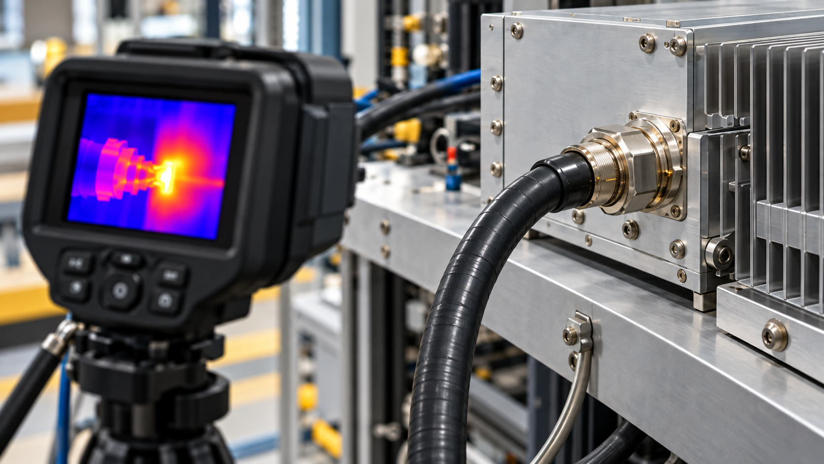
RF connector overheating can result from contact resistance, dielectric loss, impedance mismatch, or heat conducted from nearby equipment. These mechanisms can coexist. A hot connector therefore needs two kinds of evidence: a credible temperature pattern and RF measurements taken under comparable operating conditions.
The useful question is which explanation the available evidence supports, what remains unproven, and which measurement can narrow the diagnosis.
1. Why a Hot RF Connector Is Not a Root-Cause Diagnosis
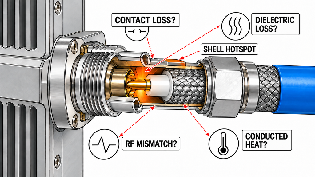
A deteriorated mating contact can increase resistive loss and generate heat near the connection. The same deterioration may also disturb RF amplifier impedance matching by introducing a local connector discontinuity that changes reflection and current distribution.
Other mechanisms can produce similar surface temperatures:
- Dielectric loss within a connector or adjacent RF component.
- Elevated local RF current associated with a standing-wave pattern.
- Heat conducted from the PA enclosure, mounting hardware, or neighboring components.
- Environmental heating combined with normal RF losses.
The location of a shell hotspot can help prioritize these possibilities, but the external surface temperature is not a direct measurement of the internal contact temperature.
Contact loss and mismatch should remain separate, potentially overlapping hypotheses until the electrical evidence and a controlled retest support a narrower conclusion.
2. Which Conditions Must Match Before Comparing Connector Heat?
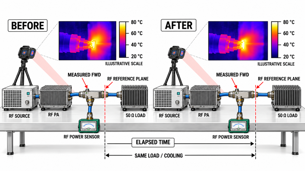
A connector running cooler after a cable replacement does not establish that the replacement corrected a contact defect. The comparison must first establish what else changed.
Identify both mating halves and their installation position. Then compare the operating frequency, actual forward power, waveform, duty cycle, load, cooling conditions, and initial thermal state.
Use measured forward power rather than the PA’s commanded setting. Record whether the reported power is CW, average, peak, or another defined measurement, including the instrument’s measurement or averaging basis. Protection-related power reduction can otherwise make a hot connector appear to improve.
The RF measurement configuration matters equally. Record the coupler location, instrument identity, correction factors, calibration status, and reference plane. Thermal observations must have identifiable timestamps and elapsed operating times so that they can be matched to the relevant RF readings.
A useful comparison also accounts for measurement uncertainty. A small temperature or RF difference that falls within the measurement system’s uncertainty or repeatability cannot establish which mechanism changed.
Classify the result before interpreting it:
- Comparable: The variables relevant to the suspected mechanism are controlled, and the observed difference is meaningful.
- Partially comparable: Some evidence remains useful, but the uncontrolled variables limit the conclusion.
- Not comparable yet: Missing power, reference-plane, timing, or thermal-state information prevents a defensible comparison.
A laboratory load baseline and an installed antenna path may impose different RF conditions. The comparison of controlled-load testing and installed RF chains helps define that distinction when the operating path changes.
3. How to Measure Connector Temperature Rise Without IR Errors
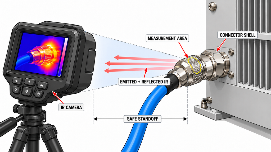
Thermal inspection should establish where the temperature rise occurs and how it develops over time.
Observe the connector shell alongside a nearby cable section, the PA output region, and an appropriate environmental reference. Record the initial temperatures, operating duration, measurement location, and temperature trend. Localized heating has a different diagnostic meaning from an entire mounting structure warming at a similar rate.
Infrared measurements of reflective metal surfaces require particular care. Apparent temperature depends on emissivity, reflected temperature, viewing angle, and the measurement setup. A bright region in a thermal image may be influenced by reflected radiation rather than the connector’s actual surface temperature.
Optical resolution is another constraint. Verify that the camera is correctly focused and that the suspected hotspot occupies the effective measurement area required by the specific camera and lens at the working distance. If the target is too small, surrounding cooler pixels may dilute its apparent temperature.
An unresolved or poorly focused hotspot can be reported as a limited thermal observation, but its displayed maximum should not be treated as a reliable quantitative temperature.
Where a reference surface or marker is appropriate, qualified personnel should prepare it only under approved RF-off and de-energized conditions, after confirming that it will not affect connector ratings, cooling, or safety.
Finally, allow for thermal response time. An internal heating change can precede a measurable rise on the outer shell. An apparently normal shell during a short observation window does not rule out developing internal heating.
Never approach an energized high-power RF assembly merely to obtain a closer thermal image. If the available safe distance cannot provide valid quantitative resolution, record that limitation.
4. Which RF Measurements Separate Loss From Reflection?
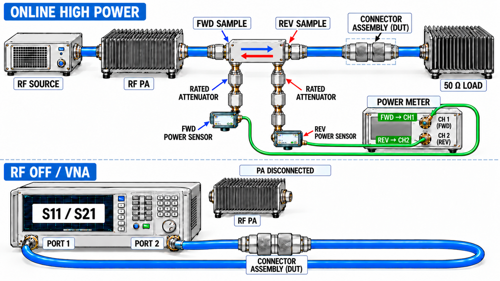
Forward power, reflected power, and transmission loss describe different aspects of an RF path. None independently identifies the source of connector heating.
For an RF amplifier VSWR test conducted under approved high-power conditions, compare actual FWD and REV readings at a defined, calibrated reference plane. A normalized reflected-power ratio is generally more informative than absolute REV alone because REV may fall when the PA reduces forward power.
Coupler directivity, correction factors, and measurement uncertainty still affect the result. Measurements taken from different reference planes cannot be compared as though they describe the same electrical location.
PA-side FWD/REV data can support an estimate of RF power amplifier output VSWR at that measurement plane when the readings and correction factors are valid. They do not separately quantify the power dissipated in a particular downstream connector.
After RF output has been safely stopped, appropriately calibrated small-signal measurements can provide additional evidence:
- S11 characterizes reflection at its calibrated reference plane.
- S21 characterizes forward transmission across the measured path, including the combined effects of mismatch and dissipative loss.
A change in S21 does not isolate contact resistance or determine how much power became heat inside one connector.
Measurement state must also be preserved. A low-power S-parameter result obtained after shutdown, cooling, or disassembly cannot be treated as a simultaneous measurement of the earlier high-power thermal condition. A VNA must not be connected to an active high-power RF output.
One less obvious possibility deserves attention: loss along a path can attenuate the signal reaching a downstream discontinuity and the reflected signal returning upstream. Consequently, lower PA-side REV does not necessarily mean that downstream matching has improved.
When a reflected-power alarm is the primary symptom rather than localized heating, the diagnosis of reflected-power alarms after installation addresses the wider RF path.
5. How to Combine the Thermal Map and RF Evidence
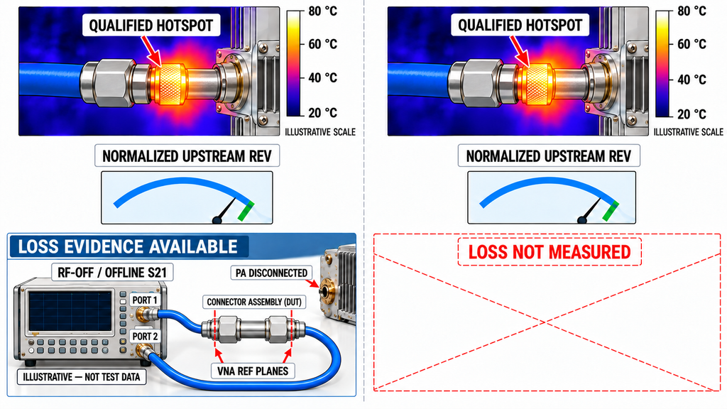
Combine thermal observations with RF data only after checking their measurement validity, operating conditions, and time relationship.
The following matrix distinguishes six evidence situations. They are diagnostic patterns, not RF SKYPOWER field-test results or confirmed failure mechanisms.
| Thermal evidence | RF electrical evidence | Consider first | What it cannot prove | Next verification |
|---|---|---|---|---|
| 1. Qualified local hotspot during a documented online window | Independent path-loss evidence has worsened across identified measurement planes; normalized upstream REV is stable or lower. State whether the loss evidence came from a comparable online measurement or a separately timed offline S21 test. | Path-related dissipation, possibly alongside mismatch. | That the measured loss occurs entirely inside the hot connector, or that an offline result represents online heat dissipation. | Verify the loss measurement scope, assembly state, and uncertainty; then isolate the relevant path section under approved conditions. |
| 2. Qualified local hotspot during the same online RF window | Corrected, normalized REV increases at the same reference plane under comparable forward power. | A mismatch contribution, potentially combined with local loss. | That the hot connector is the location or sole cause of the mismatch. | Use an approved reference-plane or interface isolation test to determine whether the reflection change follows that interface. |
| 3. No resolved local shell hotspot under optically qualified observation | Normalized REV increases during the recorded online window. | An RF mismatch or reflection change; internal heating may not yet have reached the shell. | That the fault involves only mismatch or that internal heating is absent. | Review the safe temperature-time trend, observation duration, and thermal response lag before drawing a thermal conclusion. |
| 4. Broad warming of nearby structure, without a qualified focal hotspot | Corrected RF readings remain stable under comparable operating conditions. | Conducted or environmental heating. | That the connector is defect-free or operates within its approved thermal limit. | Compare temperature trends across the PA housing, connector, cable, and environmental reference. |
| 5. Qualified local hotspot during online operation | Upstream normalized REV is stable or lower, but only PA-side FWD/REV exists; no independent path-loss evidence is available. | An unresolved local heating mechanism. Path loss masking downstream reflection remains possible. | That contact loss has been measured or that the downstream path is correctly matched. | Obtain an independent loss or downstream reflection measurement with defined reference planes and a clearly recorded measurement state. |
| 6. Thermal and RF evidence are not comparable | Time windows, power, thermal state, optical validity, corrections, or reference planes are inconsistent or unknown. | A measurement or comparison problem. | Any reliable ranking of contact loss, mismatch, or external heating. | Re-establish the missing measurement conditions before repeating the comparison. |
Swipe horizontally to compare all five evidence fields →
The distinction between Rows 1 and 5 is the availability of independent path-loss evidence. A stable or falling upstream reflection reading alone does not establish that loss is masking a downstream reflection.
If the assembly is remated, moved, or replaced before an offline S21 measurement, that result characterizes the modified connection state. It cannot independently verify the loss present during the earlier hot-state observation.
The matrix should leave the engineer with a prioritized hypothesis, the strongest remaining uncertainty, and one relevant next measurement—not a declaration that the internal failure point has already been identified.
6. How to Isolate the Mating Interface With a Controlled Retest
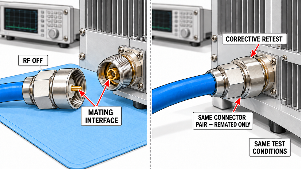
A retest can strengthen fault attribution, but its conclusion must match the scope of the intervention.
Replacing the complete cable assembly: If heating or RF behavior improves, the original assembly or reconstructed connection path is implicated. The result does not identify which connector half, termination, or internal contact caused the change.
Remating the same connector pair: A repeatable change supports suspicion involving mating condition, contact repeatability, or mechanical state. Remating itself changes the interface, so improvement does not establish a particular internal defect.
Isolating an approved, specific interface: If changing only that interface repeatedly changes the anomaly under comparable conditions, suspicion becomes more localized. Even then, the result does not independently distinguish center-contact damage, outer-conductor contact, plating deterioration, or dielectric loss.
All interventions require approved RF shutdown, de-energization where applicable, cooling, and inspection procedures. Never touch, retighten, move, or replace a connector while high-power RF is present. Replacement components must have suitable ratings for the actual application.
When evidence implicates a termination, the diagnosis of RF connector crimping problems covers that specific inspection task. If an adapter is involved, RF adapter path errors require their own controlled assessment.
7. When Should the Test Stop or the Connector Be Replaced?
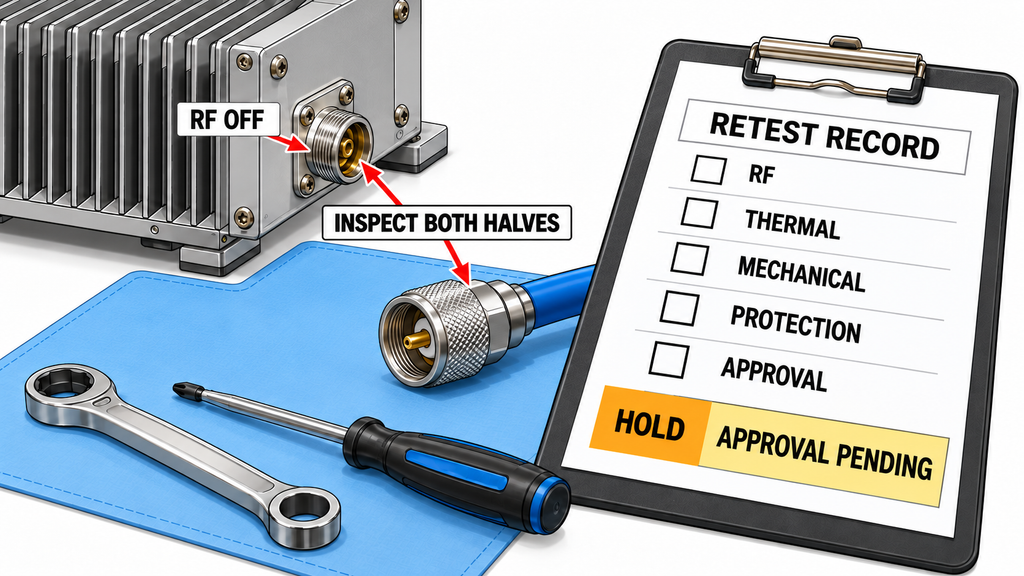
Stop criteria and acceptance limits must come from the applicable connector documentation, equipment requirements, and approved project test procedure. There is no defensible universal temperature threshold for every N-type connector. A PA’s internal overtemperature setting is not an external connector temperature limit.
Five different outcomes should be distinguished:
- Stop immediately when there is uncontrolled temperature rise, visible damage, exceeded operating limits, an abnormal protection event, or another condition requiring shutdown under the approved safety procedure.
- Isolate for inspection when connector identity, mating condition, measurement validity, or the cause of an unsafe indication remains unresolved.
- Replace an unsuitable or damaged component when inspection or applicable documentation establishes that continued use is not permitted. Examine both mating halves before selecting the corrective action.
- Perform a corrective retest after an approved intervention, using the specified frequency, actual power, waveform, duty cycle, load, cooling conditions, and thermal duration.
- Restore operation only after the required RF, thermal, mechanical, and protection-related acceptance conditions are documented as satisfied by the responsible authority.
In an RF amplifier test report, a lower connector temperature after remating should be recorded as evidence of a changed condition, not as standalone evidence for release.
The following blank record keeps online high-power observations separate from RF-off inspection and offline S-parameter results.
| Measurement stage and required fields | Record | |
|---|---|---|
| Pre-run — Identification: | PA model and S/N where applicable; connector location; identities of both mating halves and associated assembly. | __________ |
| Pre-run — Approved conditions: | Required frequencies, power and duty limits, connector ratings, load/reflection limits, applicable acceptance criteria, and their document sources. | __________ |
| Pre-run — Setup: | Date/time, initial thermal state, ambient and cooling conditions, coupler and instrument IDs, calibration status, correction basis, and RF reference planes. | __________ |
| Online high-power — Operating window: | Timestamp, elapsed operating time, frequency, actual forward-power value and measurement definition, waveform, duty cycle, load, and cooling state. | __________ |
| Online high-power — RF evidence: | FWD/REV raw and corrected values with units, corrections, measurement basis, normalized reflection or VSWR where applicable, reference plane, and protection status. | __________ |
| Online high-power — Thermal evidence: | Connector and adjacent reference points, temperatures or qualified anomaly observations, temperature-rise trend and time window; emissivity, reflected temperature, distance, angle, lens, focus, target size/resolution, and measurement validity. | __________ |
| After RF shutdown — Condition: | Shutdown timestamp, elapsed time since RF-off, thermal state, protection history, and inspection findings for both mating halves. | __________ |
| After RF shutdown — Offline RF: | S11/S21 where available, measurement time, measured path, calibrated planes, temperature state, and any assembly changes before measurement. | __________ |
| Intervention — Controlled variable: | Date/time, authorization, replaced or remated part, both mating identities, component ratings, and all other changes to the path. | __________ |
| Corrective retest — Comparison: | Repeated operating conditions, actual power, thermal duration, RF and thermal observations, protection behavior, and uncertainty or comparability limitations. | __________ |
| Decision — Attribution: | Current hypothesis, contradictory evidence, maximum supported fault location, unresolved conditions, and next verification. | __________ |
| Decision — Disposition: | Stop, isolate, replace, corrective retest, or restore operation; applicable limits, supporting record, responsible reviewer, and approval date. | __________ |
Swipe horizontally to review the complete staged record →
The record supports a decision only to the extent that its measurements are valid and the applicable limits are known. It is not a substitute for the project’s formal acceptance procedure.
If the investigation shows that the PA output interface, operating power, or connector configuration must be reconsidered, the RF SKYPOWER RF power amplifier module range provides a product-family reference for engineering review. Suitability of any specific configuration still requires project-specific verification.
Wideband RF PA Modules
Select a frequency band to compare standard 30 W–200 W models and open the applicable English PDF datasheets.
30–512 MHz · 5 standard models
| Power | Model / PDF | Psat min. / typ. | Current typ. / max. | Dimensions | RF input / output | Control |
|---|---|---|---|---|---|---|
| 30 W | 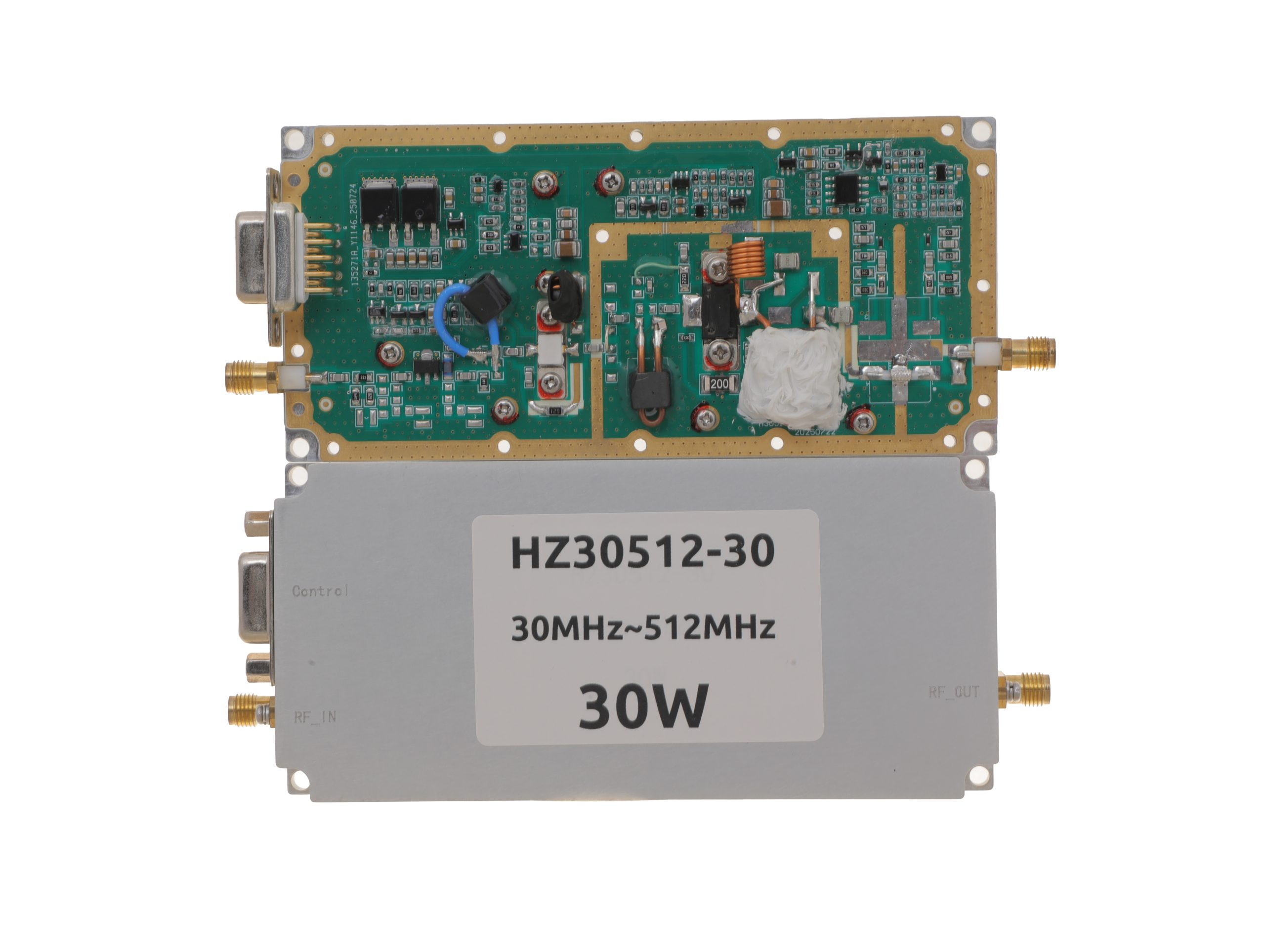 HZ30512-30NA1Open English PDF ↗ | 25 / 30 W | 3.2 / 4 A | 125 × 59 × 21.5 mmWeight: 0.5 kg | SMA-KFD46 / SMA-KFD46 | 9-pin D-Sub |
| 50 W | 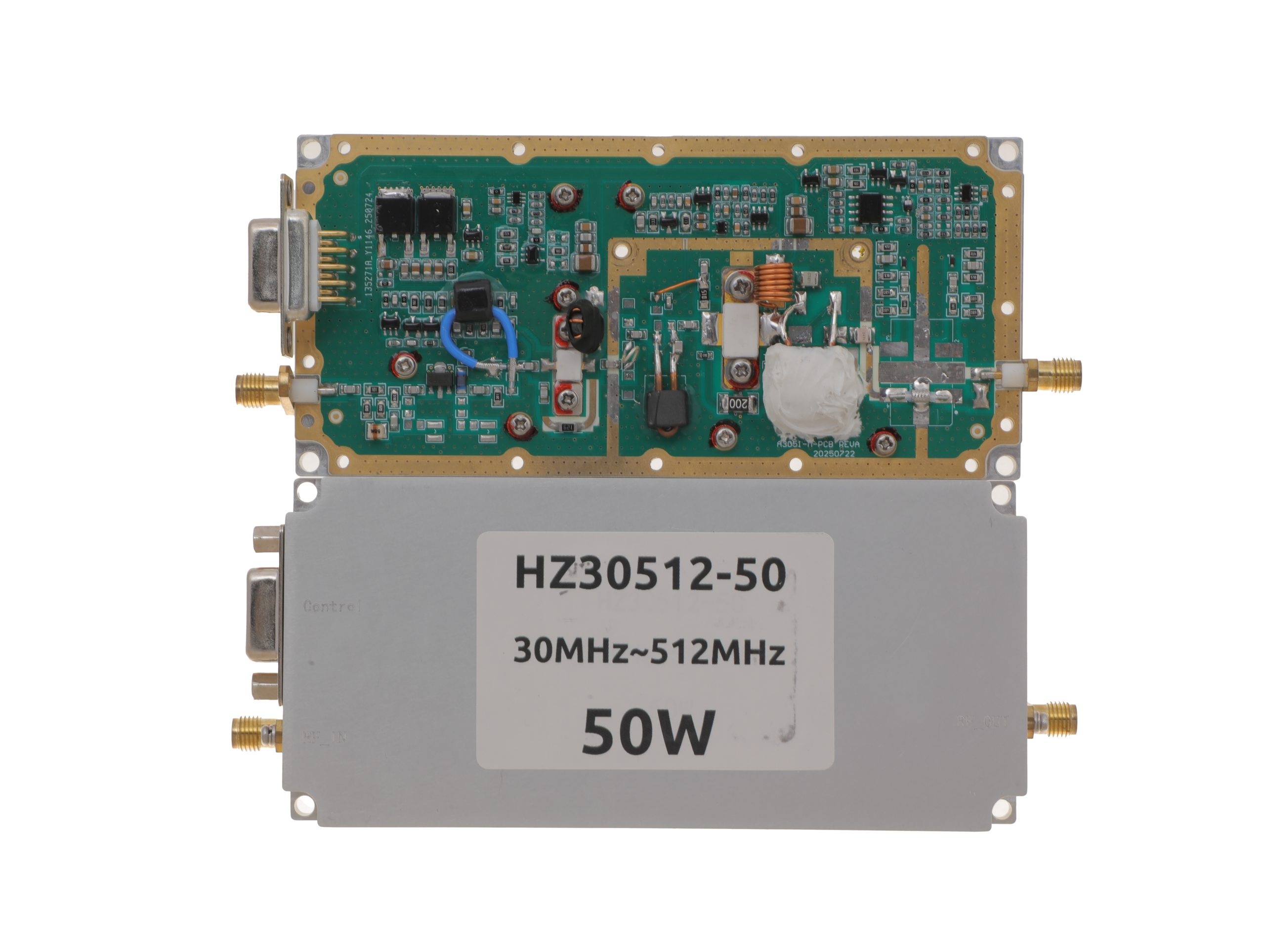 HZ30512-50NA1Open English PDF ↗ | 40 / 50 W | 7.2 / 9 A | 125 × 59 × 21.5 mmWeight: 0.5 kg | SMA-KFD46 / SMA-KFD46 | 9-pin D-Sub |
| 100 W | 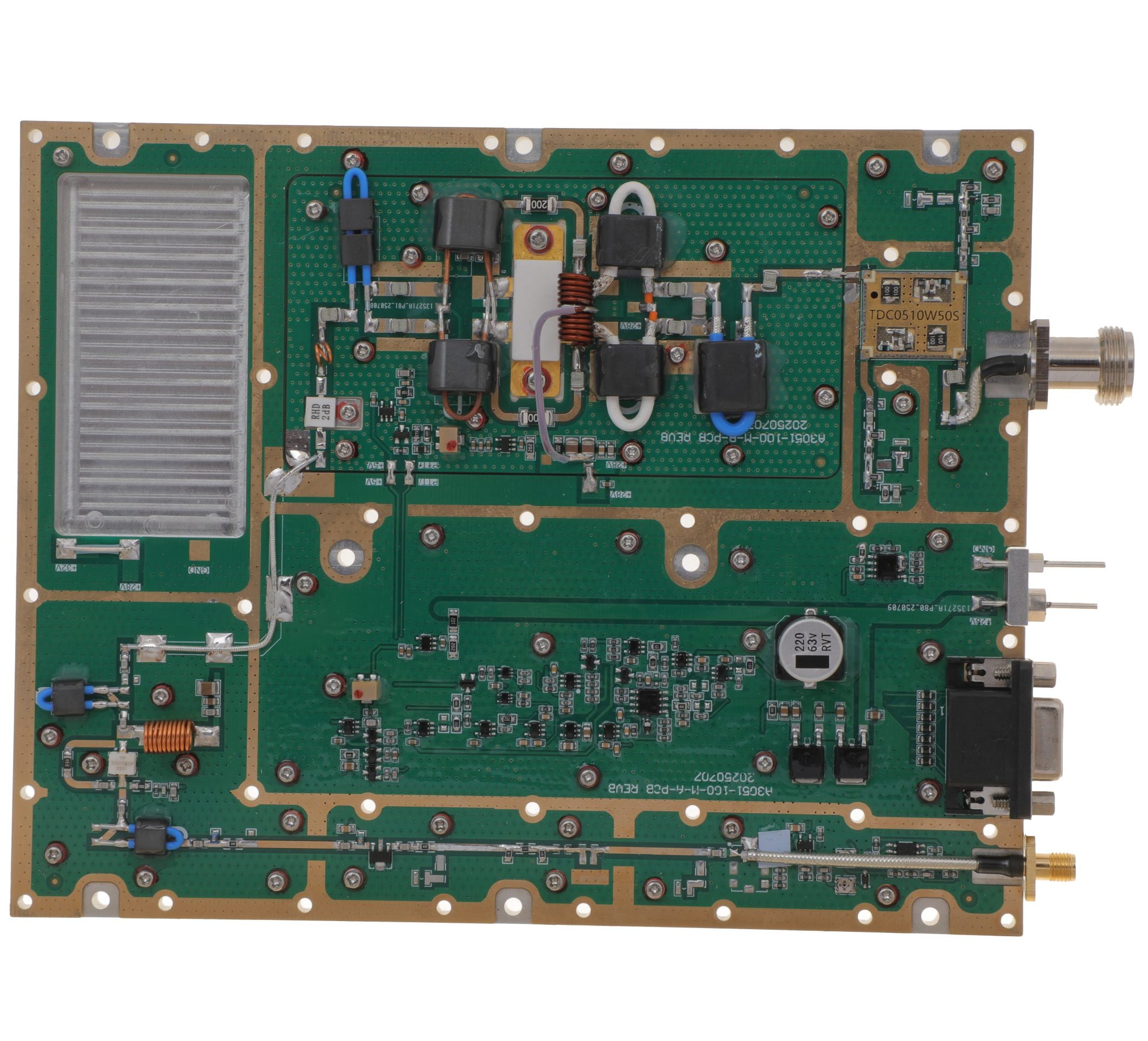 HZ30512-100NA1Open English PDF ↗ | 80 / 100 W | 14.5 / 18 A | 160 × 120 × 25 mmWeight: 1.4 kg | SMA-F / N-F | 15-pin D-Sub |
| 150 W | 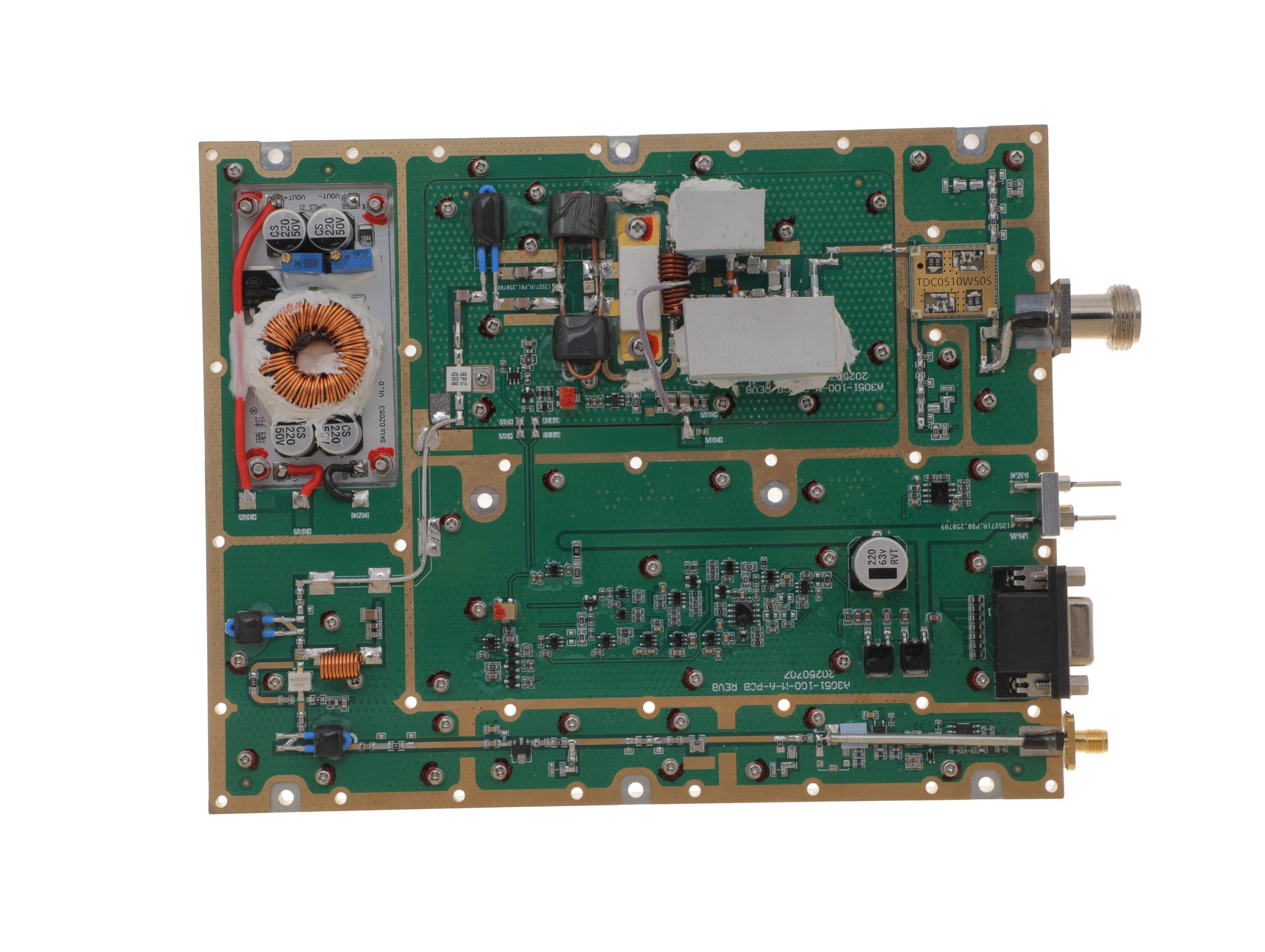 HZ30512-150NA1Open English PDF ↗ | 120 / 150 W | 16 / 20 A | 200 × 158 × 25 mmWeight: 1.4 kg | SMA-F / N-F | 15-pin D-Sub |
| 200 W | 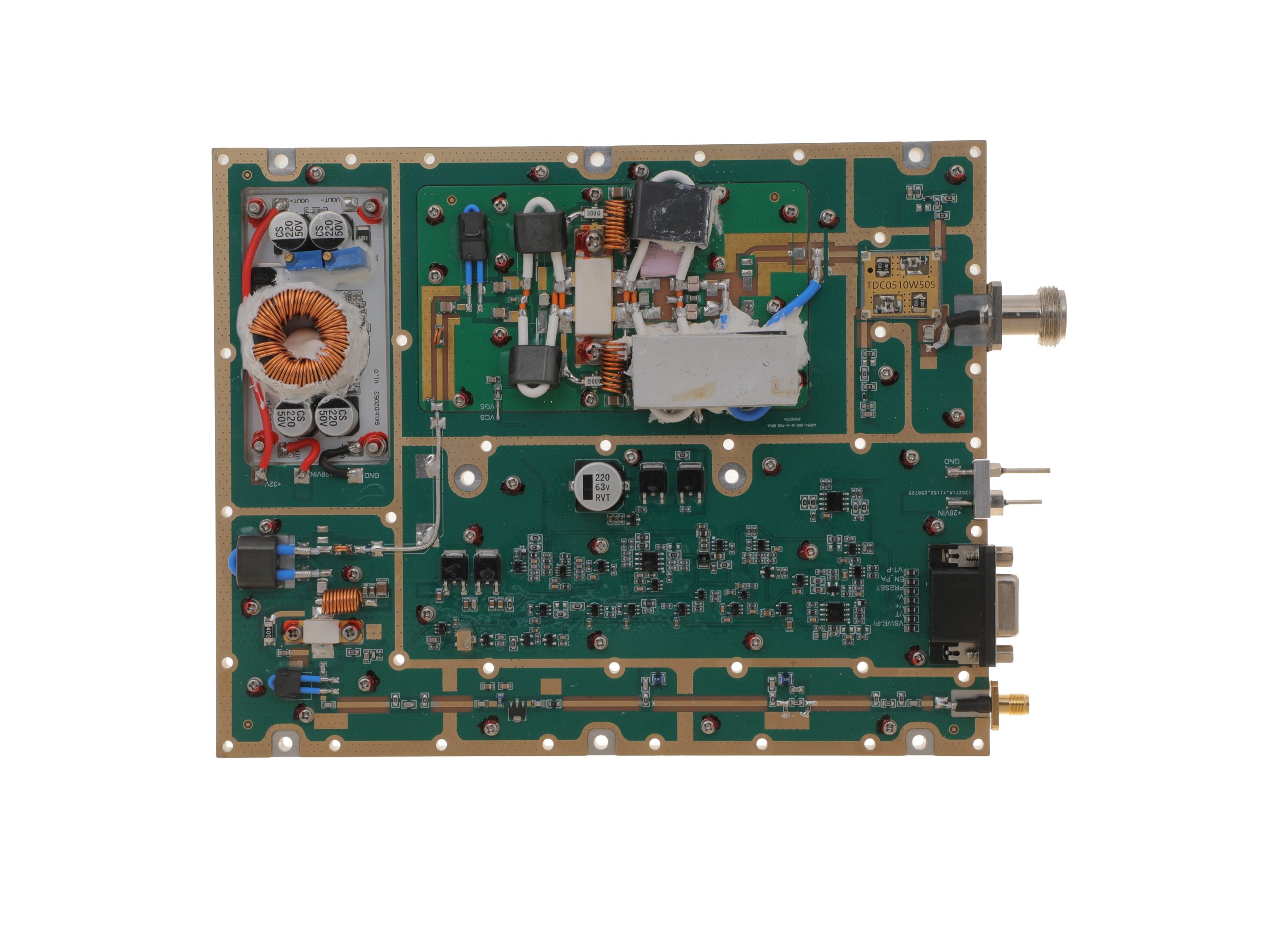 HZ30512-200NA1Open English PDF ↗ | 160 / 200 W | 29 / 36 A | 200 × 158 × 25 mmWeight: 1.4 kg | SMA-F / N-F | 15-pin D-Sub |
300–1200 MHz · 5 standard models
| Power | Model / PDF | Psat min. / typ. | Current typ. / max. | Dimensions | RF input / output | Control |
|---|---|---|---|---|---|---|
| 30 W | 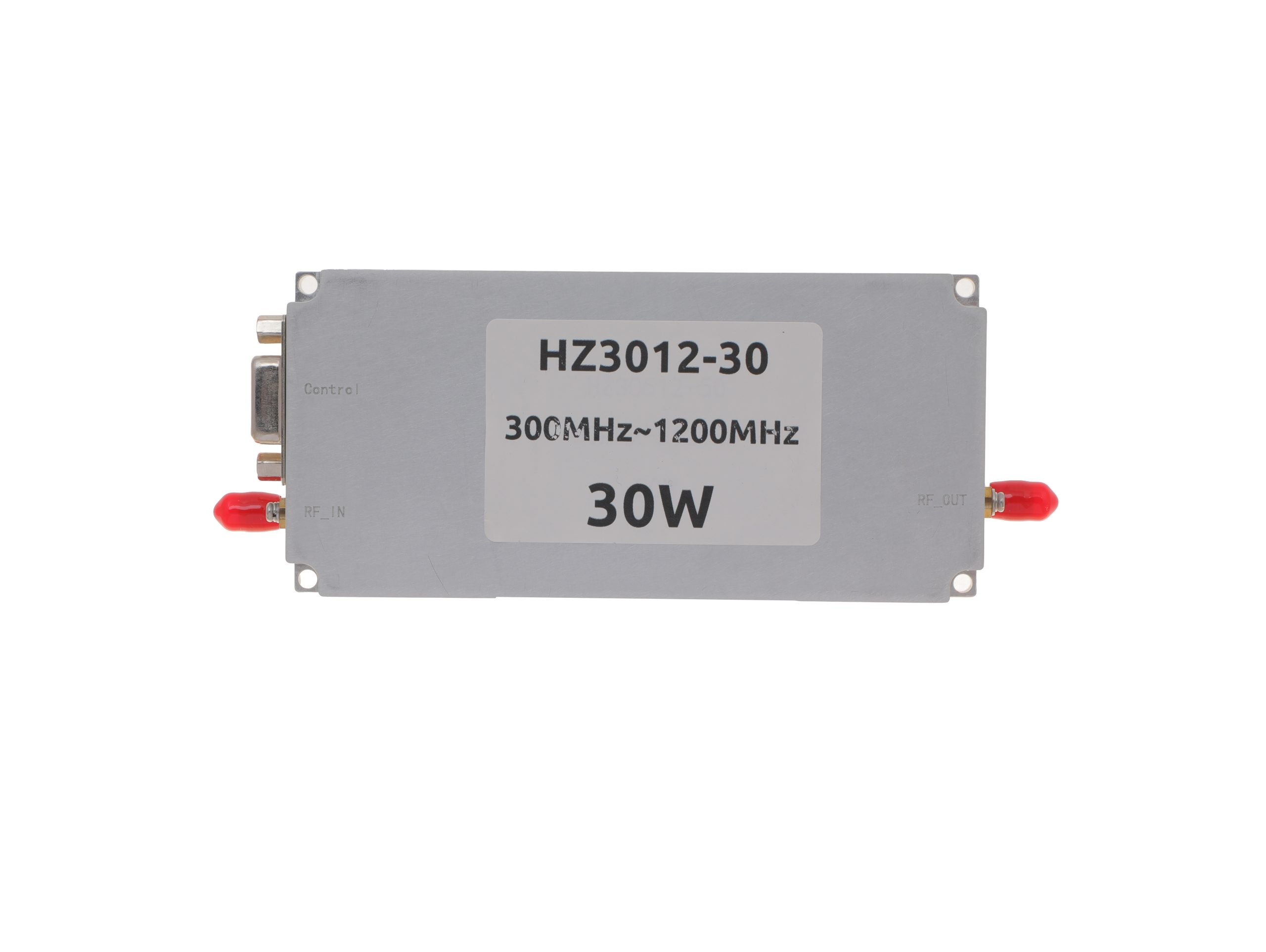 HZ3001200-30Open English PDF ↗ | 25 / 30 W | 2.4 / 3 A | 125 × 59 × 21.5 mm | SMA-KFD46 / SMA-KFD46 | 9-pin D-Sub |
| 50 W | 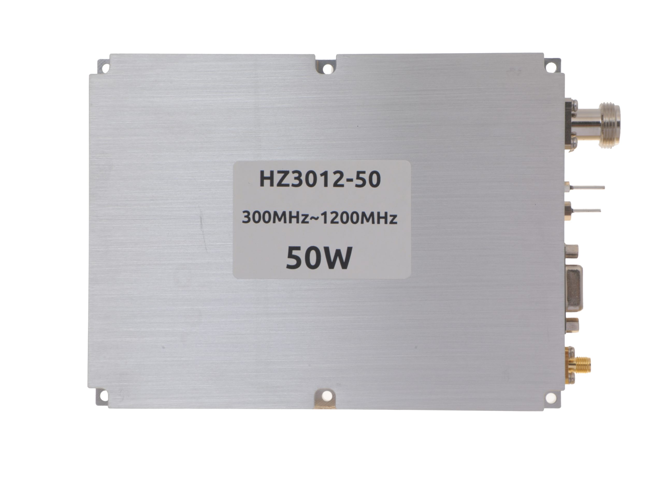 HZ3001200-50Open English PDF ↗ | 40 / 50 W | 5.6 / 7 A | 125 × 59 × 21.5 mm | SMA-KFD46 / SMA-KFD46 | 9-pin D-Sub |
| 100 W | 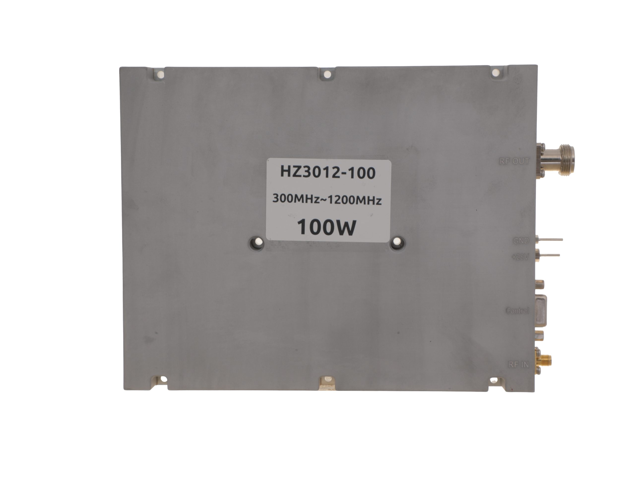 HZ3001200-100Open English PDF ↗ | 80 / 100 W | 11.5 / 14 A | 200 × 158 × 25 mm | SMA-F / N-F | 15-pin D-Sub |
| 150 W | 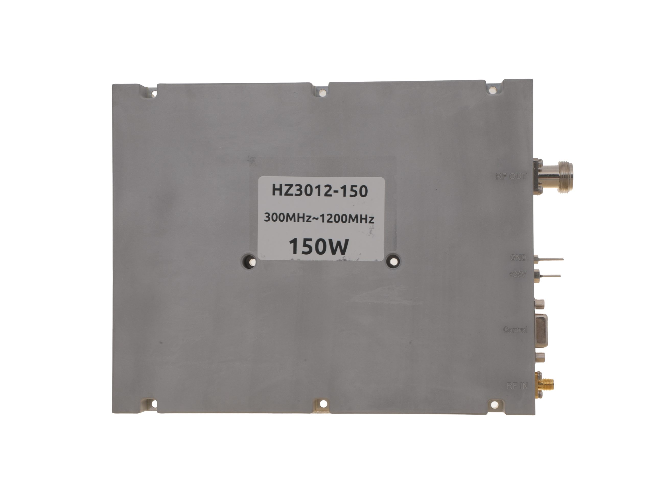 HZ3001200-150Open English PDF ↗ | 120 / 150 W | 18 / 22 A | 200 × 158 × 25 mm | SMA-F / N-F | 15-pin D-Sub |
| 200 W | 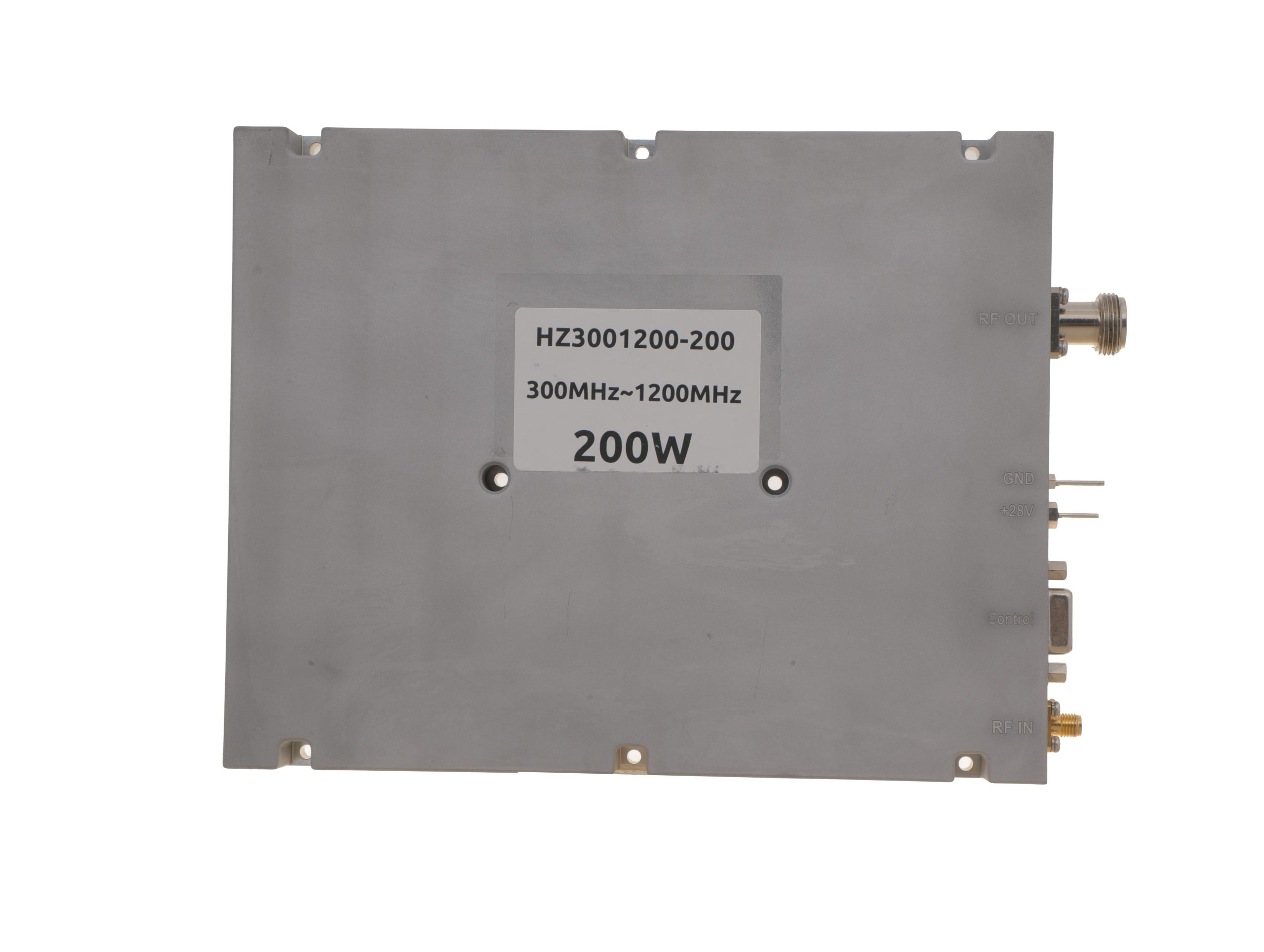 HZ3001200-200Open English PDF ↗ | 160 / 200 W | 24 / 29 A | 200 × 158 × 25 mm | SMA-F / N-F | 15-pin D-Sub |
300–1700 MHz · 5 standard models
| Power | Model / PDF | Psat min. / typ. | Current typ. / max. | Dimensions | RF input / output | Control |
|---|---|---|---|---|---|---|
| 30 W | 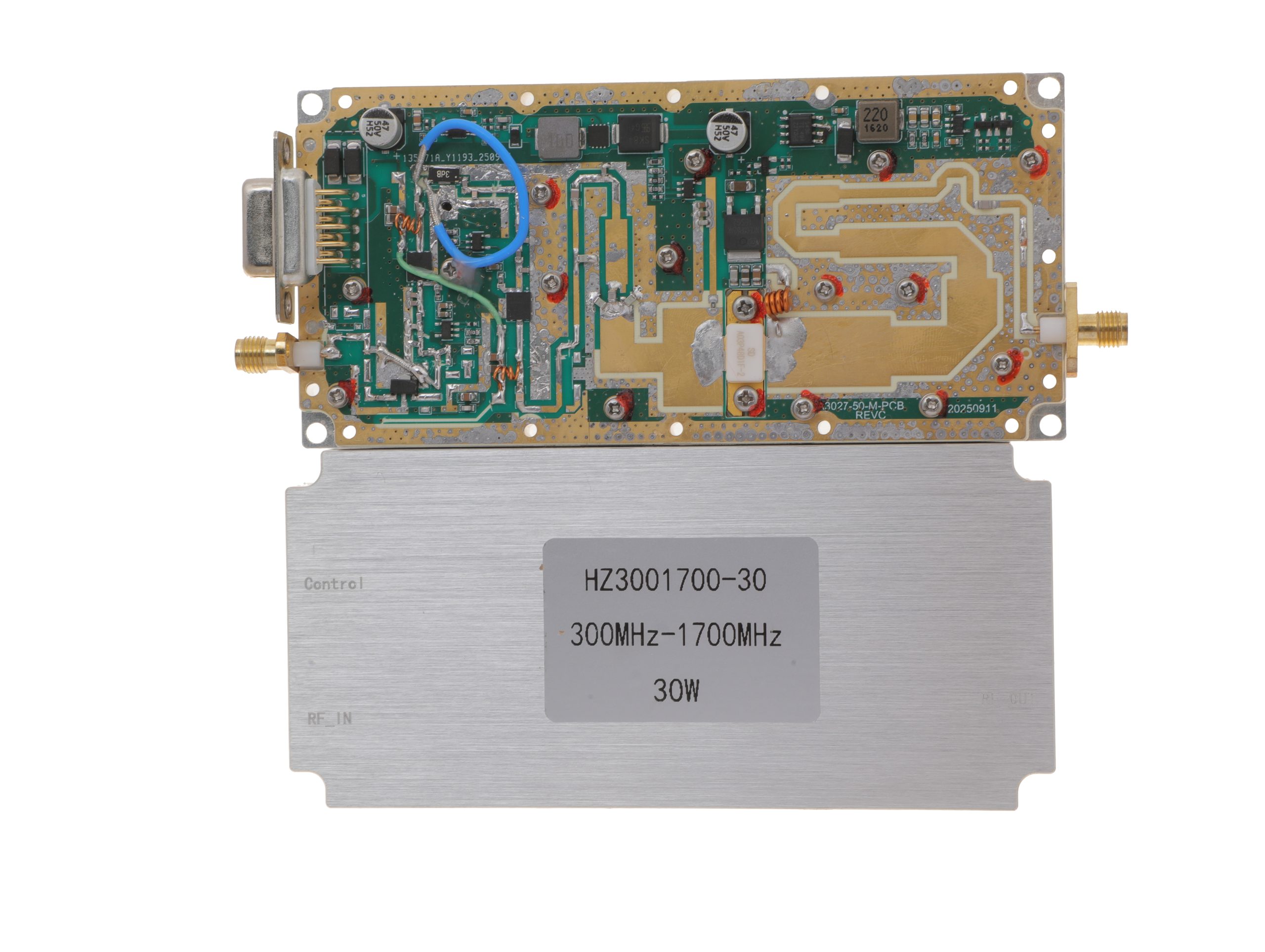 HZ3001700-30Open English PDF ↗ | 25 / 30 W | 2.4 / 3 A | 125 × 59 × 21.5 mm | SMA-KFD46 / SMA-KFD46 | 9-pin D-Sub |
| 50 W | 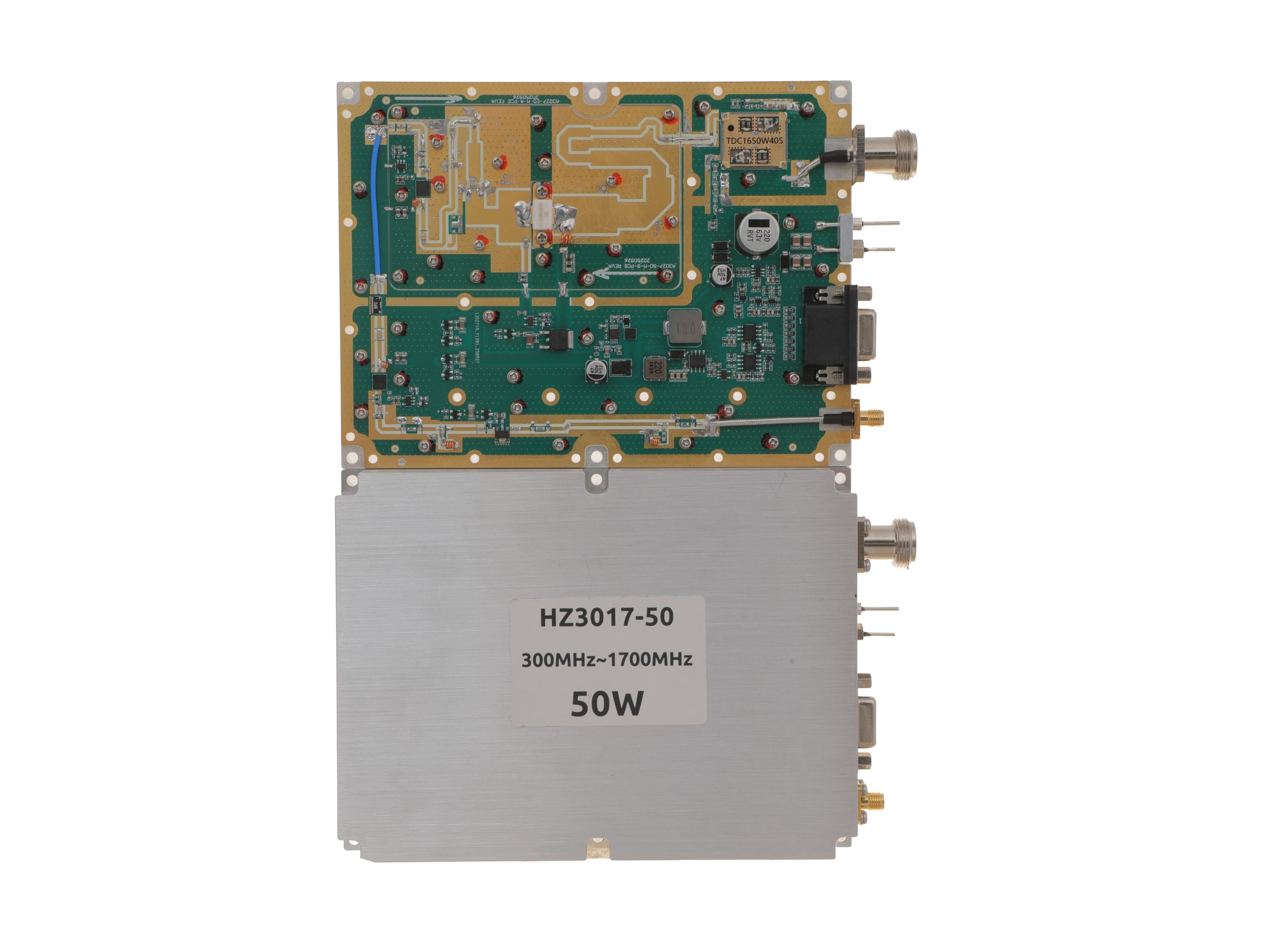 HZ3001700-50Open English PDF ↗ | 40 / 50 W | 5.6 / 7 A | 160 × 120 × 25 mm | SMA-F / N-F | 15-pin D-Sub |
| 100 W | 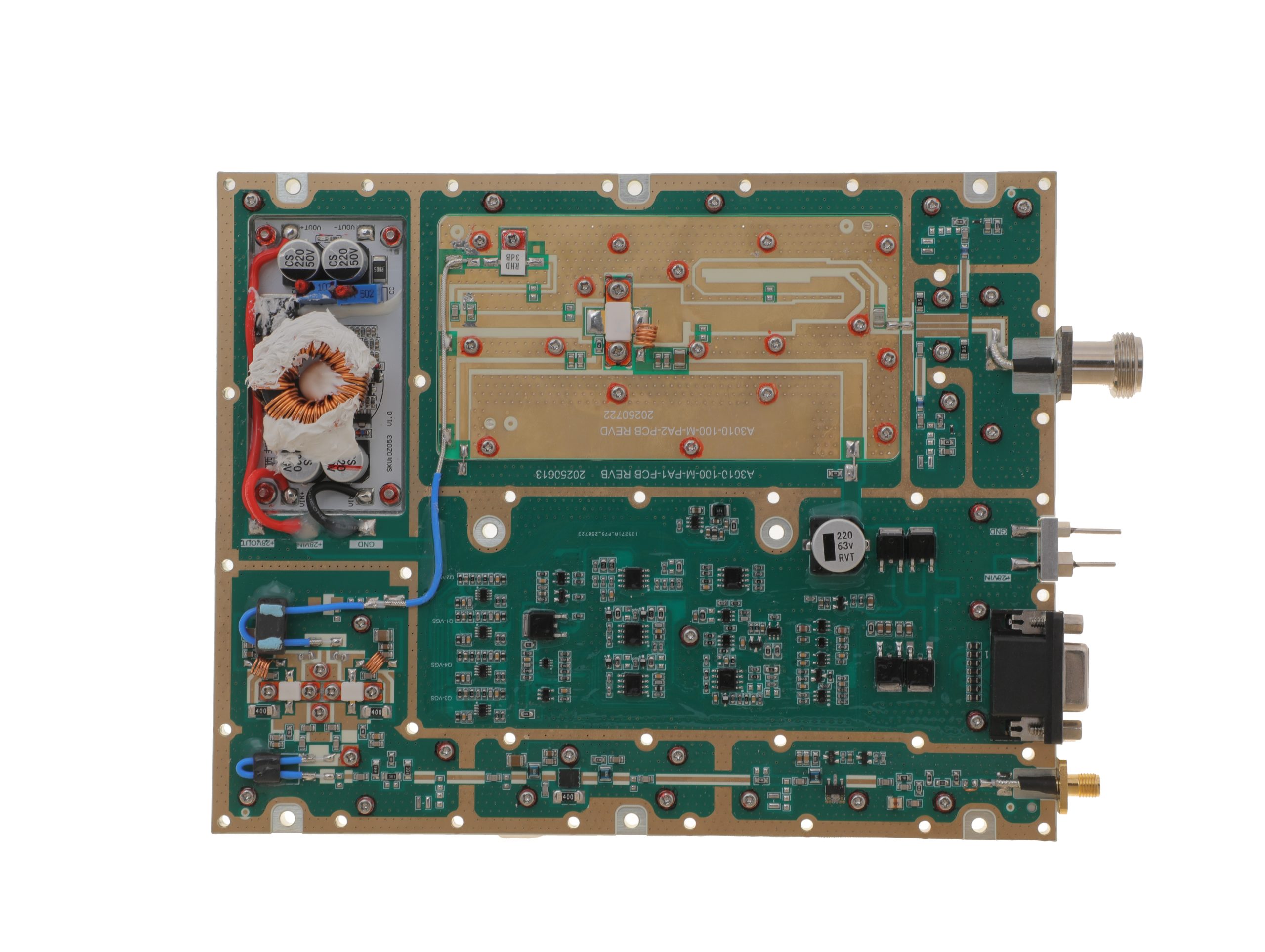 HZ3001700-100Open English PDF ↗ | 80 / 100 W | 11.5 / 14 A | 200 × 158 × 25 mm | SMA-F / N-F | 15-pin D-Sub |
| 150 W | 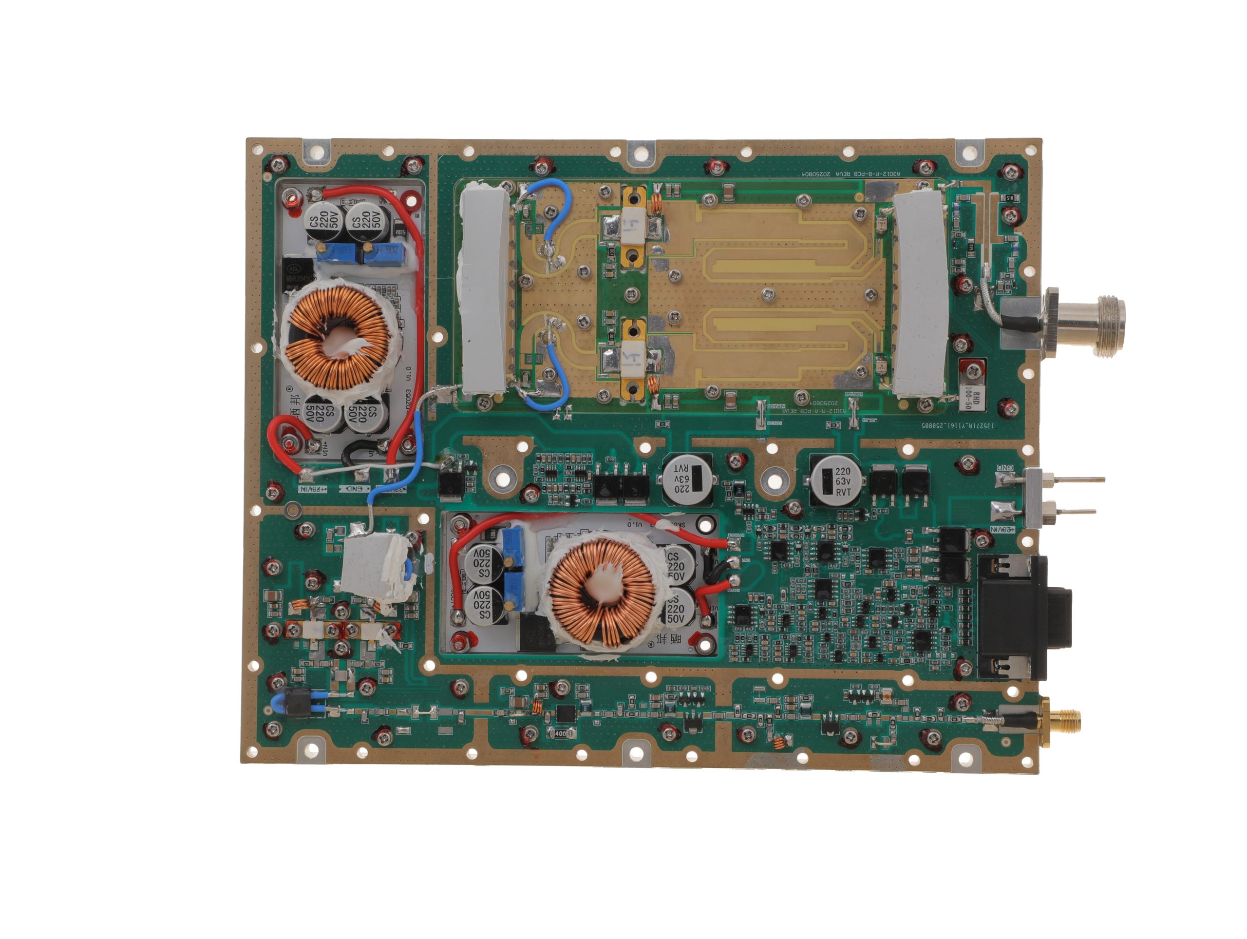 HZ3001700-150Open English PDF ↗ | 120 / 150 W | 18 / 22 A | 200 × 158 × 25 mm | SMA-F / N-F | 15-pin D-Sub |
| 200 W | 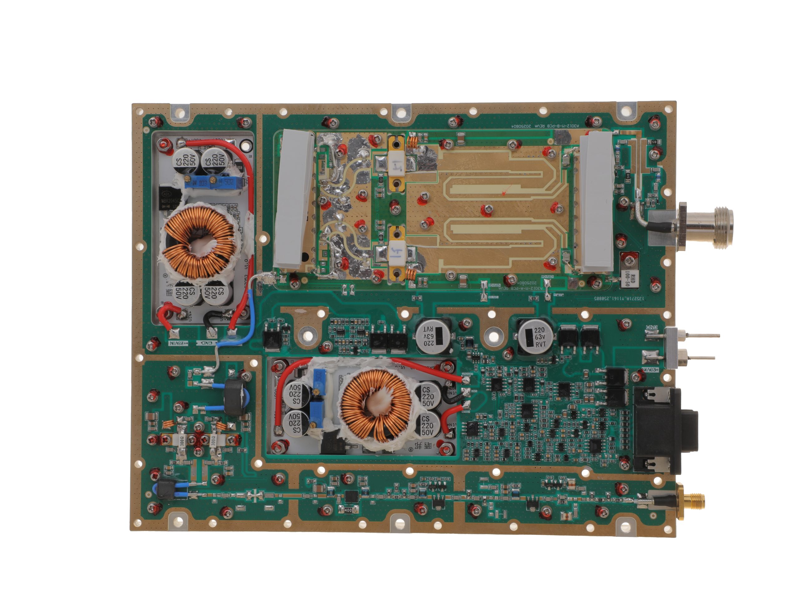 HZ3001700-200Open English PDF ↗ | 158 / 200 W | 24 / 29 A | 200 × 158 × 25 mm | SMA-F / N-F | 15-pin D-Sub |
300–2700 MHz · 5 standard models
| Power | Model / PDF | Psat min. / typ. | Current typ. / max. | Dimensions | RF input / output | Control |
|---|---|---|---|---|---|---|
| 30 W | 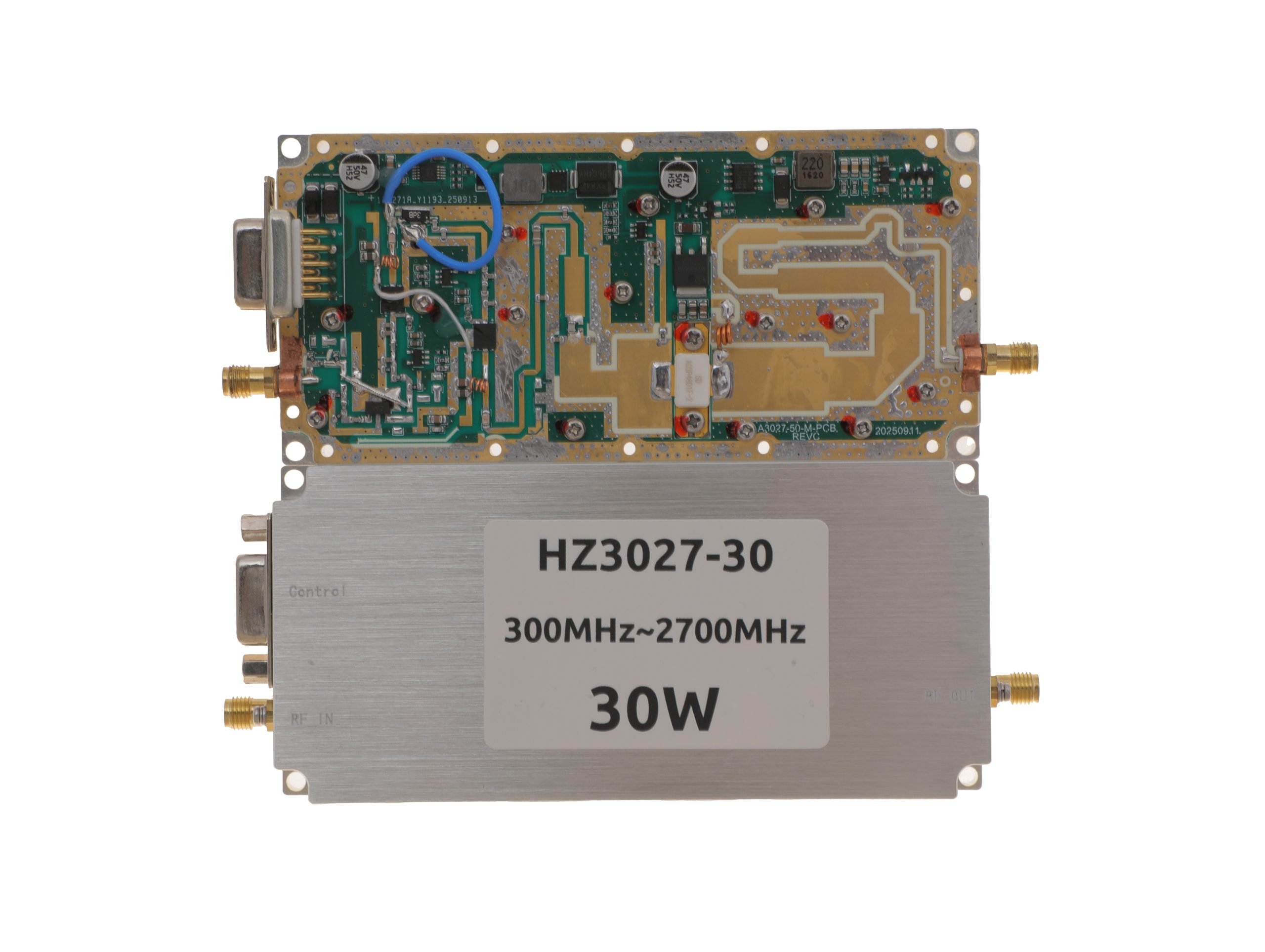 HZ3002700-30NA1Open English PDF ↗ | 25 / 30 W | 3.2 / 4 A | 125 × 59 × 21.5 mm | SMA-KFD46 / SMA-KFD46 | 9-pin D-Sub |
| 50 W | 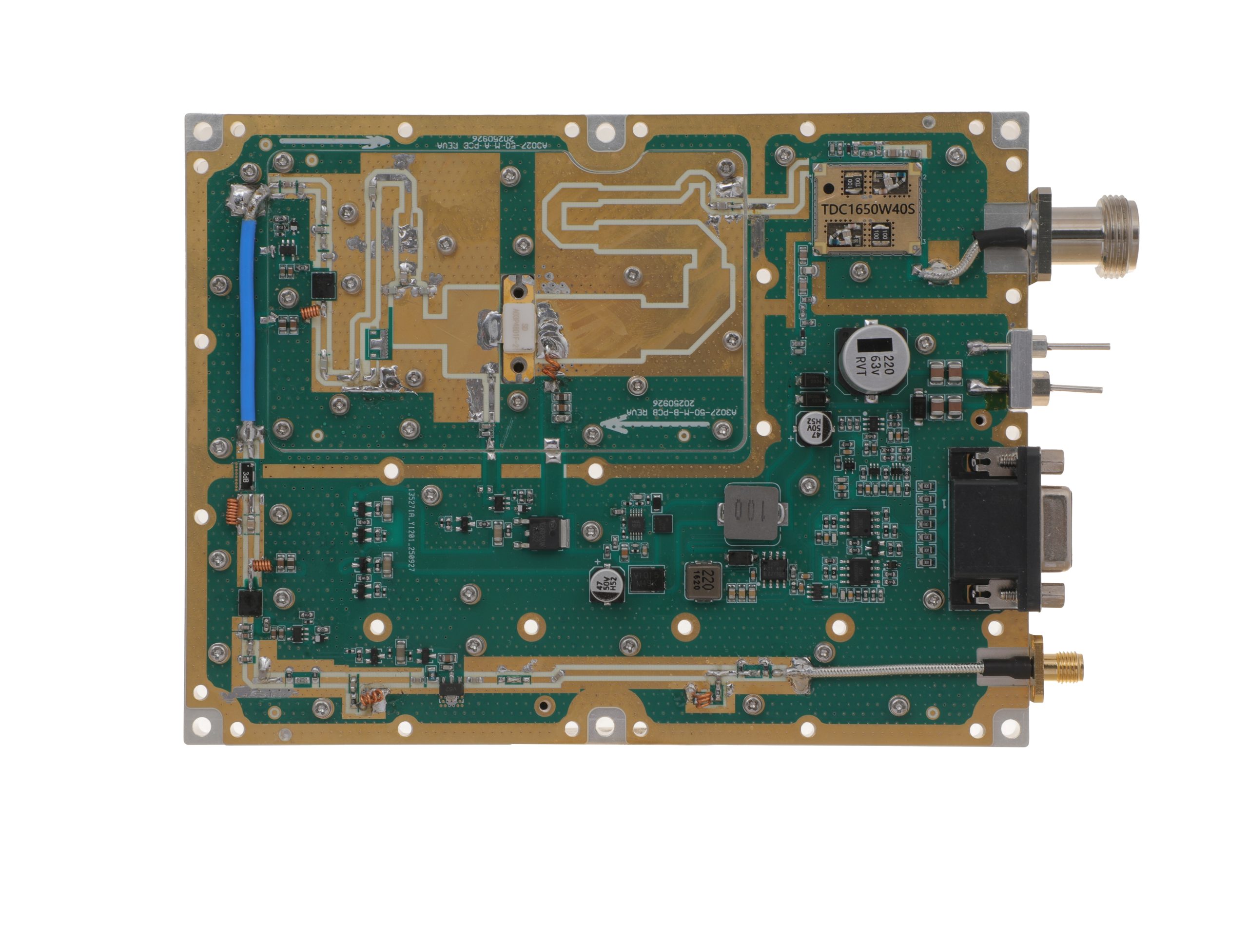 HZ3002700-50NA1Open English PDF ↗ | 40 / 50 W | 7.2 / 9 A | 160 × 120 × 25 mm | SMA-F / N-F | 15-pin D-Sub |
| 100 W | 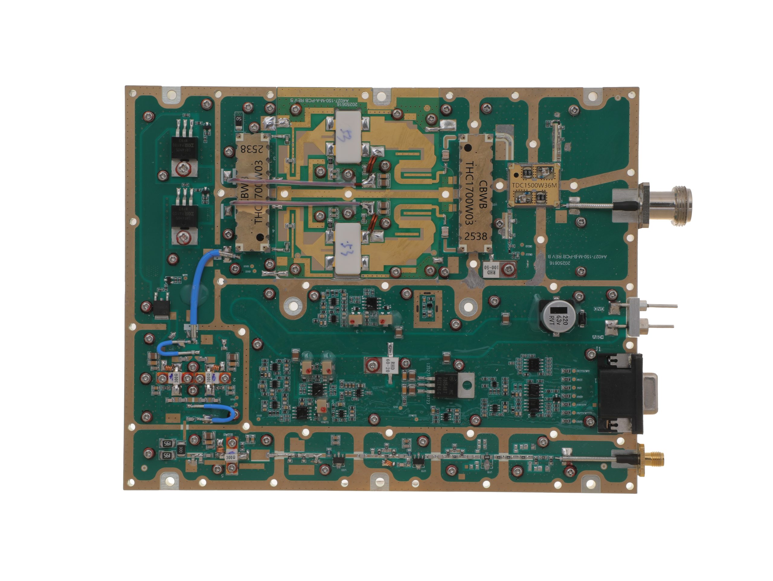 HZ3002700-100NA1Open English PDF ↗ | 80 / 100 W | 14.5 / 18 A | 200 × 158 × 25 mm | SMA-F / N-F | 15-pin D-Sub |
| 150 W | 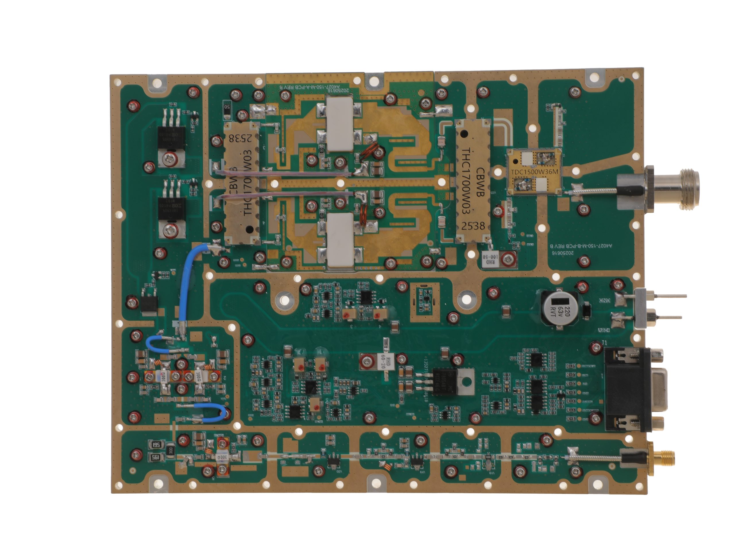 HZ3002700-150NA1Open English PDF ↗ | 120 / 150 W | 16 / 20 A | 200 × 158 × 25 mm | SMA-F / N-F | 15-pin D-Sub |
| 200 W | 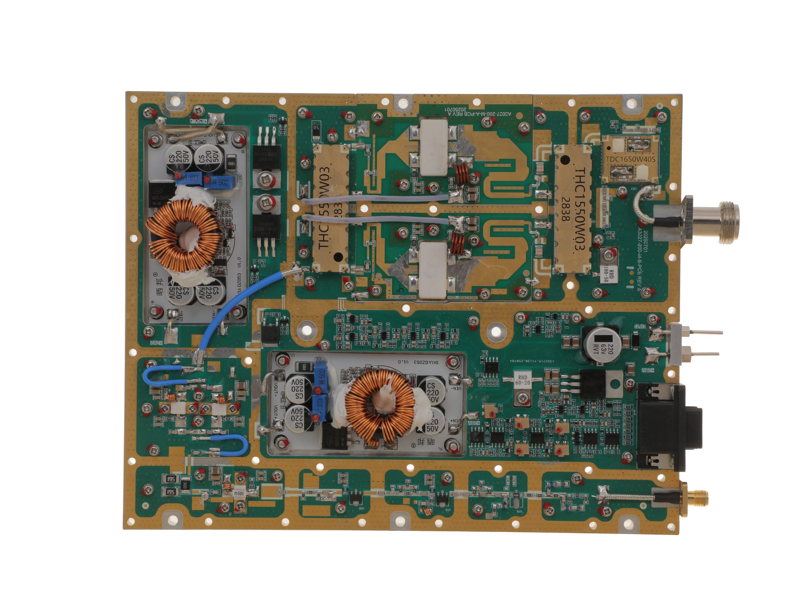 HZ3002700-200NA1Open English PDF ↗ | 160 / 200 W | 29 / 36 A | 200 × 158 × 25 mm | SMA-F / N-F | 15-pin D-Sub |
2000–6000 MHz · 5 standard models
| Power | Model / PDF | Psat min. / typ. | Current typ. / max. | Dimensions | RF input / output | Control |
|---|---|---|---|---|---|---|
| 30 W | 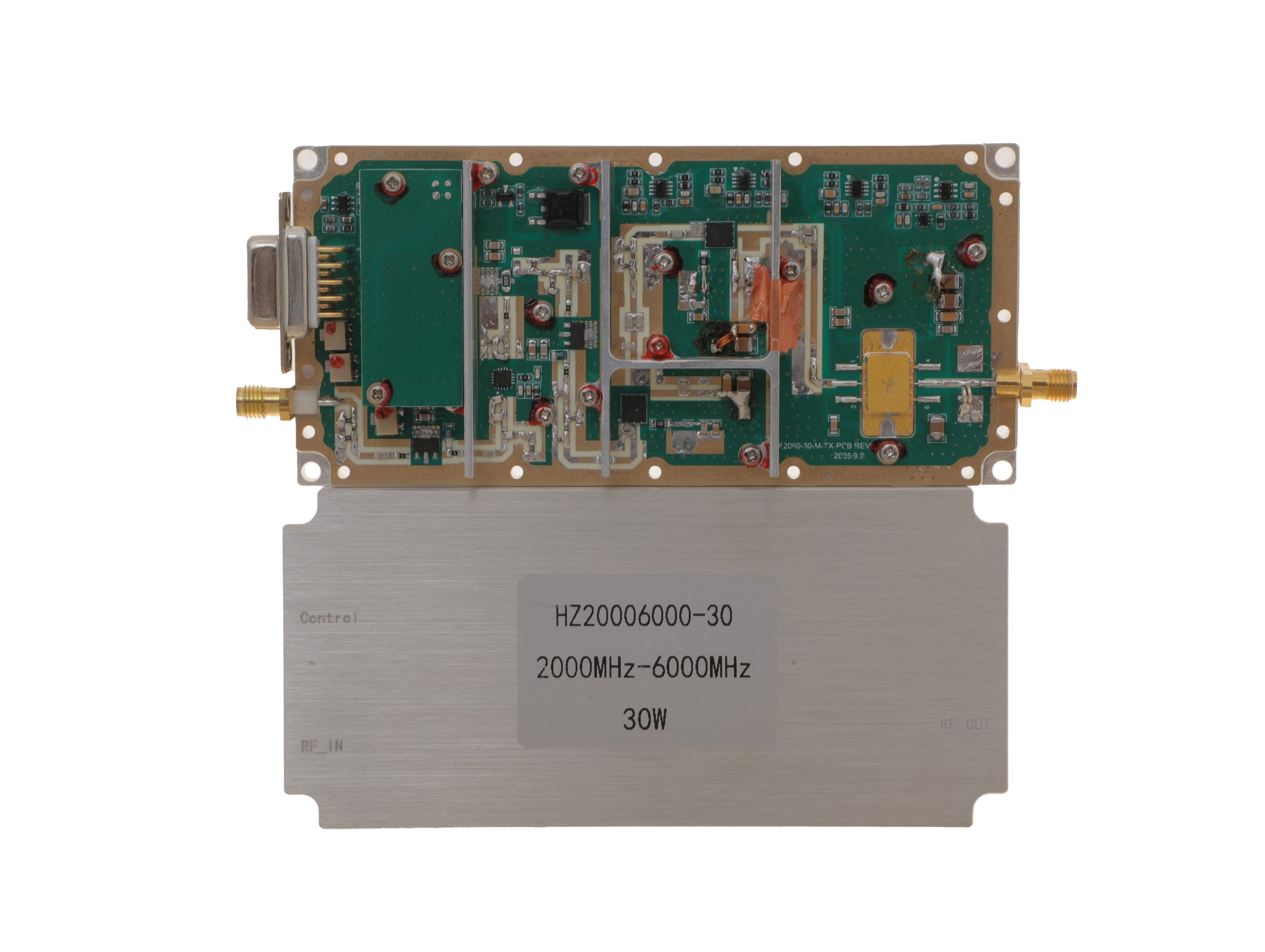 HZ20006000-30NA1Open English PDF ↗ | 25 / 30 W | 3.2 / 4 A | 125 × 59 × 21.5 mm | SMA-KFD46 / SMA-KFD46 | 9-pin D-Sub |
| 50 W | 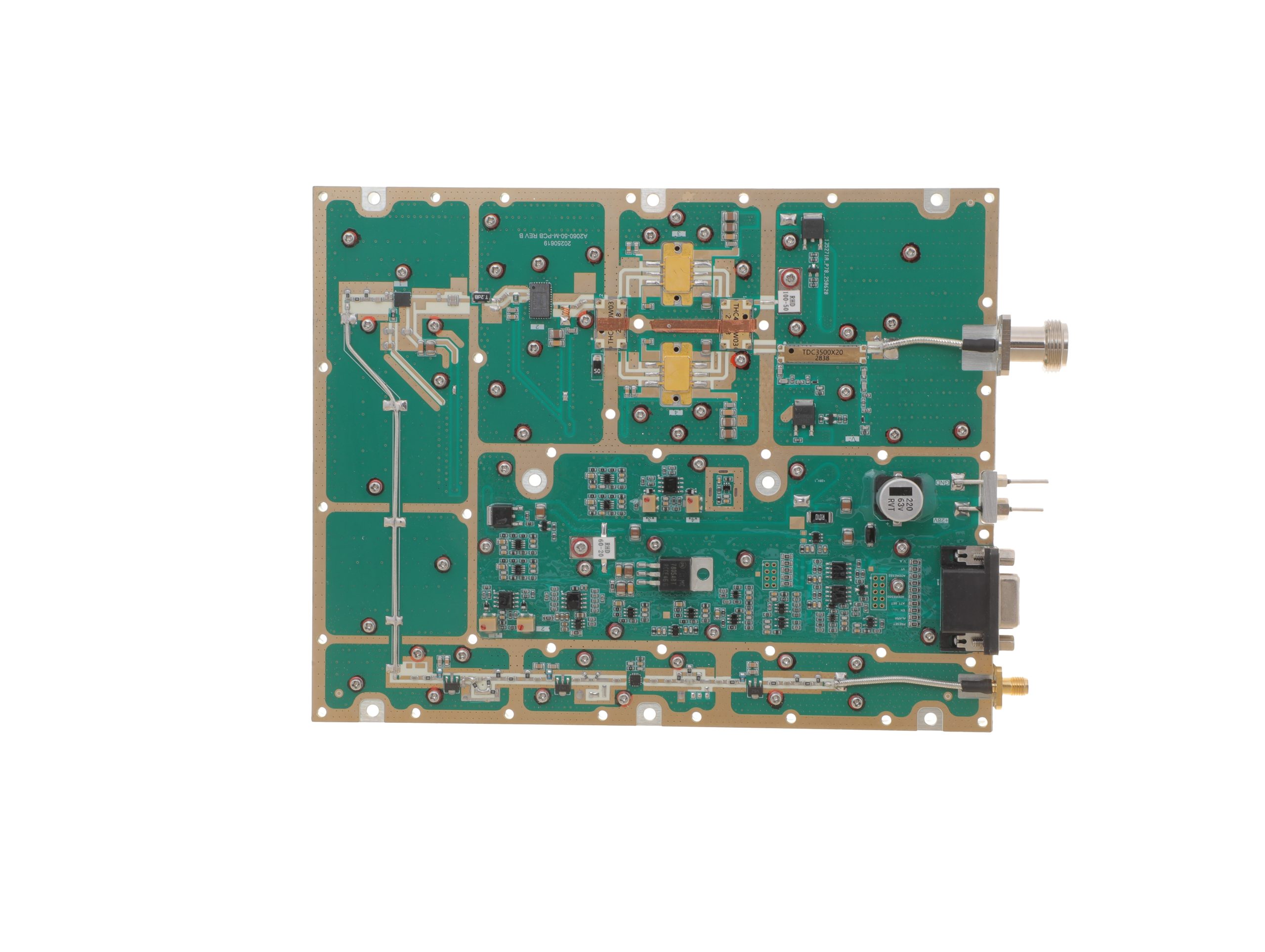 HZ20006000-50NA1Open English PDF ↗ | 40 / 50 W | 10 / 12 A | 200 × 158 × 25 mm | SMA-F / N-F | 15-pin D-Sub |
| 100 W | 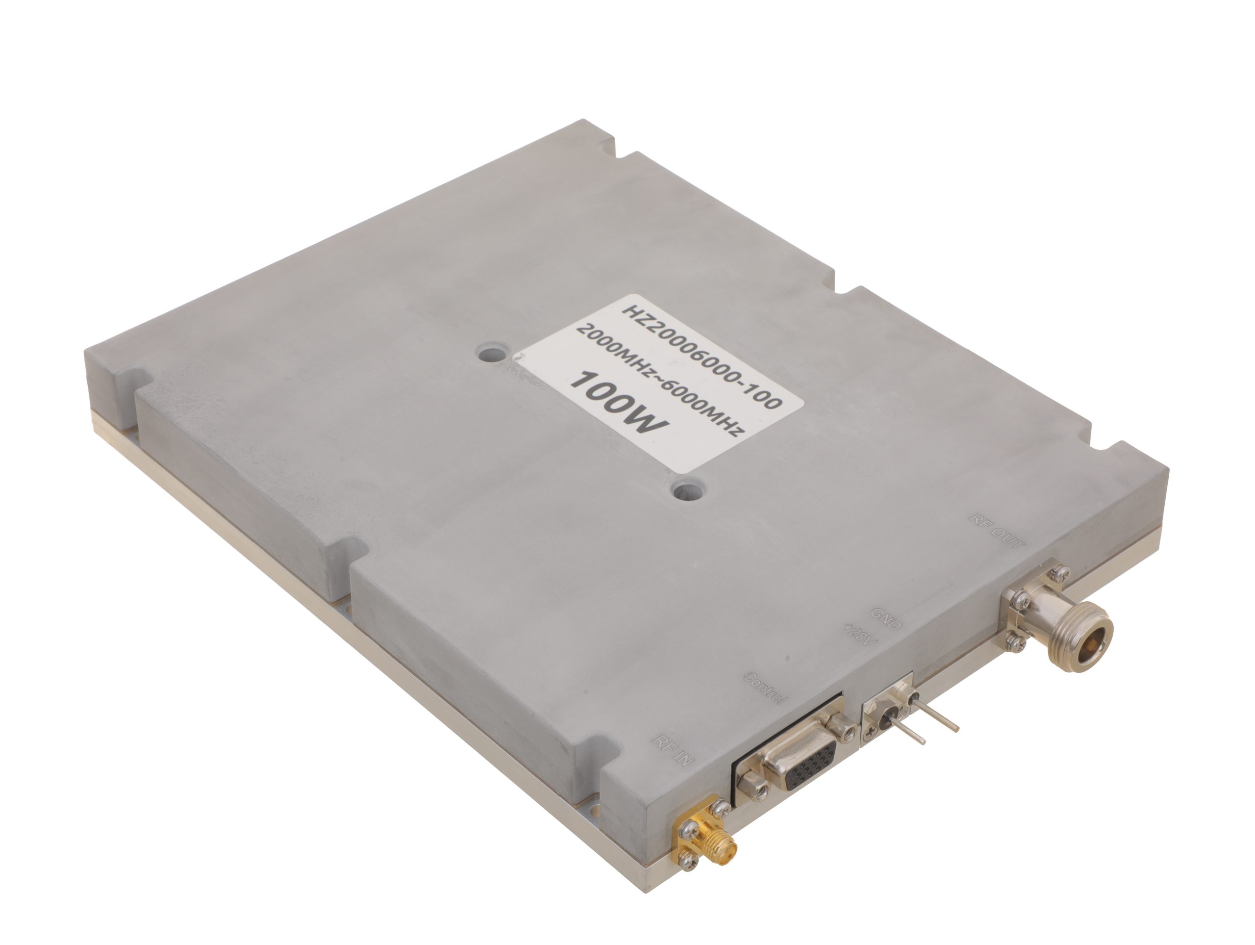 HZ20006000-100NA1Open English PDF ↗ | 80 / 100 W | 19 / 24 A | 200 × 158 × 25 mm | SMA-F / N-F | 15-pin D-Sub |
| 150 W | 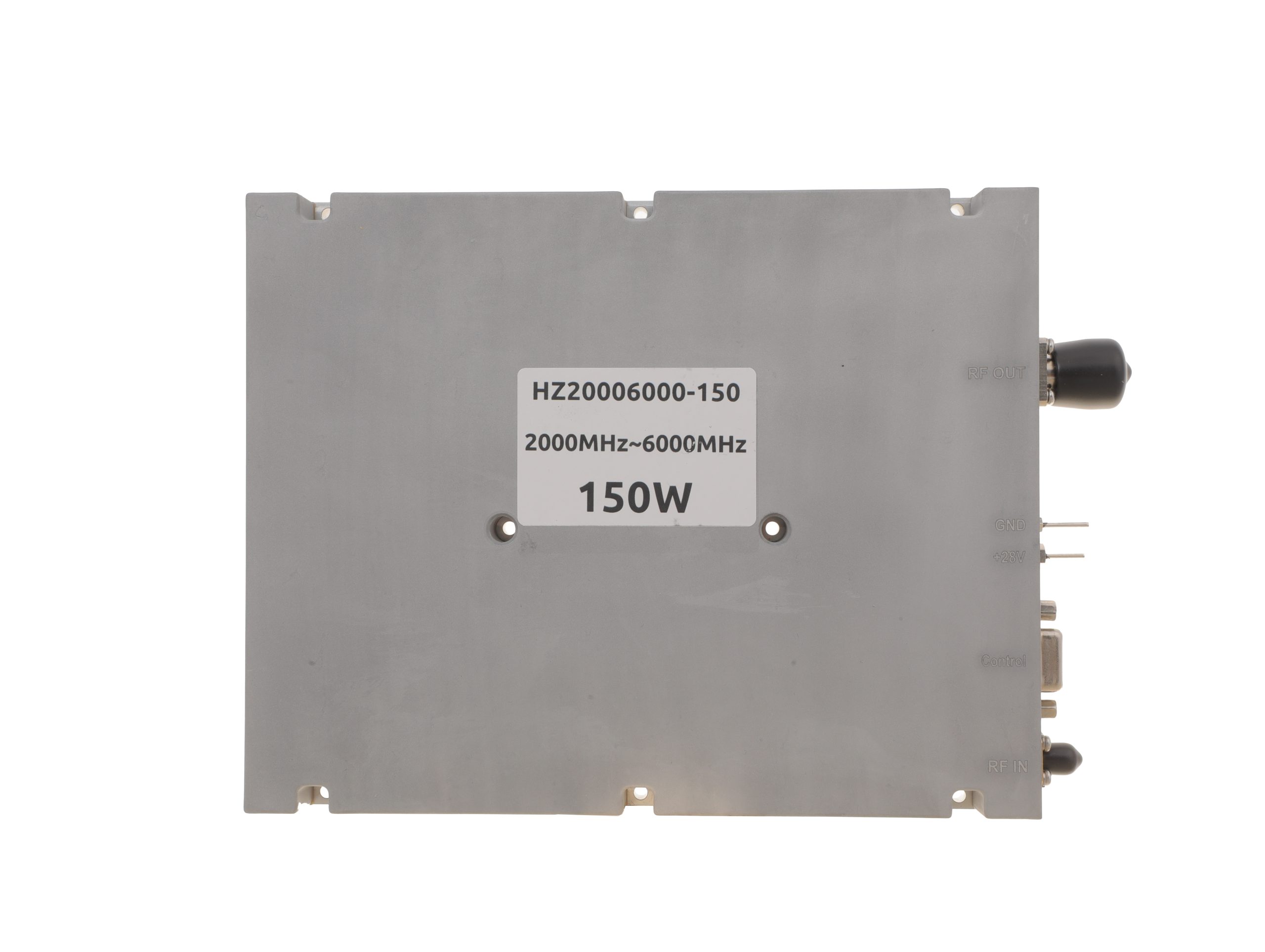 HZ20006000-150NA1Open English PDF ↗ | 120 / 150 W | 22 / 27 A | 200 × 158 × 25 mm | SMA-F / N-F | 15-pin D-Sub |
| 200 W | 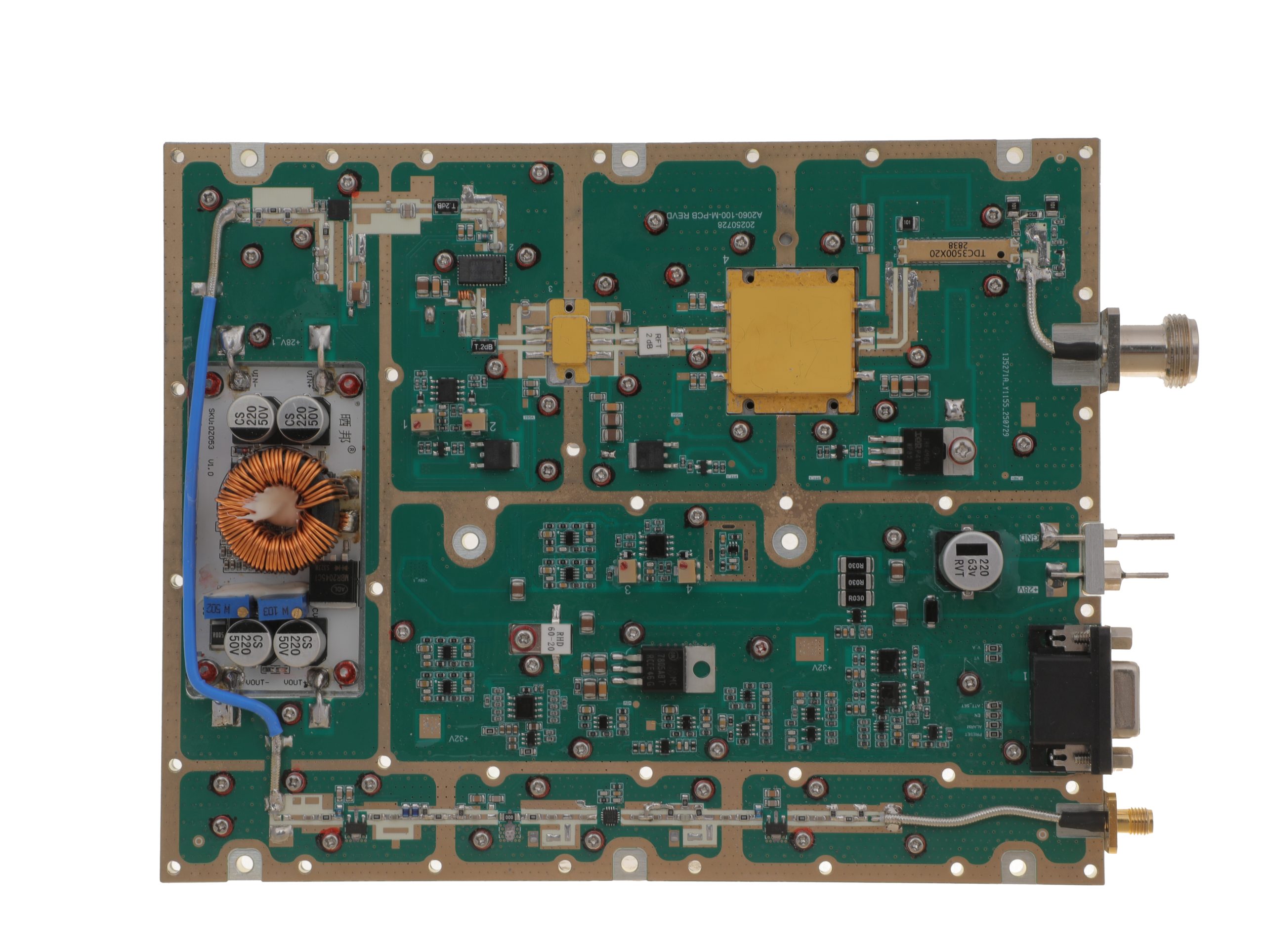 HZ20006000-200NA1Open English PDF ↗ | 160 / 200 W | 29 / 36 A | 280 × 250 × 25 mm | SMA-F / N-F | 15-pin D-Sub |
Review the applicable model’s English PDF datasheet for RF input drive, protection, and optional-function details.
Conclusion
RF connector overheating cannot be assigned to contact resistance or mismatch from temperature or reflection readings alone. Credible thermal observations, corrected RF measurements, and clearly separated offline evidence can narrow the likely mechanisms. Contact loss and mismatch may coexist, and low upstream REV does not exclude downstream problems.
This approach supports fault prioritization and controlled retest decisions. It does not establish a connector-specific temperature limit, prove the internal failure point, or authorize continued operation without the required acceptance evidence.
Before releasing the interface, preserve the staged measurement record, identify the remaining uncertainty, and compare the corrective retest with the approved operating and acceptance conditions.
Where manufacturer input is needed, provide the PA model/S/N and both connector identities; frequency, actual forward-power values and measurement definitions, waveform and duty cycle; load, reflection, installation, cooling, and operating duration; qualified thermal observations; corrected FWD/REV with reference planes; available path-loss or S11/S21 results and their measurement states; protection history, interventions, and the required retest/reporting scope.
The RF SKYPOWER engineering team can review those interface and verification requirements without assuming that the field evidence has already established a specific connector defect.