










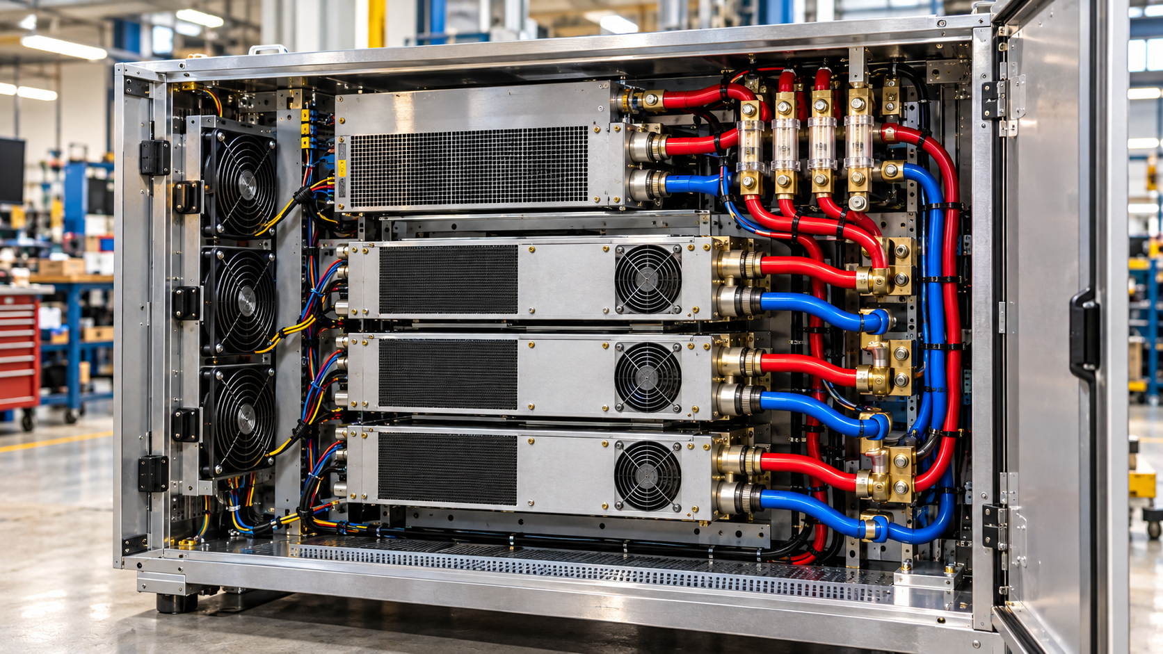
For a multi-PA system, PSU transient current margin depends on the largest DC load allowed by the control sequence, including simultaneous enable and restart events. The PSU must also keep every amplifier’s input voltage within approved limits while the load rises, falls, and settles.
An RF amplifier power supply transient test needs two kinds of evidence: the PSU’s current capability under the intended operating conditions and its measured voltage response to the actual load changes.
Average current figures are a starting point, not a PSU selection result. A supply with adequate continuous current can still enter current limit during a rapid PA enable event. A stable voltage reading at the PSU output may also hide a larger drop at an amplifier’s input terminals.
The selection depends on which PAs can switch together, how their current waveforms overlap, and whether the PSU and installed DC distribution can support those events within the approved operating limits.
1. Which DC Current Peak Actually Matters for PSU Selection?
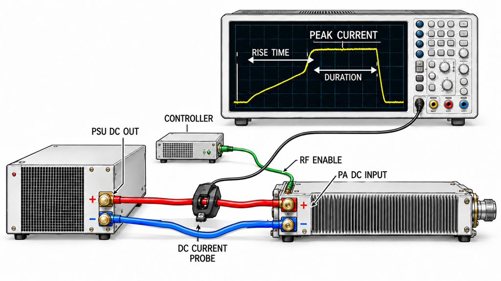
The relevant current peak is the highest DC demand the connected loads can place on the PSU during an allowed operating event. Record its amplitude, rise time, duration, repetition, and measurement location. A peak-current figure without those conditions tells an engineer little about the supply needed.
PA-side startup current and the PSU’s input inrush are different events. For DC output sizing, measure the current demanded by the connected PA loads at the PSU output. Input-side inrush belongs to the upstream AC supply and protection assessment; it cannot substitute for a measurement of PA-side DC demand.
The PA current record should distinguish five operating conditions:
- PA-side startup current: Current drawn when PA circuitry is energized, including input-capacitor charging visible at the measurement point.
- RF enable transient: The change in DC current after an amplifier receives a valid enable command.
- Full-power DC current: Current drawn at a stated RF output, frequency, waveform, duty cycle, and operating condition.
- Thermal steady-state current: Current after the amplifier reaches the specified thermal condition.
- Repeated transition current: Current associated with successive enable, disable, restart, or RF operating-state changes.
Full-power current is relevant to continuous loading, but it may miss a brief startup or enable peak. Cold startup and warm re-enable can produce different current profiles.
The timing of an enable command does not establish the rise time of the DC current. Even if a PA supports rapid enable/disable control, evaluate the PSU against the current waveform rather than the command specification.
An RF PA current alarm during startup calls for a separate diagnosis. During PSU selection, establish the expected current profile first. This helps distinguish the load the system is designed to produce from an abnormal event requiring investigation.
Ask for a current trace tied to each permitted operating event. If the supplier provides only a maximum current figure, request the missing timing and measurement conditions before using it to size the PSU.
2. How Do Simultaneous RF PA Transitions Build the Worst Load Step?
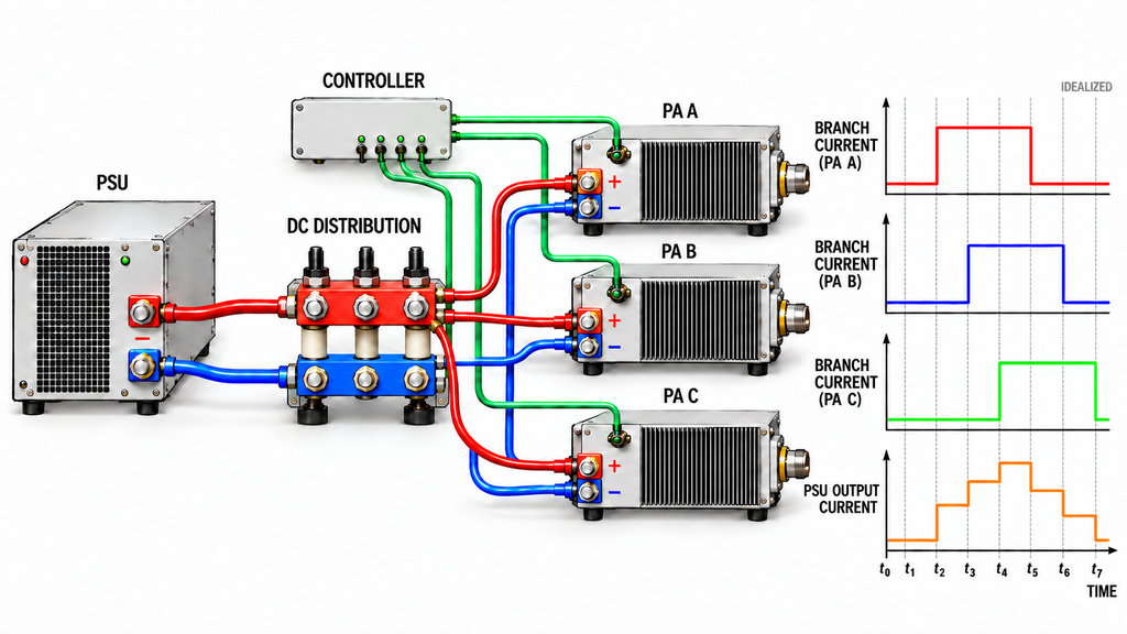
Several PAs sharing one supply do not necessarily reach maximum current at the same moment. The controller’s switching sequence determines how much of each current waveform overlaps.
In a multi-PA cabinet, the PSU supplies the amplifiers, auxiliary loads, and charging current associated with the DC distribution network. The combined load changes as modules enable, alter their RF operating state, or recover from an interruption.
Adding time-aligned PA branch currents is a useful starting point. For fast events, however, the current measured at the PSU output may differ from the branch-current sum. Bus capacitors and local energy storage can supply or absorb current during a transition. Identify the measurement point on every waveform so these differences can be interpreted correctly.
Build the load case from operating combinations the controller permits.
| Operating event | Allowed concurrent PA combination | Baseline current | Incremental current | Current rise time | Hold / repetition condition | Evidence status |
|---|---|---|---|---|---|---|
| Initial DC energization | Loads energized by approved startup sequence | Unloaded output or defined standby load | PA-side charging and startup demand | Measure at PSU output | Cold start; permitted restart | Startup trace required |
| Single PA enable | One PA changes from standby to specified RF state | Other PAs and auxiliaries active | Current increase of enabled PA | Measure from current trace | RF state and duration | Branch and total traces required |
| Simultaneous PA enable | Maximum controller-permitted combination | Defined standby or active baseline | Overlapping PA current increases | Measure branch and combined transitions | Worst permitted timing skew | Controller timing evidence required |
| RF operating-state change | PAs allowed to change state together | Defined prior RF state | Positive or negative current change | Measure actual transition | Frequency, waveform, duty, repetition | Operating-state traces required |
| Re-enable or retry | Combination allowed after interruption or fault | Defined recovery state | Restart and re-enable demand | Measure each permitted retry | Minimum retry interval | Recovery-sequence evidence required |
| Load release | Maximum permitted disable or output reduction | Defined active combination | Negative current step | N/A; record fall time in event trace | Fastest permitted release | Voltage-overshoot evidence required |
A staggered-enable sequence can reduce peak demand if the controller enforces it. Verify the timing under permitted command skew, restart conditions, communication failures, and automatic retries. If a recovery sequence can enable several PAs together, include that combination in the PSU load case.
Adding every independent PA maximum can also overstate demand by combining operating states that cannot occur together. The sum may be useful for conservative screening, but the verified system peak requires timing evidence.
If the controller’s behavior is uncertain, retain the credible simultaneous-transition case until the switching sequence is confirmed. Use the resulting time-aligned current profile as the load specification for PSU comparison.
3. Can the PSU’s Continuous and Peak Ratings Cover That Load?
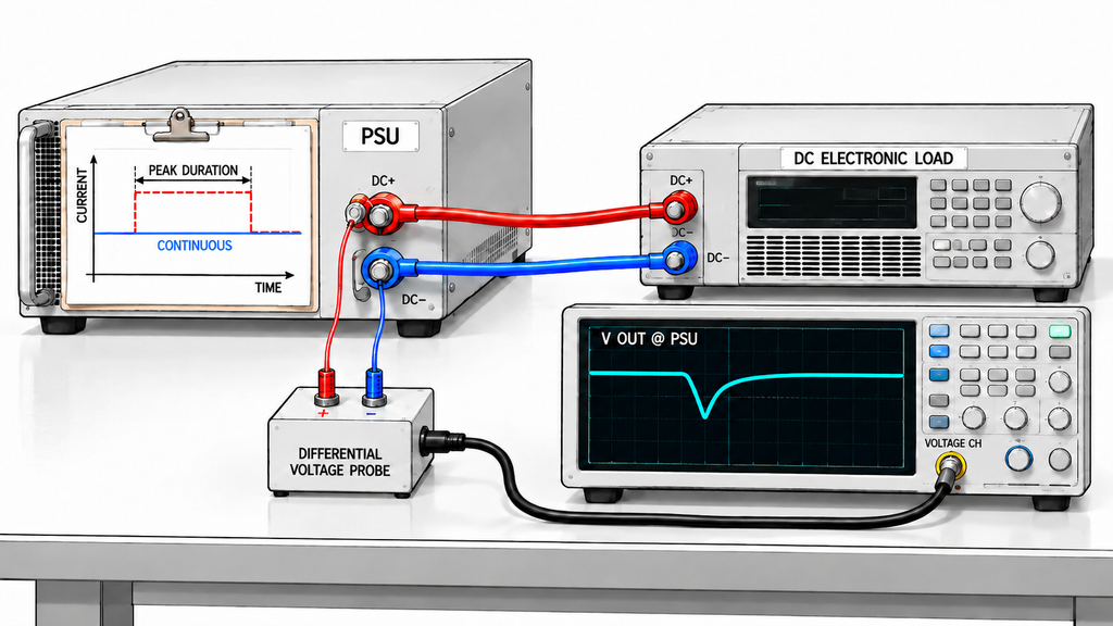
PSU selection requires two checks. The documented current ratings must cover the expected load, and the supply must demonstrate acceptable voltage recovery and protection behavior when that load changes.
Gate 1: Check the PSU’s current-rating envelope.
The continuous rating must support sustained PA and auxiliary current after applying the relevant input-voltage, ambient-temperature, and cooling derating.
Peak-current capability requires a separate check. A PSU may permit temporary overload for a specified duration, at a limited repetition rate, or under restricted environmental conditions. That peak rating does not establish unlimited operation at the same current.
Compare the expected load against:
- Maximum sustained combined current.
- Peak current and load-step magnitude.
- Current rise time.
- Duration of the elevated current.
- Repetition interval.
- Input-voltage and thermal derating.
A supply rated above the continuous load can still enter current limit during a fast transition. Another supply may tolerate a single peak but struggle when the event repeats before its thermal or protection conditions recover.
A fixed headroom percentage cannot resolve these differences. The required allowance depends on the load waveform and the PSU’s specified behavior.
Gate 2: Verify the dynamic response.
A PSU that meets the published current ratings still has to maintain acceptable voltage during load application and release. Its current capacity alone says nothing about the magnitude of the voltage dip, overshoot, or recovery time.
Candidates whose documented ratings cover the intended load can proceed to dynamic testing. If a supplier cannot establish the peak-current duration, repetition allowance, or applicable derating, hold the comparison until that evidence is available. Missing documentation is not proof of PSU failure.
4. How Should a Multi-PA Load-Step Test Be Reproduced?
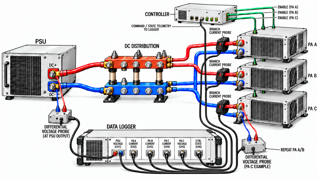
A load-step test should reproduce a current event the system can produce.
A programmable electronic load can generate controlled current steps and make PSU comparisons repeatable. It cannot automatically reproduce a PA’s input-capacitor charging, RF-state changes, control timing, or interaction with the installed DC distribution.
Keep the two test stages separate.
Source-level qualification applies a defined load-current profile directly to the candidate PSU. Record the actual current step, PSU output voltage, recovery, and protection response under the stated input-voltage, temperature, and cooling conditions.
Representative PA-system validation uses the intended PA modules and control sequence, or a validated equivalent, together with the relevant DC distribution path. This checks whether the source-level result holds when the supply drives the intended system.
During an actual multi-PA transition, capture PSU output current, individual PA branch currents where practical, and the enable or operating-state commands on a common time base. When branch measurements are unavailable, separately validated module waveforms may support the analysis if their timing and applicability are established.
Measure PSU voltage across its DC output and designated return terminals. Measure PA input voltage across each module’s DC+ and DC− terminals. Suitable differential or isolated measurements may be necessary; chassis ground should not be assumed to be the correct DC return. Check probe grounding, bandwidth, and loading before comparing fast transients between channels.
Current rise time needs a consistent measurement definition. Record how the start and end of the transition were determined, together with the trigger, probe response, acquisition bandwidth, sampling interval, and relevant timing uncertainty. The enable-command timestamp does not necessarily mark the beginning of the current rise.
Test both directions of the load change. Applying current can produce voltage sag or current limiting; removing it can produce overshoot. Repeat the transitions when the controller permits closely spaced events.
For tests using actual RF amplifiers, keep the RF input, output loading, frequency, waveform, and duty cycle consistent with the intended operating condition. A current trace collected under an unrelated RF state may not represent the cabinet’s worst load.
The completed record should align the controller command, each PA’s current response, total PSU output current, and voltage waveform in time. Without that correlation, the source of a measured peak remains uncertain.
5. What Voltage and Protection Evidence Proves Transient Margin?
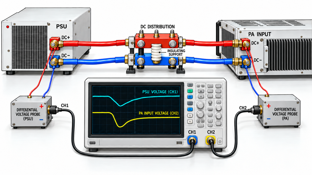
Gate 2 passes when the measured voltage and protection behavior meet the approved limits for the specified load event.
For each qualifying load application and release, record:
- Minimum voltage during the positive current step.
- Maximum voltage during load release or recovery.
- Time to settle within the approved voltage band for the resulting operating state.
- Any PSU current limiting, foldback, shutdown, or fault indication.
- Any unintended PA reset, disable, alarm, or loss of the required operating state.
A recovery-time result is incomplete without a voltage settling band. The test needs both the acceptable band and the maximum time allowed to reach it. These limits must come from the applicable PA specifications and system requirements; there is no universal recovery time or voltage-dip percentage for every 28 V amplifier installation.
The required 28 V RF PA voltage margin must be assessed at the amplifier terminals under load, not inferred from the PSU output setting.
Cables, connectors, protection devices, and distribution impedance can create voltage drops between the PSU and the PA. A stable source-output trace may therefore coexist with an unacceptable PA-terminal transient.
A bench test conducted only at the PSU output qualifies the response at that reference plane. PA-terminal performance still requires the relevant distribution path to be included and measured.
Protection behavior needs the same care. A brief current-limit event is not automatically acceptable because the PSU later recovers. If the event takes the amplifier outside its approved voltage range or causes a prohibited reset, the configuration fails that acceptance condition.
A system can also experience an unacceptable voltage transient without reporting a fault. The measured waveform must meet the specified limits.
For the tested event, retain the current profile, voltage minimum and maximum, recovery time, settling band, and PSU or PA protection state. Gate 1 and Gate 2 must both be supported before qualifying a candidate for that source-level load condition.
6. When Is PSU Bench Performance Not Enough for Cabinet Approval?
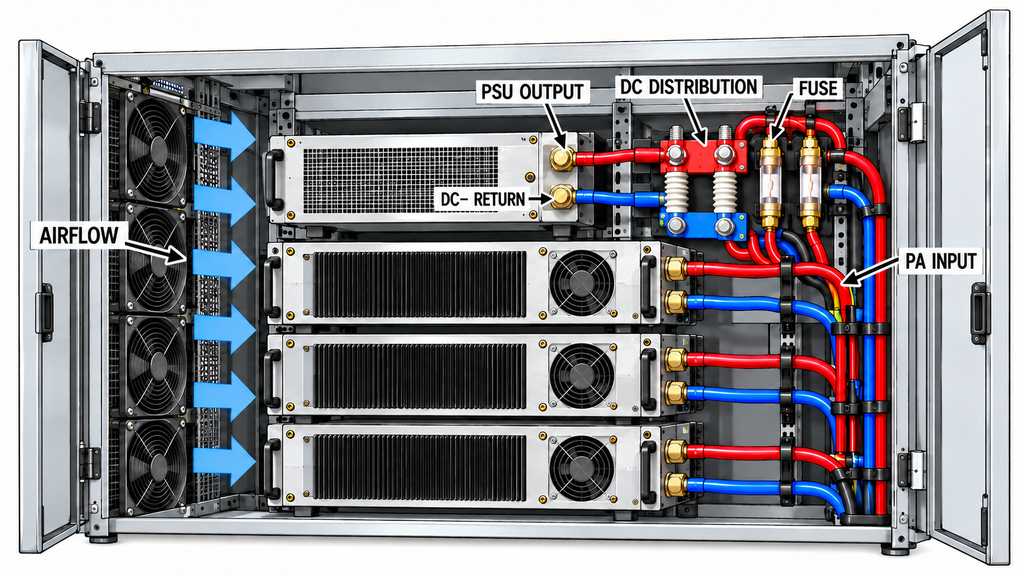
A PSU can pass the source-level test and perform differently after installation.
Cable length and conductor size affect the delivery path. Connectors, fuses, distribution hardware, and local capacitance can change the transient response at individual PA inputs. Cabinet airflow and heat accumulation may also reduce the PSU’s available output capability.
Even with acceptable voltage at the PSU terminals, shared DC bus interaction can disturb individual PA branches when several loads switch together.
Replay the approved worst-case transitions using the actual or representative cabinet wiring, distribution components, cooling conditions, and concurrent loads. Measure voltage at the PSU output and the relevant PA input terminals, including branches most likely to experience significant distribution-related drops.
The comparison separates three outcomes:
- PSU-output limit exceeded: Investigate the source-level configuration or select a different supply.
- PSU output acceptable, PA-terminal limit exceeded: Evaluate the installed distribution path and interaction among connected loads.
- Both reference planes acceptable: The tested cabinet configuration may proceed toward approval if its protection behavior also meets the agreed criteria.
The measurements identify where the electrical response first exceeds an approved limit. Detailed shared-bus fault diagnosis remains a separate task.
Record the conditions represented by the cabinet test. Passing at one ambient temperature, input voltage, or PA combination does not establish performance at untested extremes.
7. What Must Be Recorded Before Selecting the PSU?
A procurement record should connect every PSU candidate to the load event it was tested against. Two suppliers can report acceptable transient performance while using different current steps, timing, or voltage limits.
Identify the PSU manufacturer, model, and revision; continuous and peak ratings; relevant derating; PA configuration; allowed switching and retry behavior; and the waveform used to reproduce the load.
The record also needs the voltage measurement points, approved operating limits, settling band, recovery time, protection response, and test conditions. Keep the supporting waveform or report reference with the decision.
The table below is a qualification template. It contains no assumed test results.
| Candidate PSU | Rating / derating condition | Load-step event | Measured voltage dip / recovery | Protection response | Approved limit | Decision / evidence status |
|---|---|---|---|---|---|---|
| Model and revision — rating review | Continuous and peak ratings; duration, repetition, inlet, ambient, cooling | Worst permitted time-aligned load | Not applicable to rating review | Specified limit behavior | Approved current envelope | Rating eligible only if Gate 1 is documented |
| Same candidate — source test | Actual PSU test conditions | Event ID; starting/ending current; rise/fall time; hold/repeat intervals | PSU output min/max and settling time | PSU limit, fault, and restart state | Source voltage band and recovery time | Gate 1/2 decision; waveform or report ID; missing evidence |
| Same candidate — cabinet replay | Installed operating and derating conditions | Enforced PA overlap, retry, and release | PSU and PA-terminal min/max; settling time | PSU and PA protection states | PA-specific and system limits | Cabinet qualified only for verified conditions |
Qualified means the candidate met the applicable current-rating and measured-response requirements under the recorded conditions. Conditional applies when one stage is complete, such as source-level testing, but installed validation remains outstanding.
Not comparable yet means necessary ratings, waveforms, conditions, or acceptance limits are missing. Not qualified requires evidence of failure against an agreed requirement.
Classify a candidate with missing waveforms as not comparable yet. A catalog peak-current rating alone also leaves the dynamic response unverified.
For a C-UAS installation, this record provides the DC-transient evidence needed when choosing RF power amplifier modules for the complete system. RF output suitability, thermal acceptance, and overall system readiness still require their own supporting evidence.
Compare suppliers using equivalent load-current profiles, transition timing, repetition conditions, measurement reference planes, and acceptance limits. Where test conditions differ, normalize the evidence explicitly or keep the candidates in the not-directly-comparable category.
Conclusion
A suitable PSU for multiple RF power amplifiers must satisfy two requirements: its documented, derated current capacity must cover the highest permitted time-aligned load, and its measured voltage and protection response must meet the approved limits.
Average PA current and catalog peak-current ratings leave the dynamic response unverified. A PSU-only bench test leaves PA-terminal voltage under installed conditions unverified.
Qualify a candidate only for the operating conditions and limits supported by its evidence. Incomplete results may justify conditional qualification or a decision hold; a finding of nonqualification requires failure against an agreed criterion. Voltage thresholds, recovery times, and suitability for a particular PSU–PA combination remain model- and project-specific.
Before comparing suppliers, confirm the allowed PA switching and retry states, obtain synchronized current and voltage traces, agree on the electrical limits, and record the results for the PSU and installed DC distribution.
For a system using RF SKYPOWER RF power amplifier modules, send the proposed PA models and quantities, RF operating conditions, control timing, expected current events, PSU ratings, DC distribution details, environmental conditions, and voltage/protection limits through the RF SKYPOWER engineering inquiry channel. These details allow the proposed PSU and amplifier configuration to be reviewed against the intended operating conditions.