











RF PA output drops after cabinet installation do not necessarily mean the amplifier itself has degraded. The difference may come from the installed RF path, DC delivery, temperature, load mismatch, or the way power is measured.
Start by comparing corrected output at the PA’s RF OUT reference plane under equivalent bench and cabinet conditions. If the PA-port readings agree but the cabinet-end reading is lower, investigate the path between those two points. If PA-port output has changed, examine the RF input, DC supply, thermal conditions, load, and operating state.
Until the measurement planes and operating conditions are comparable, a lower cabinet reading does not establish PA degradation.
1. Did the RF PA Lose Output, or Did the Measurement Plane Change?
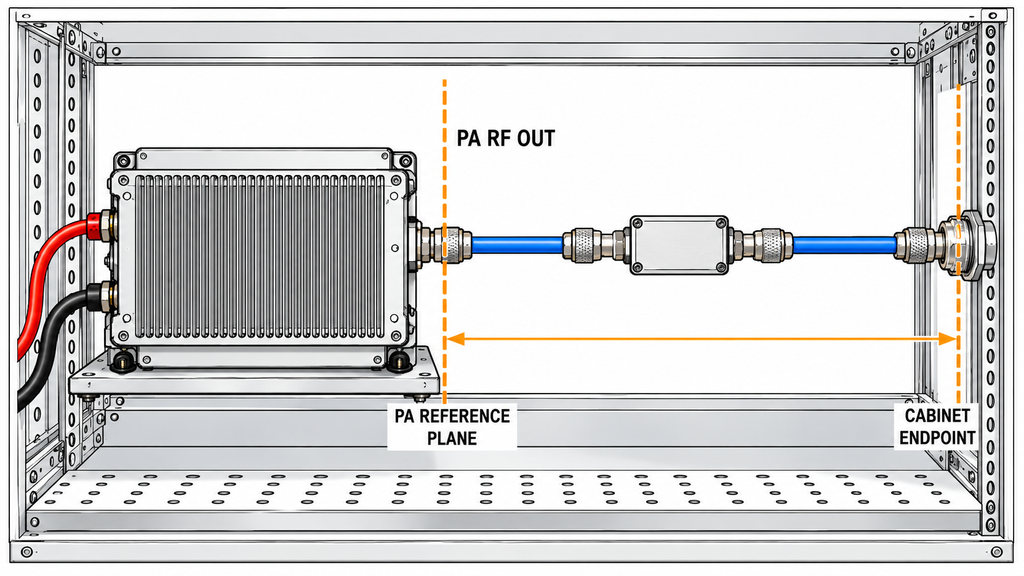
First, identify where each RF power reading was taken.
A bench test may measure power directly at the PA’s RF OUT reference plane through a calibrated measurement chain. After installation, the available reading may come from a directional coupler, distribution point, cabinet output connector, or another downstream location.
The two readings describe different physical points.
Between the PA and the cabinet endpoint, the installed path may contain coaxial cables, connectors, filters, switches, couplers, or other RF components. Power measured at the endpoint can differ from PA-port power because of path loss, load mismatch, and measurement-chain characteristics.
Classify the reported drop before troubleshooting:
- PA-port output change: Corrected output at the same PA reference plane differs between comparable bench and cabinet states.
- Downstream path difference: PA-port output remains comparable, but power at a defined cabinet endpoint is lower.
- Unresolved measurement difference: The reference planes, corrections, load conditions, or operating states are not documented well enough to support either finding.
Controller telemetry needs separate treatment. A lower displayed power value may reflect sensing, scaling, coupling, or timing differences. Compare it with an independent corrected RF measurement before treating it as a physical output change.
If the original bench result and the cabinet result were taken at different locations, establish a common reference plane first.
2. Which Bench and Cabinet Conditions Must Be Compared?
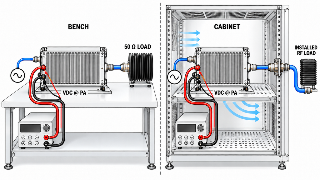
For each state, record the amplifier model and configuration, measurement date, frequency, RF input drive, waveform or modulation, duty cycle, enable state, instruments, calibration factors, and RF reference planes.
Measure DC voltage and current under load at the PA terminals. Record the relevant temperatures, cooling configuration, RF load, and protection or status indications. A nominal PSU setting cannot establish the voltage delivered to the amplifier during RF operation.
During RF amplifier system integration, mounting, power wiring, airflow, RF routing, and control connections may all change between the bench and the cabinet. Compare these conditions with the original RF power amplifier integration arrangement before attributing the output difference to the PA.
Time-stamp the measurements. A reading taken immediately after RF enable may differ from one taken during sustained operation. For intermittent faults, synchronize RF power, loaded DC voltage, current, temperature, and event records closely enough to determine which changes occurred first.
Keep the information needed to reconstruct both measurement chains: reference planes, coupling and attenuation factors, instrument corrections, power definitions, calibration conditions, and known mismatch limitations. Record the bench and cabinet loads separately.
These details determine whether the states are comparable, partially comparable, or not yet comparable. If a critical condition is missing, name the missing evidence and hold the corresponding conclusion.
3. How to Build a Bench-to-Cabinet Difference Record
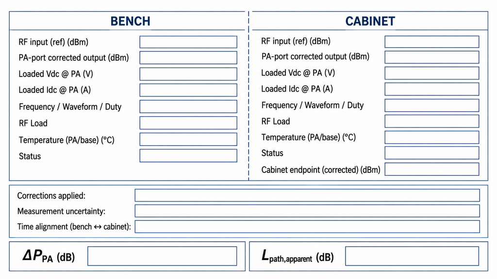
Record the bench and cabinet states side by side. Keep raw observations, corrected measurements, and engineering conclusions separate.
The comparison must distinguish corrected PA-port output from downstream cabinet power. DC, thermal, RF, and protection readings should also refer to the same operating interval wherever possible.
| Record item | Bench state | Cabinet state | Comparison or correction basis | Difference and decision |
|---|---|---|---|---|
| Actual RF input at PA port | Corrected input power, frequency, waveform, and timing | Same fields measured at the installed PA input | Common input reference plane and compatible RF stimulus | Determine whether the PA received comparable excitation |
| Corrected RF output at PA port | Output reading with applicable measurement-chain corrections | Output reading at the same defined PA reference plane | Compatible power metric, calibration, load condition, and uncertainty | Determine whether a PA-port output difference is demonstrated |
| Cabinet RF boundary and endpoint | Bench load and downstream measurement arrangement | Installed RF path and named cabinet endpoint | Identify additional components, reference planes, and path corrections | Separate the PA-port comparison from downstream power differences |
| PA-terminal Vdc and Idc | Loaded voltage and current with timestamps | Loaded voltage and current with timestamps | Same terminal reference and relevant operating interval | Identify a possible electrical operating-state difference |
| Temperature and cooling | Relevant temperatures, mounting, airflow, and operating duration | Corresponding installed conditions | Comparable thermal state or a documented difference | Determine whether thermal evidence requires further review |
| FWD, REV, and VSWR indications | Readings, source, and measurement conditions | Readings, source, and measurement conditions | Coupler definitions, calibration, directivity, load state, and timing | Identify a possible RF-load change without assuming protection was triggered |
| Control and protection state | Enable, alarm, shutdown, reset, and available event records | Corresponding installed states and event records | Model-specific state definitions and event chronology | Determine whether a state transition is evidenced and temporally relevant |
For comparable PA-port measurements, calculate the change in corrected output:
ΔP_PA (dB) = Pout,cabinet@PA (dBm) − Pout,bench@PA (dBm)
A negative ΔP_PA means the corrected cabinet-state reading is lower at the PA port. Report the difference with its measurement uncertainty. If the difference cannot be distinguished from that uncertainty, PA-port output degradation has not been demonstrated.
Evaluate downstream power separately. When both readings represent the same cabinet operating state and use compatible calibrated reference planes and power definitions, calculate the apparent loss:
L_path,apparent (dB) = Pout,cabinet@PA (dBm) − Pcabinet,endpoint (dBm)
Name the endpoint and document the corrections. This difference is not automatically a calibrated insertion-loss result. That interpretation depends on the measurement method and load conditions. Where mismatch or uncertainty materially affects the result, use the appropriate evaluation or correction method before assigning loss to the installed RF path.
ΔP_PA and L_path,apparent describe different boundaries. Combining them into one figure and calling it amplifier degradation would misrepresent the measurements.
The completed record should show which differences are supported, which remain conditional, and which measurements are still missing.
4. How to Find the First Changed Installation Boundary
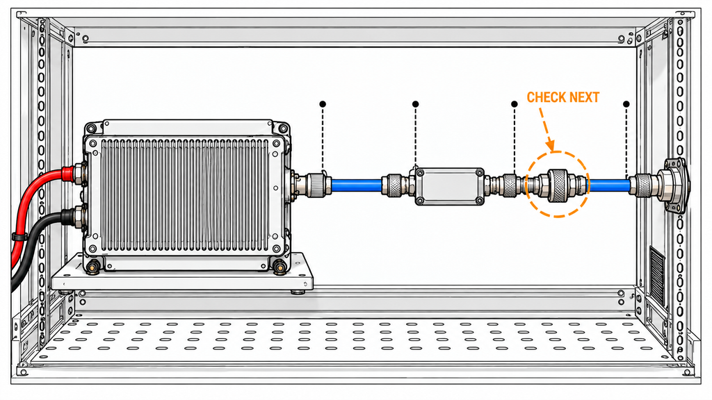
Trace the first verified divergence between the normalized bench and cabinet records.
Begin at the amplifier: compare RF input at the PA port, loaded DC voltage and current, control state, and relevant thermal conditions. Then compare corrected PA-port output before moving downstream through the installed RF path.
If input and PA-port output remain comparable while cabinet-end power falls, investigate the downstream path and measurement arrangement. If corrected PA-port output falls, check which electrical, thermal, RF-load, or control condition changed with it.
During isolation, change one condition at a time while keeping the others under control. A cable-routing change, for example, should not introduce an undocumented change in the amplifier load or measurement method.
Several boundaries may change together. RF mismatch can affect power transfer, sensed readings, and protection behavior. A shared DC distribution path may respond to changing current demand while cabinet airflow affects temperature.
These interactions matter during simultaneous multi-band RF operation. Enabling another PA channel may alter shared supply, thermal, or RF conditions, even when the original amplifier remains unchanged.
End the investigation with one documented outcome:
- First verified changed boundary identified: Comparable measurements establish the earliest observed divergence. Investigate that boundary next.
- Multiple changed boundaries remain unresolved: Evidence supports more than one interacting difference. Further isolation is required.
- Boundary cannot yet be localized: A specified measurement, correction, or operating-state record is missing.
These outcomes identify the next test. Confirming a root cause still requires an appropriate exclusion chain and repeatable verification.
5. What Do the DC, Thermal, RF, and Protection Differences Actually Prove?
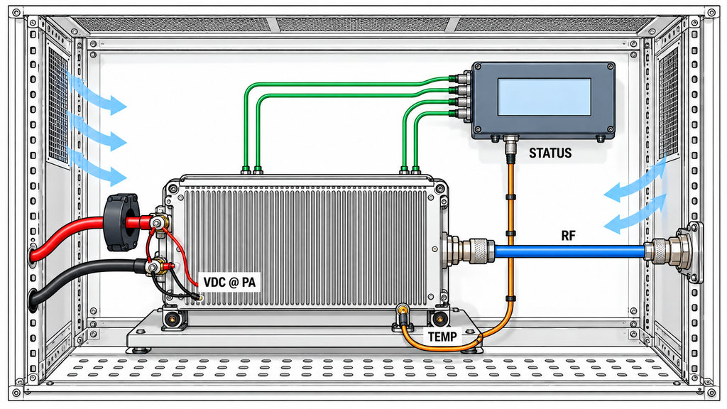
A repeatable change helps localize the investigation, but correlation alone cannot establish the mechanism causing lower output.
| Repeatable observation | Boundary to investigate | What remains to verify | Next specialist review | Decision stop |
|---|---|---|---|---|
| PA-port output remains comparable, but cabinet-end power is lower | Installed RF path, measurement endpoint, or load condition | Compatible power metrics, corrections, path losses, and mismatch effects | RF chain and cabinet routing | Do not attribute the difference to PA degradation |
| Loaded PA-terminal Vdc changes near the observed output change | DC delivery under the installed operating load | Timing, terminal voltage, current demand, and reproducibility | Power distribution and supply behavior | Do not declare a supply fault from correlation alone |
| Output changes with operating temperature or sustained duty | Mounting, cooling, thermal operating state, or protection response | Relevant temperature trend, stable operating conditions, and status records | Thermal integration | Do not infer thermal protection without supporting evidence |
| FWD, REV, or VSWR indications change with a protection event | RF load, sensing, and protection behavior | Coupler limitations, event order, actual load condition, and model-specific state definitions | RF mismatch and protection logic | Do not treat an indication alone as proof of the trigger or cause |
| Controller-reported output changes while an independent corrected RF measurement remains stable | Telemetry, sensing, scaling, or measurement synchronization | Controller definitions, correction factors, and simultaneous instrument records | Control and monitoring | Do not classify a display difference as physical output loss |
Measure voltage at the PA terminals during RF operation. A PSU set to 28 V may deliver a different voltage at the amplifier after cable and connector losses or a change in load current. The relevant distinction is between supply settings and the DC power conditions associated with RF PA output drops at the actual terminals.
Where the design permits, record RF amplifier baseplate temperature alongside Pout and duty cycle. Cabinet mounting and restricted airflow can change operating temperature, but a hotter enclosure alone does not prove thermal derating. Compare the measured trend and duty conditions with the installed RF PA heat generation and cooling capacity before investigating a thermal protection mechanism.
A changed RF load can affect both transferred power and the readings produced by a directional coupler. Assess the cabinet RF routing and installed-path loss with the applicable reference planes, corrections, and mismatch effects before blaming a particular connector or cable.
When investigating RF power amplifier load mismatch protection, compare the alarm or shutdown timestamp with the measured changes in Pout, FWD, REV, and VSWR. Without the model-specific state definitions and event chronology, the readings cannot establish which condition triggered protection or whether protection caused the output drop.
6. When Is the Cabinet Retest Ready for Engineering Review?

The retest is ready for engineering review when the records separate PA-port behavior from downstream cabinet behavior and show which bench and cabinet measurements can be compared.
The RF amplifier test report or equivalent cabinet retest record should retain the original readings, corrected values, reference planes, calibration information, operating conditions, and synchronized DC, thermal, RF, and protection records. If a condition changed between tests, document it instead of treating the two measurements as equivalent.
For temperature-dependent symptoms, record the actual stabilization period and operating state. A cold-state reading cannot establish sustained hot-state behavior.
A result at one frequency or duty condition also cannot establish performance across the amplifier’s full operating range. Any broader power claim needs the relevant frequency-dependent full-power RF PA evidence.
Classify the retest result:
- Comparable difference established: Corrected measurements show a reproducible difference at a specified reference plane under adequately matched conditions.
- Partially comparable: The evidence supports a narrower finding, but differences in operating conditions or measurement definitions limit the conclusion.
- PA-output degradation not demonstrated: A lower cabinet reading exists, but a reduction at the PA output reference plane has not been established.
These classifications support troubleshooting. They do not replace the approved acceptance limits, protection thresholds, permissible RF path loss, or model-specific project requirements.
Record the first verified changed boundary, any unresolved alternatives, and the next isolation test. After a corrective change, repeat the relevant measurements at the same reference planes under compatible conditions.
Conclusion
A lower cabinet-end power reading establishes PA degradation only when comparable, corrected measurements also confirm lower output at the PA’s RF OUT reference plane. Otherwise, the investigation must account for installed RF path behavior, operating conditions, and measurement differences.
A bench-to-cabinet comparison can locate the first verified changed boundary and identify the next test. It cannot independently establish root cause, model-specific acceptance limits, or full-band suitability. In particular, downstream cabinet power must not be presented as direct PA output without the appropriate measurement basis.
Before selecting a replacement amplifier, the engineering or procurement team should compare both states at defined reference planes, document corrections and uncertainty, and identify unresolved DC, thermal, RF-load, and control differences.
For a model-specific review, send the amplifier model and configuration, operating frequency, waveform, RF drive, duty conditions, PA-port and cabinet-end measurements, loaded PA-terminal voltage and current, temperatures, RF monitoring indications, protection records, and cabinet RF path details to the RF SKYPOWER engineering team.
The RF Power Amplifier Modules can then be evaluated against the documented operating requirements and the evidence available for the intended installation.