










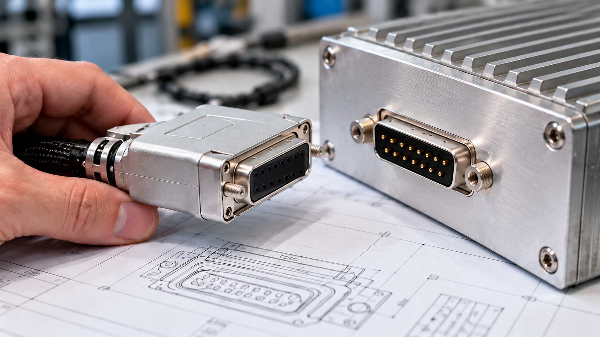
An RF amplifier D-Sub interface is ready for harness drawing release only when the buyer can trace every required connection from an approved amplifier interface definition to the correct physical contact, harness conductor, and destination terminal. Check the connector arrangement, pin-view orientation, electrical limits, default states, options, and revisions against the proposed manufacturing drawing.
This review covers the D-Sub interface portion of drawing release. Cable construction, assembly dimensions, manufacturing instructions, and other project requirements remain subject to their applicable approval controls. Document approval does not establish that the finished assembly has passed continuity, electrical, or system-level acceptance testing.
1. Why Is a D-Sub Pin List Not Enough to Release a Control Harness?
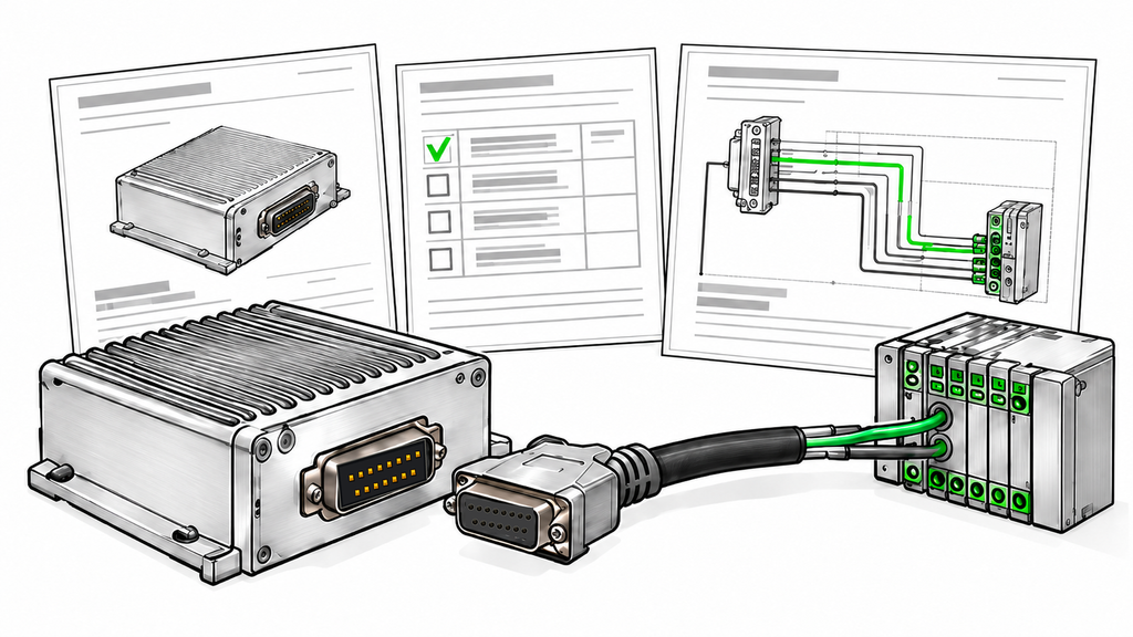
A pin list identifies electrical assignments. A manufacturing drawing must locate those assignments on the physical connector and show how they connect to the rest of the system.
The RF SKYPOWER HZ3001200-50 datasheet documents a compact nine-position DC interface with defined VDD, GND, and PA_EN assignments. The HZ3001700-50 datasheet shows a different integration architecture, using a 15-pin D-Sub control connector, a separate DC power connection, and additional control and monitoring functions, some of which are optional.
These two RF SKYPOWER models illustrate why harness specifications must follow the exact amplifier model and ordered configuration. The engineering team should confirm the mating connector, contact numbering, enabled functions, and destination wiring against the approved model-specific interface documentation before releasing the harness drawing.
Before drawing release, three controlled items must agree:
- The supplier’s connector and electrical interface documentation.
- The exact amplifier model and ordered configuration.
- The harness drawing, including its mating components and destination connections.
If the documents leave any of these relationships unresolved, request clarification before authorizing manufacture.
The harness drawing must map every required RF PA control-interface function to the correct physical contact, wire, destination, and applicable electrical definition. Harness release requires those definitions to be translated into an unambiguous, buildable wiring drawing.
2. Which D-Sub Connector and Pin View Must Be Defined?
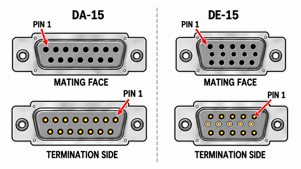
The drawing must identify the physical connector fitted to the amplifier and the exact mating connector selected for the harness.
“15-pin D-Sub” is not a complete connector designation. A standard-density DA-15 has 15 contacts arranged 8+7 in two rows, while a high-density DE-15 has 15 contacts arranged 5+5+5 in three rows.
Confirm the connector designation, contact gender, mounting arrangement, mating part number, contact type, and retaining hardware. Define backshell clearance, cable exit, shielding, and strain relief where they affect the assembly.
A numbering diagram viewed from the mating face cannot be copied directly to the termination side without accounting for the change in viewpoint. An otherwise correct pin list can produce a miswired harness if the manufacturer uses the wrong view.
Check that the drawing identifies:
- The amplifier connector and its numbered contact view.
- The mating harness connector and the view used for termination.
- Pin 1 and the orientation of both connector drawings.
- The destination connector or terminal arrangement at the opposite end of the harness.
- The approved mechanical components used in the assembly.
Each circuit needs a numbered contact-to-contact relationship. Cable color or a general signal label alone is insufficient. If the supplier drawing does not state its viewing direction, request a corrected drawing or written interpretation. Do not infer pin numbering from an equipment photograph.
3. What Electrical Information Must Each Assigned Pin Include?
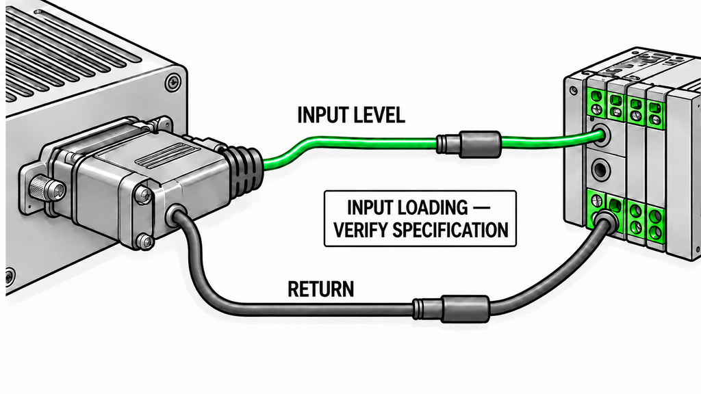
For harness release, the electrical definition must be usable as a wiring instruction. A label such as PA_EN or ALARM does not provide that instruction on its own.
Every populated connection should be traceable through:
Amplifier contact → identified harness conductor → destination connector contact or terminal
Show the applicable electrical reference, return path, and shield termination on the drawing. Identify reserved and unconnected contacts so the manufacturer does not have to interpret blank entries.
For DC supply and ground-return contacts, confirm the assigned pins, permissible operating voltage, current requirements, and any specified parallel-contact arrangement. If several contacts carry supply or return current, follow the approved design; one populated contact cannot automatically replace several specified contacts.
Wire size, contact rating, and termination method must suit the intended circuit; where a contact carries DC supply current, its mated-contact current rating must also be checked against the actual loading and installation conditions.
For discrete control inputs, confirm signal direction relative to the PA, accepted voltage levels, reference potential, input loading, and the treatment of an undriven connection. For alarm and status outputs, confirm output polarity, electrical drive characteristics, permissible loading, and any required external biasing.
Analog functions need their documented voltage or current range, scaling, reference, and loading conditions. Do not assign an assumed physical meaning to a voltage labelled as a temperature or power indication.
An output that requires an external pull-up cannot be wired as though it were a self-driven logic output without checking the circuit requirements. Likewise, a nominal 28 V PA supply does not imply that adjacent control contacts tolerate 28 V.
For RF amplifier system integration, compare the PA interface specification with the destination controller’s I/O requirements, then verify that the harness drawing implements a compatible connection. If either side lacks a required electrical definition, hold release of the affected connection until it is resolved.
4. What Must Be Defined About Default, Enable, and Alarm States?
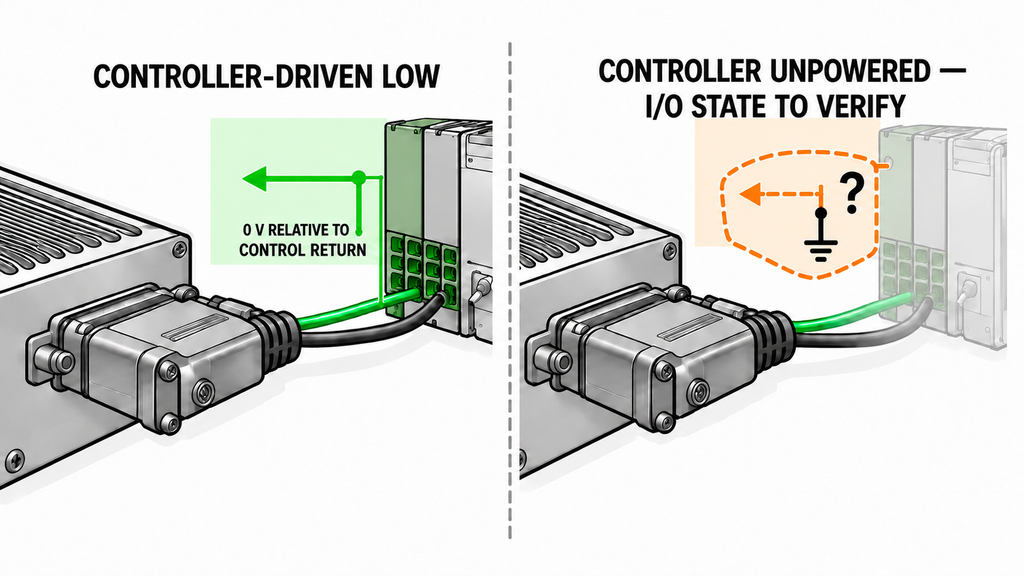
A harness can reproduce every numbered connection correctly and still produce an unintended control state. Review how the proposed wiring behaves during controller startup, disconnected control lines, controller power loss, PA power loss, and applicable fault or reset conditions.
For RF amplifier enable control, the label ENABLE does not establish the default state or the voltage required to switch the PA. For example, the HZ3001200-50 public specification states that PA_EN is ON at 0 V or when floating, and OFF when driven with 3.3 V or 5 V.
That statement applies to the documented model. It does not establish a universal RF PA enable convention or prove measurable RF output whenever the enable condition is ON.
For a harness using this interface, confirm whether the controller and external circuit maintain the intended electrical state under the relevant operating and disconnected conditions. A floating control line, a controller-driven low level, and an unpowered controller should not automatically be treated as electrically equivalent.
RF power amplifier alarm monitoring requires verified output-stage characteristics and loading limits. The HZ3001700-50 public specification describes certain alarm indications as 5 V signals, but that voltage designation alone does not define a compatible controller connection. Where a reset contact is provided, obtain its required electrical input definition as well. A reset pin alone does not define the system’s recovery policy.
Harness review checks whether the wiring implements the specified electrical states. The decisions about when to enable RF output, respond to an alarm, or attempt recovery belong to RF power amplifier control logic.
If the amplifier can remain powered while its controller is unpowered, obtain the interface limits for that condition. Hold release if the proposed wiring depends on an undocumented assumption about I/O isolation, back-feeding, or default bias.
5. How Do Optional Control Signals Affect D-Sub Harness Approval?
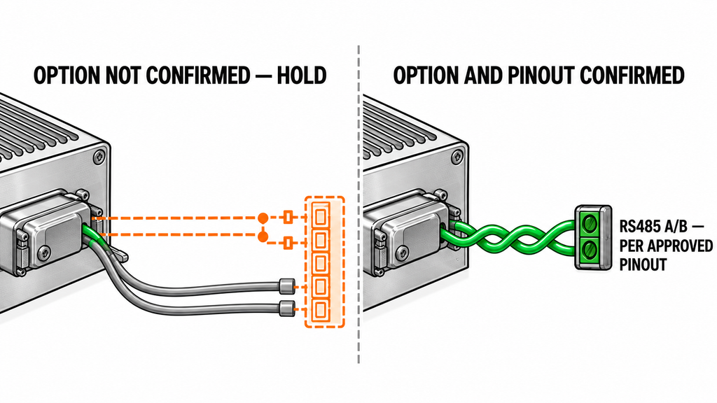
An optional function affects drawing release whenever the proposed harness depends on that function being fitted.
The public HZ3001700-50 specification marks several assignments as option-dependent and identifies HZ3001700-50-1 as the associated optional model. The noted functions include RS485 communication and certain alarm or attenuation-control signals.
For each option-dependent contact, confirm the ordered model suffix, fitted function, contact assignment, and interface revision. The public option note alone does not confirm what is fitted to the purchased unit.
For an RF amplifier RS485 control connection, identify the differential pair and any required reference, termination, or biasing connections on the harness drawing, provided the ordered configuration includes that function. An RS485 label alone does not establish the amplifier’s physical pin assignment; that must come from the approved module interface documentation.
Command definitions and communication timing are separate from contact assignment. A successful AT command response does not by itself prove that RF output has reached the required ready state.
Leave connections for an unconfirmed option unresolved until the supplier identifies the applicable configuration. A contact that is unused in one variant cannot be assumed to serve the same purpose in another.
6. Which Model, Option, and Revision Must Match the Interface Drawing?
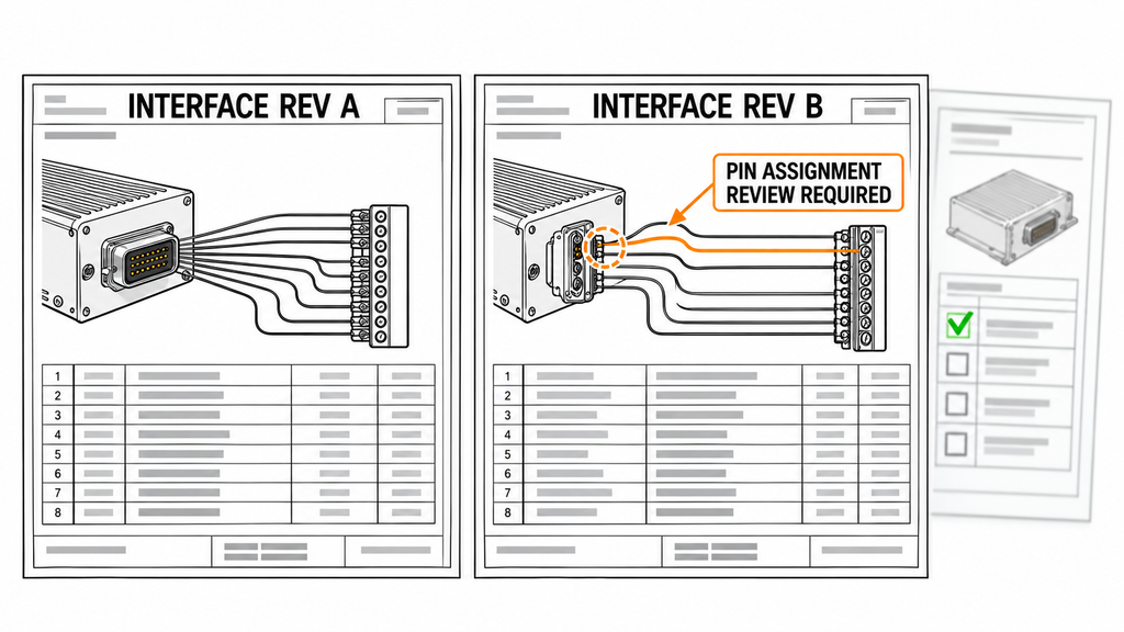
Tie the harness drawing approval to the exact ordered model, option suffix, applicable hardware revision, controlled interface drawing, and harness drawing revision. Include firmware or protocol revisions where they affect the electrical interface or the functions carried through the connector.
A public sales datasheet can provide a starting point, but publication alone does not make it the approved manufacturing reference for an order. If the datasheet, connector outline, and interface specification have different issue dates or revision identifiers, ask the supplier which document controls the interface.
Changes that may require harness drawing review include:
- A different connector, mating component, or contact arrangement.
- Reassignment of a contact or a change from
NCto an active function. - A revised input threshold, output type, or permissible electrical load.
- A change in enable, reset, or default-state behavior.
- A changed option configuration or communication pin assignment.
A firmware update does not automatically require a wiring change. Determine its interface impact from the supplier’s revision information.
RF SKYPOWER’s standard wideband RF power amplifier families span multiple frequency and power classes, including both 9-pin and 15-pin D-Sub control configurations. These model-specific differences make accurate amplifier identification an essential part of harness planning and interface documentation.
Wideband RF PA Modules
Select a frequency band to compare standard 30 W–200 W models and open the applicable English PDF datasheets.
30–512 MHz · 5 standard models
| Power | Model / PDF | Psat min. / typ. | Current typ. / max. | Dimensions | RF input / output | Control |
|---|---|---|---|---|---|---|
| 30 W | 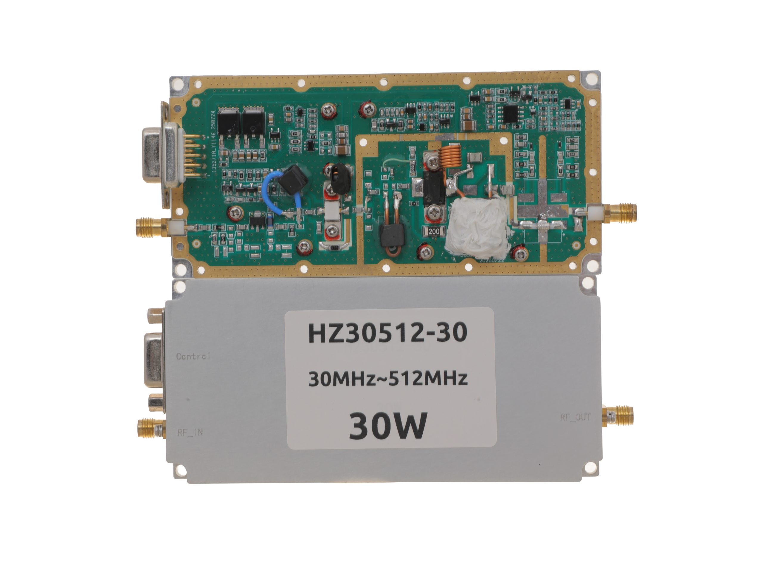 HZ30512-30NA1Open English PDF ↗ | 25 / 30 W | 3.2 / 4 A | 125 × 59 × 21.5 mmWeight: 0.5 kg | SMA-KFD46 / SMA-KFD46 | 9-pin D-Sub |
| 50 W | 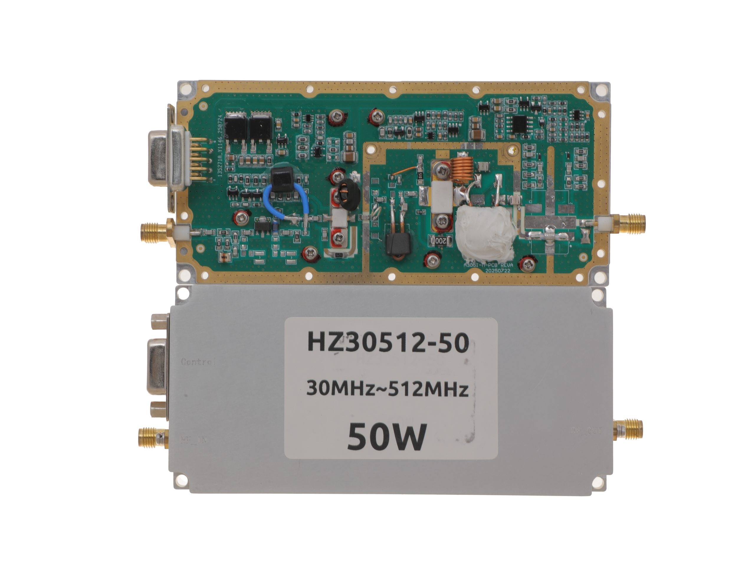 HZ30512-50NA1Open English PDF ↗ | 40 / 50 W | 7.2 / 9 A | 125 × 59 × 21.5 mmWeight: 0.5 kg | SMA-KFD46 / SMA-KFD46 | 9-pin D-Sub |
| 100 W | 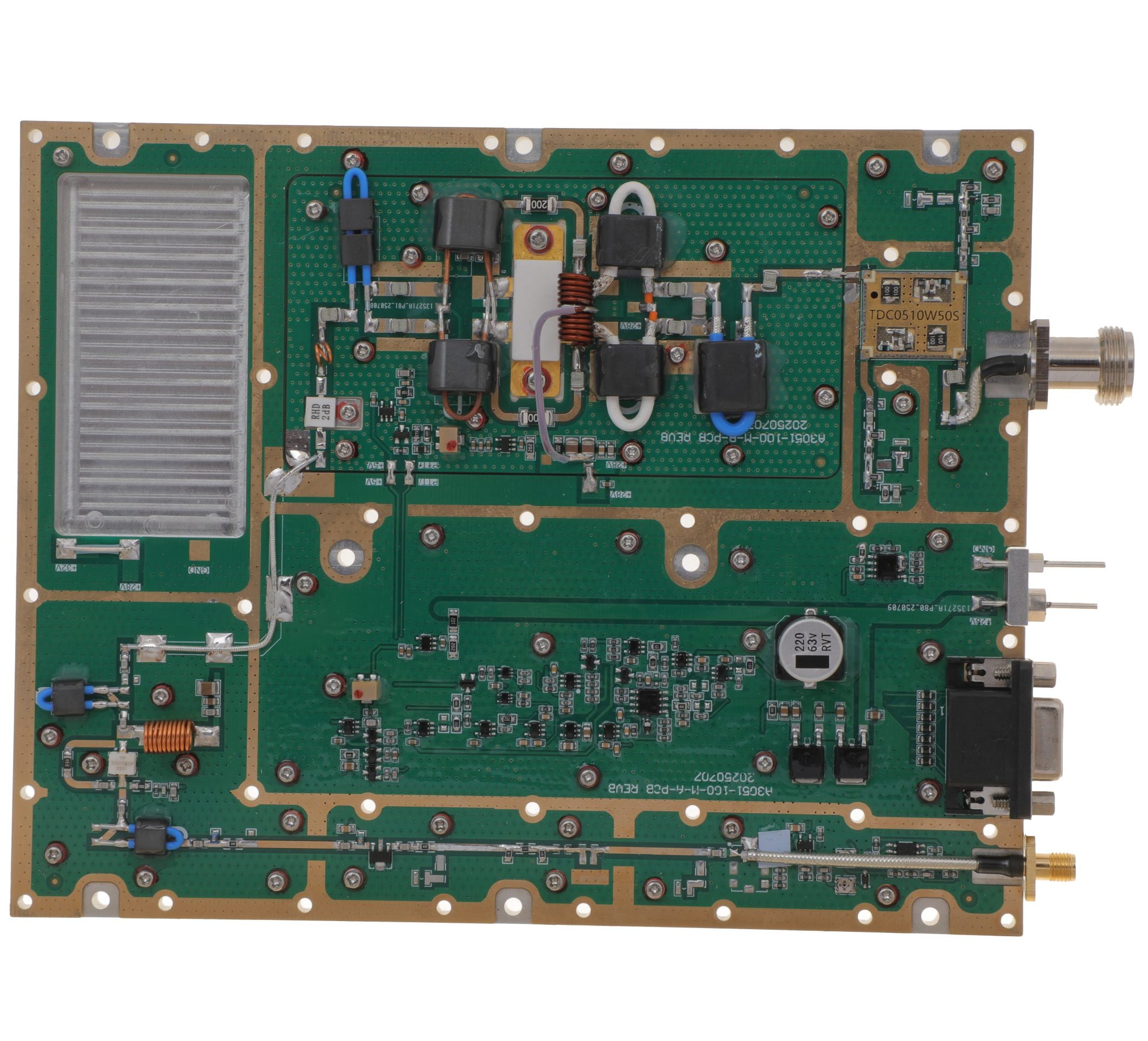 HZ30512-100NA1Open English PDF ↗ | 80 / 100 W | 14.5 / 18 A | 160 × 120 × 25 mmWeight: 1.4 kg | SMA-F / N-F | 15-pin D-Sub |
| 150 W | 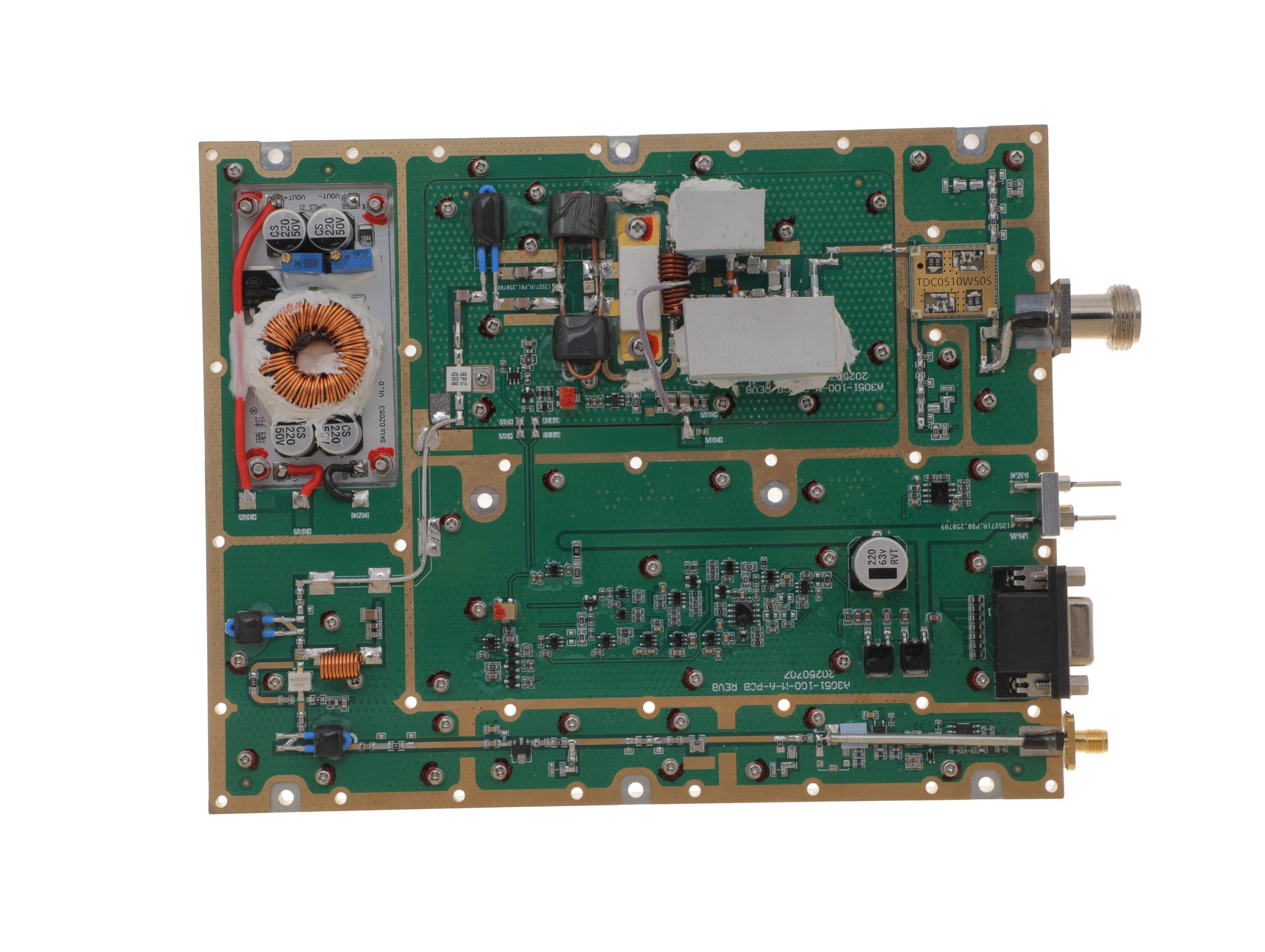 HZ30512-150NA1Open English PDF ↗ | 120 / 150 W | 16 / 20 A | 200 × 158 × 25 mmWeight: 1.4 kg | SMA-F / N-F | 15-pin D-Sub |
| 200 W | 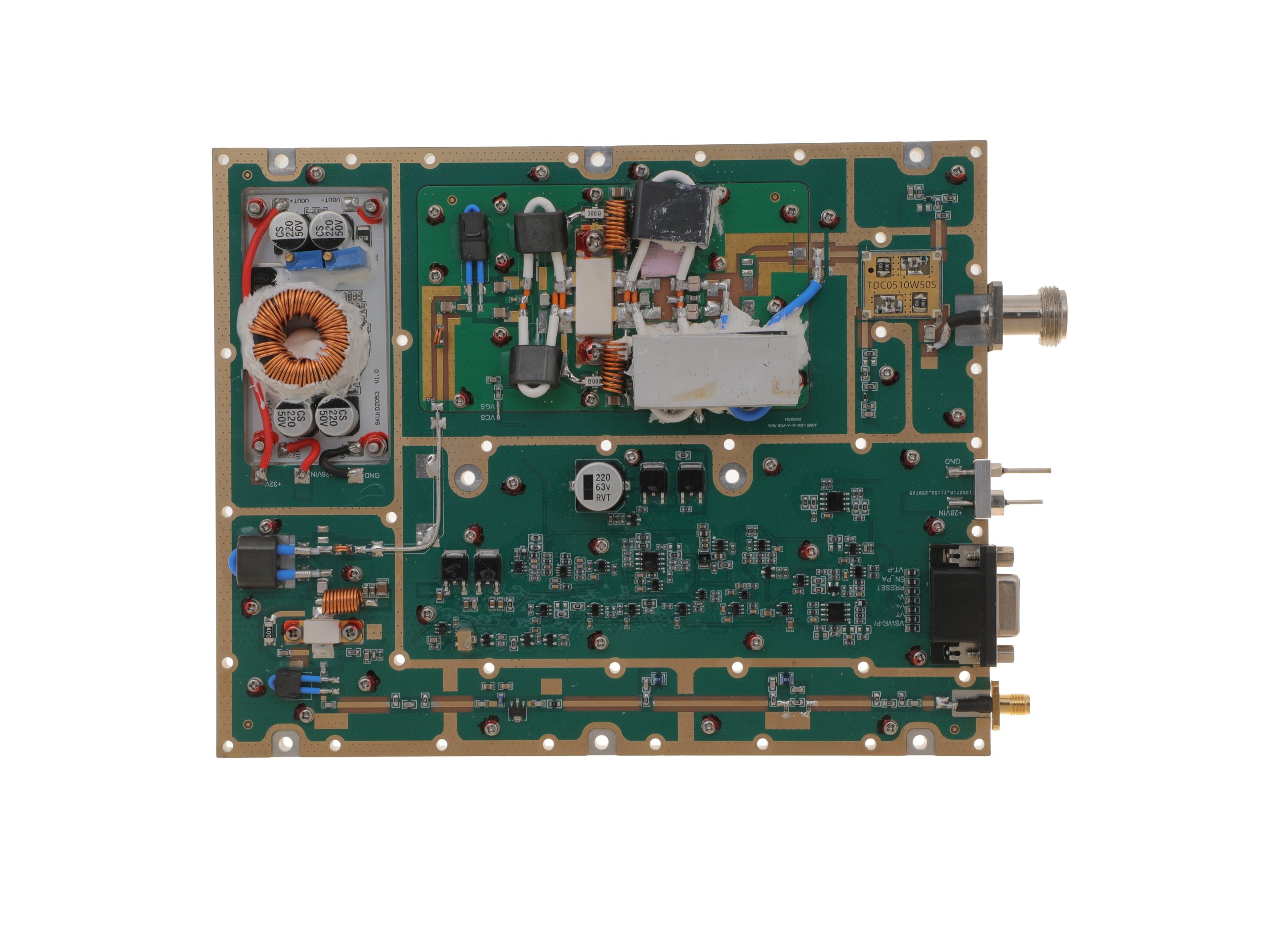 HZ30512-200NA1Open English PDF ↗ | 160 / 200 W | 29 / 36 A | 200 × 158 × 25 mmWeight: 1.4 kg | SMA-F / N-F | 15-pin D-Sub |
300–1200 MHz · 5 standard models
| Power | Model / PDF | Psat min. / typ. | Current typ. / max. | Dimensions | RF input / output | Control |
|---|---|---|---|---|---|---|
| 30 W | 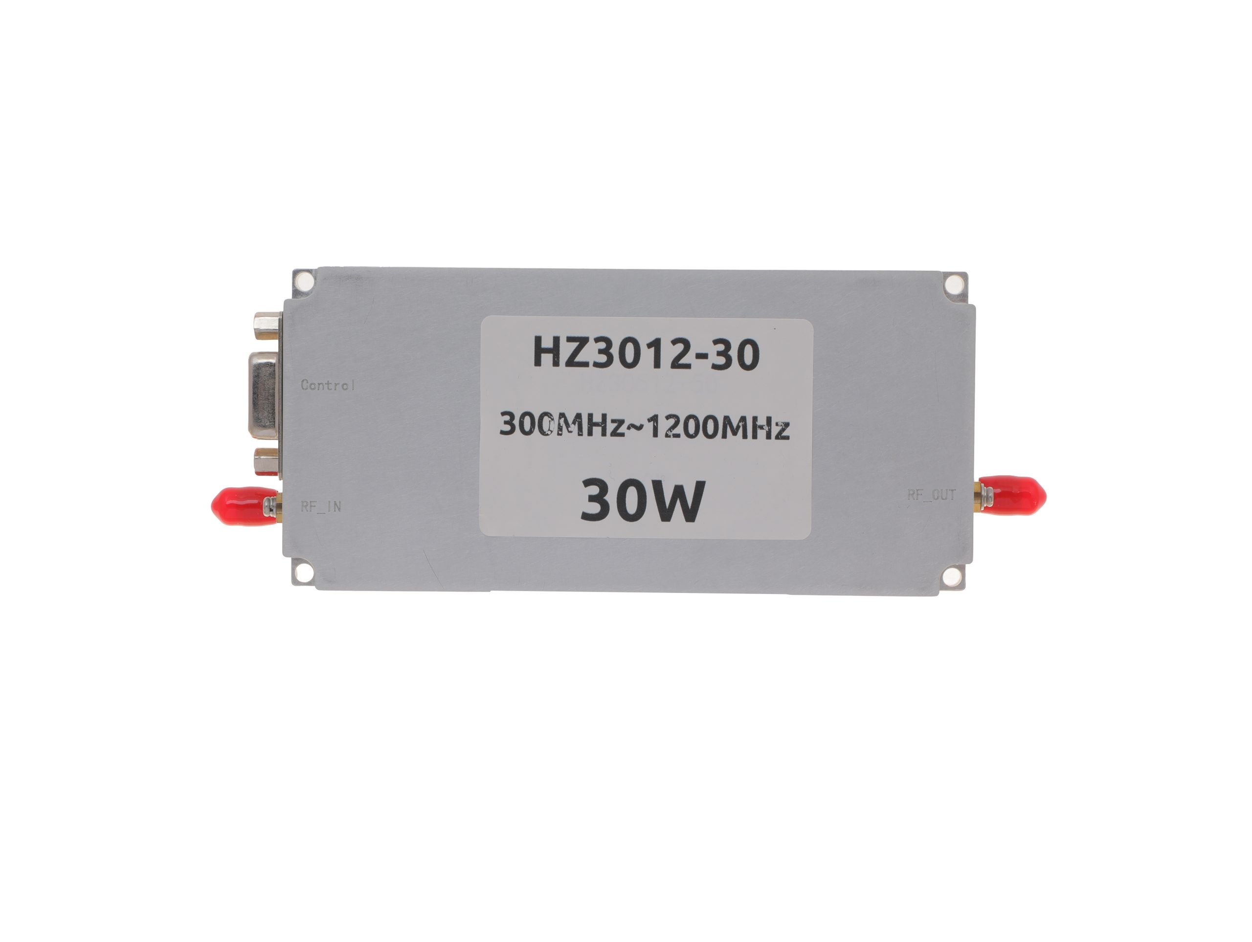 HZ3001200-30Open English PDF ↗ | 25 / 30 W | 2.4 / 3 A | 125 × 59 × 21.5 mm | SMA-KFD46 / SMA-KFD46 | 9-pin D-Sub |
| 50 W | 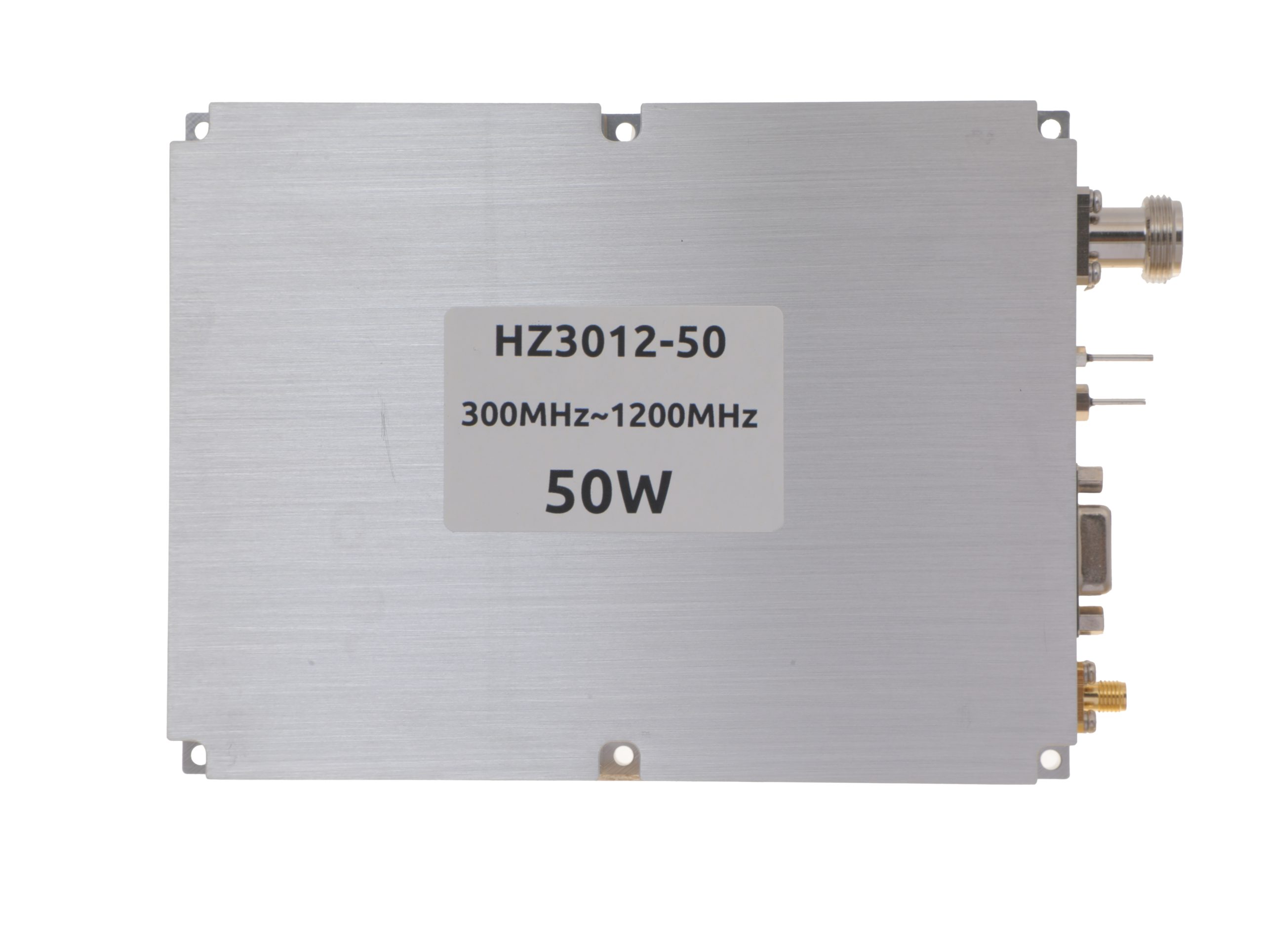 HZ3001200-50Open English PDF ↗ | 40 / 50 W | 5.6 / 7 A | 125 × 59 × 21.5 mm | SMA-KFD46 / SMA-KFD46 | 9-pin D-Sub |
| 100 W | 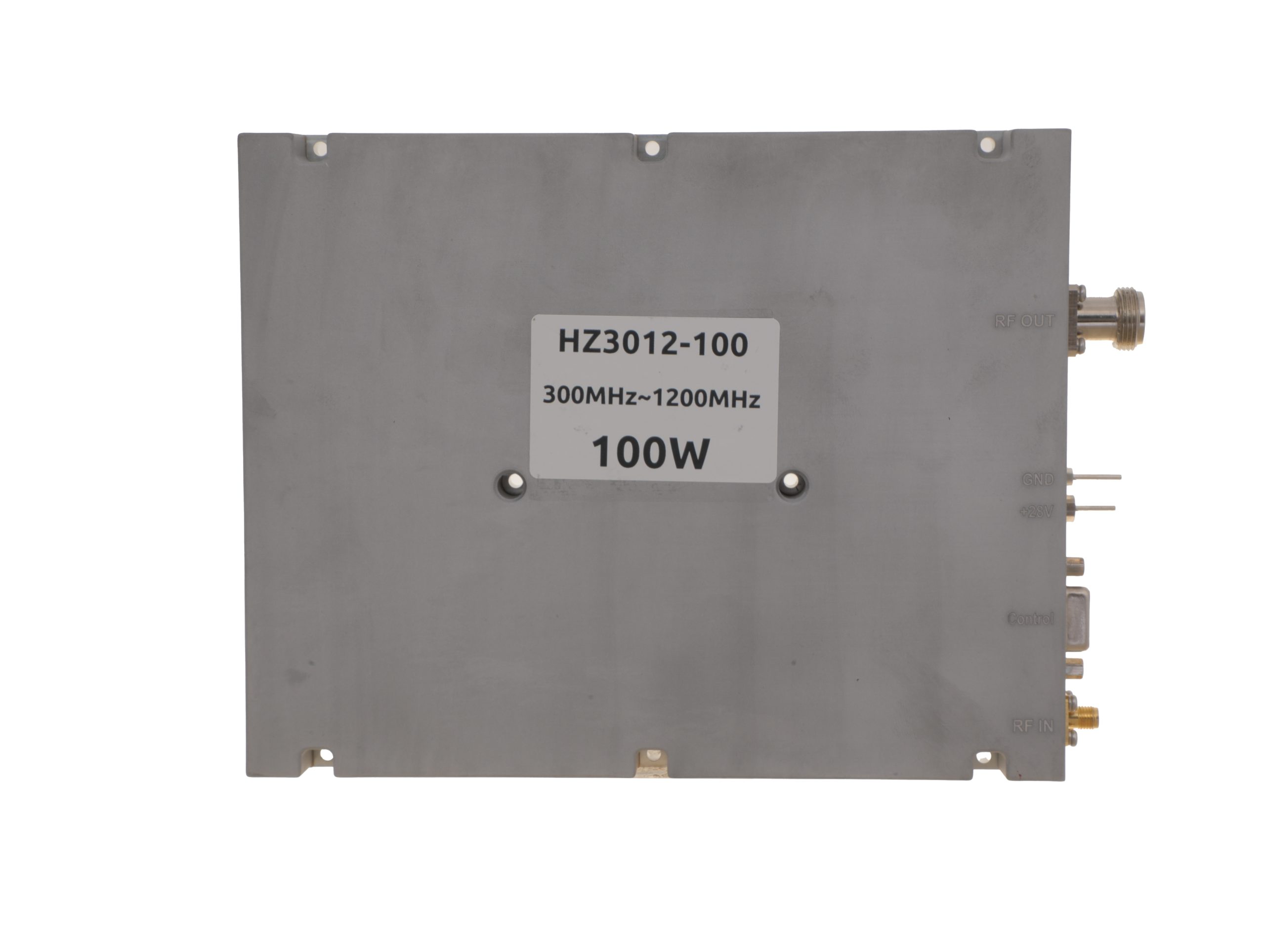 HZ3001200-100Open English PDF ↗ | 80 / 100 W | 11.5 / 14 A | 200 × 158 × 25 mm | SMA-F / N-F | 15-pin D-Sub |
| 150 W | 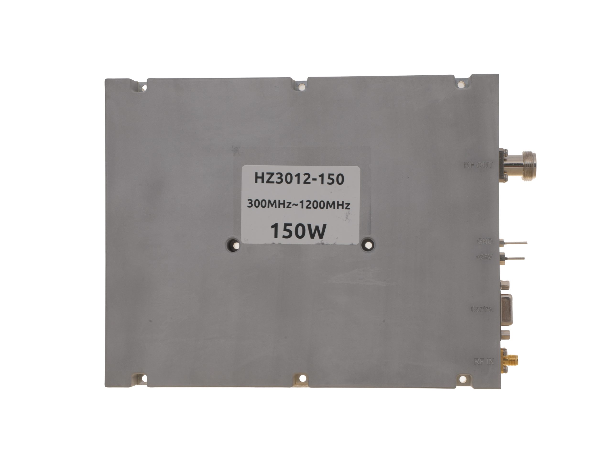 HZ3001200-150Open English PDF ↗ | 120 / 150 W | 18 / 22 A | 200 × 158 × 25 mm | SMA-F / N-F | 15-pin D-Sub |
| 200 W | 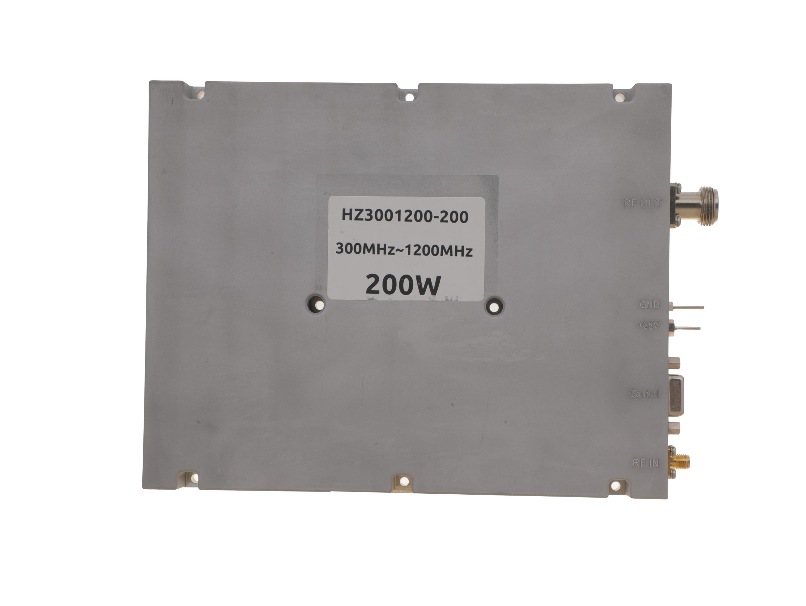 HZ3001200-200Open English PDF ↗ | 160 / 200 W | 24 / 29 A | 200 × 158 × 25 mm | SMA-F / N-F | 15-pin D-Sub |
300–1700 MHz · 5 standard models
| Power | Model / PDF | Psat min. / typ. | Current typ. / max. | Dimensions | RF input / output | Control |
|---|---|---|---|---|---|---|
| 30 W | 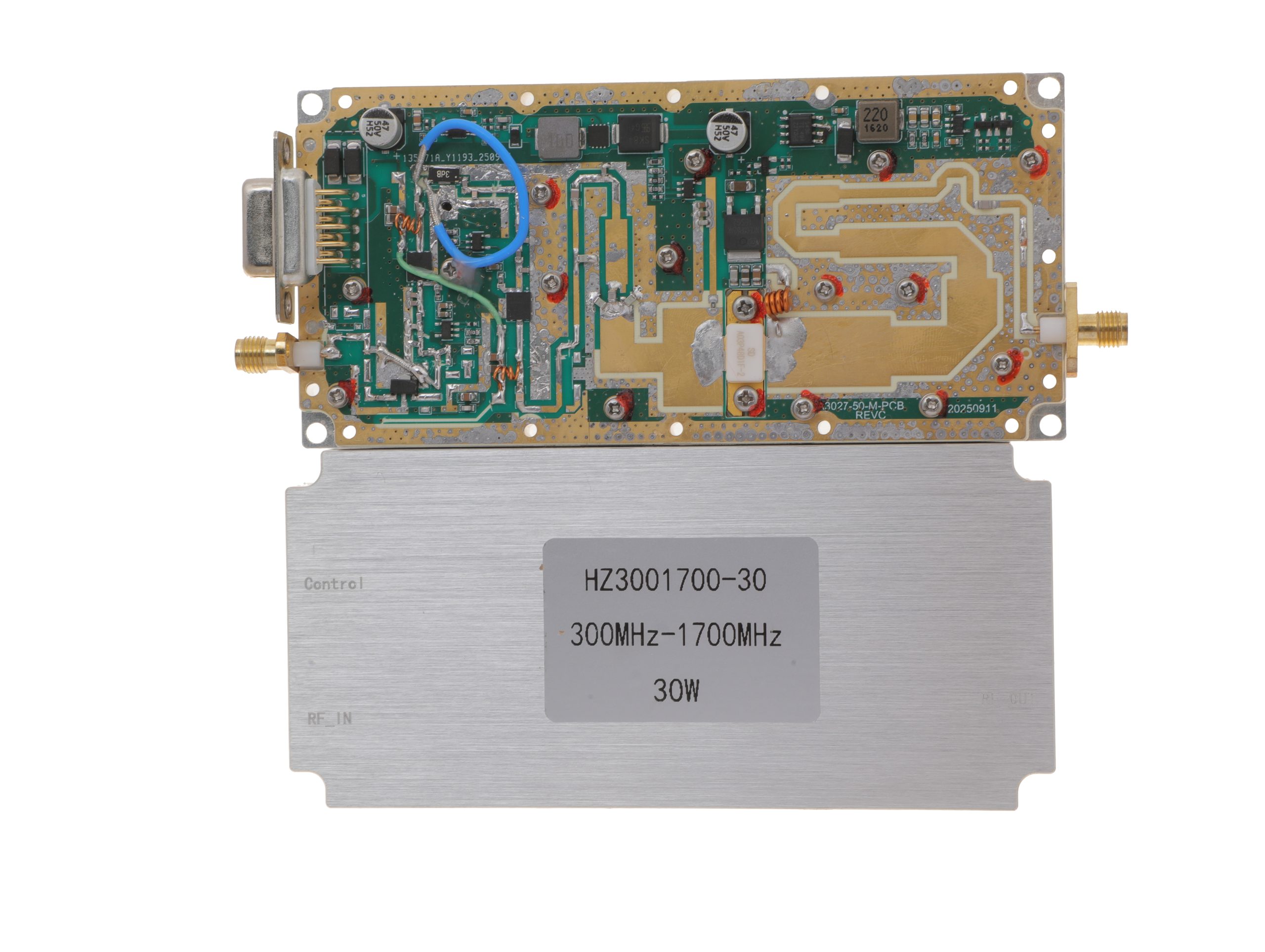 HZ3001700-30Open English PDF ↗ | 25 / 30 W | 2.4 / 3 A | 125 × 59 × 21.5 mm | SMA-KFD46 / SMA-KFD46 | 9-pin D-Sub |
| 50 W | 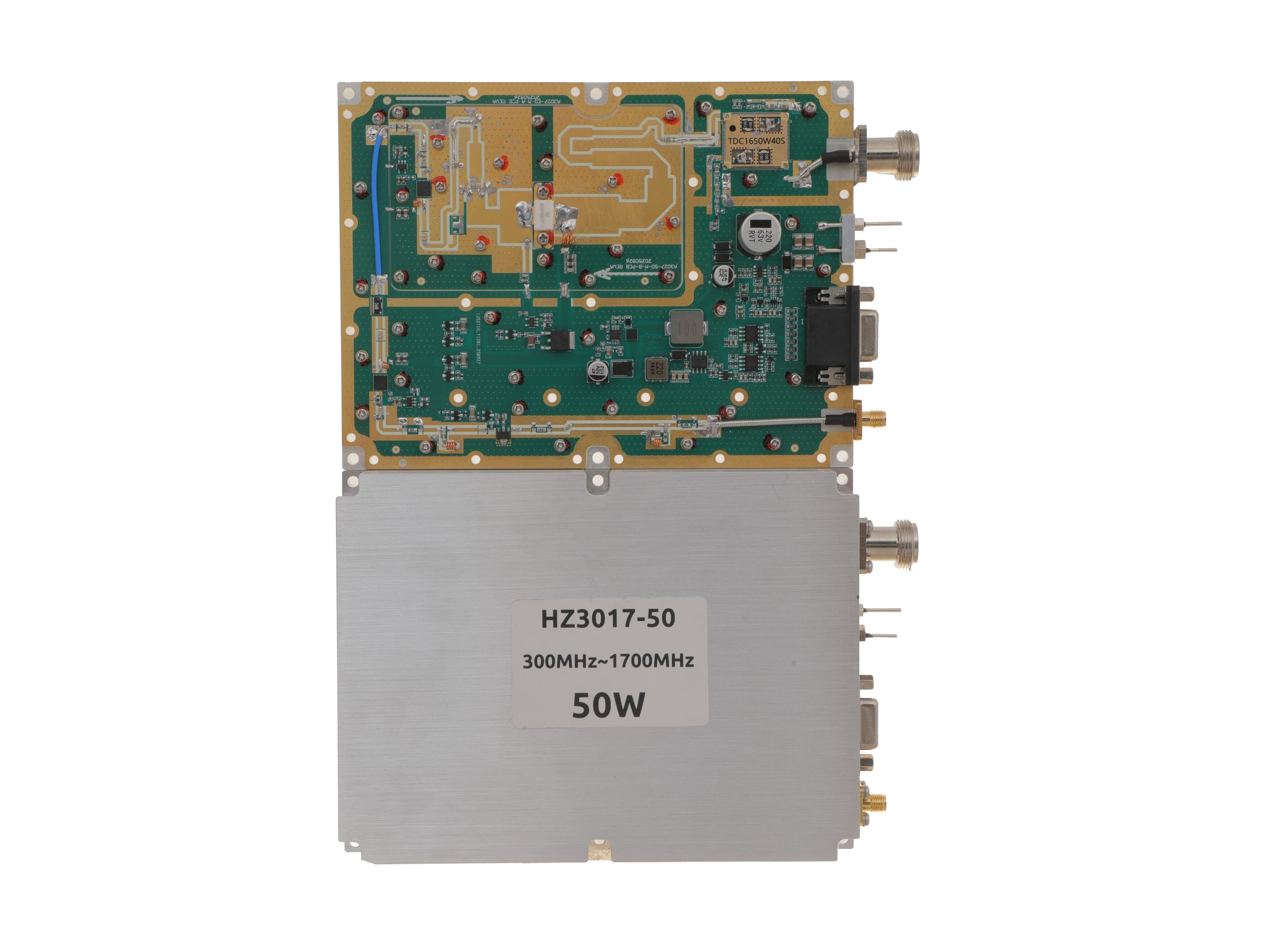 HZ3001700-50Open English PDF ↗ | 40 / 50 W | 5.6 / 7 A | 160 × 120 × 25 mm | SMA-F / N-F | 15-pin D-Sub |
| 100 W | 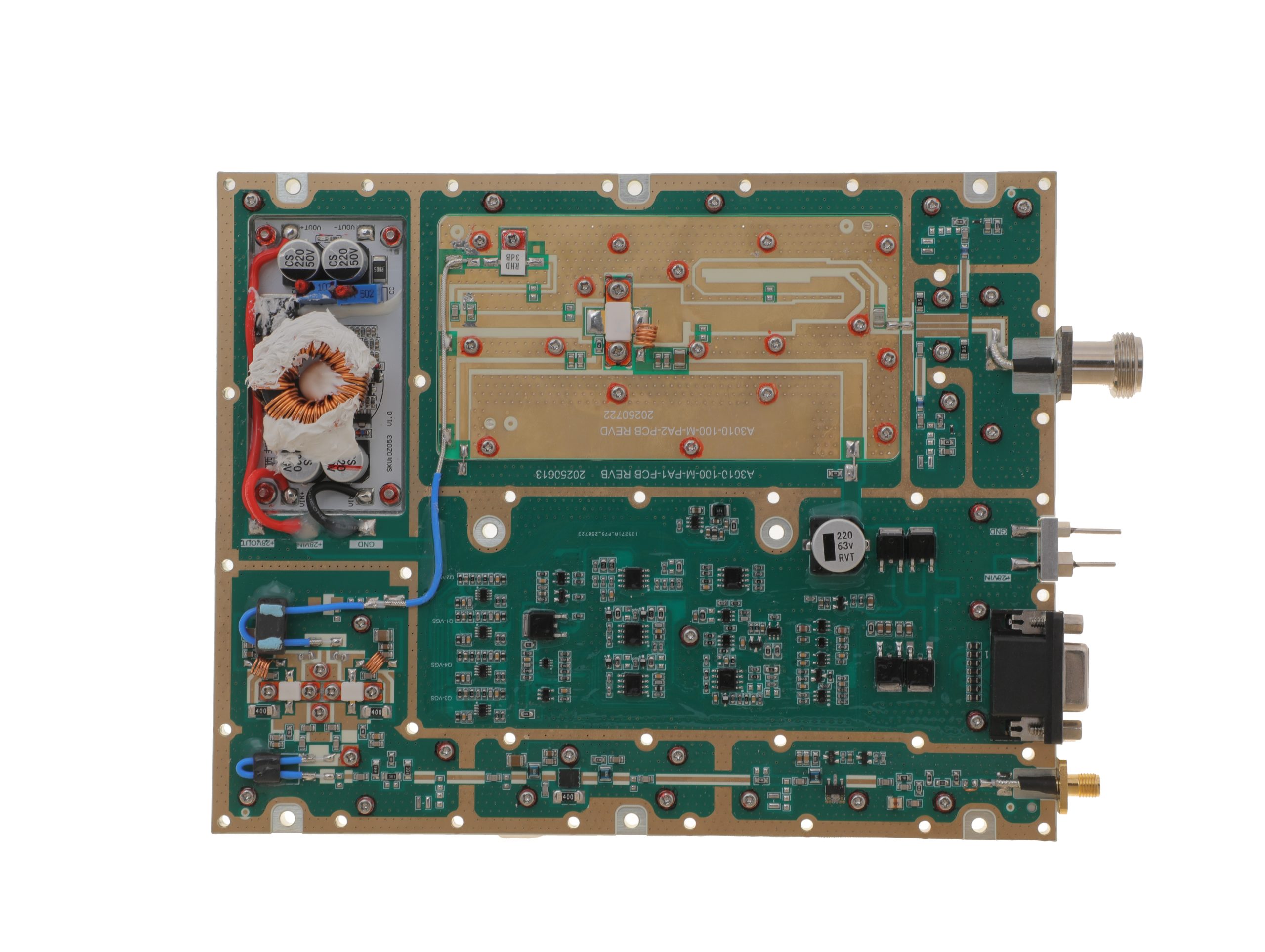 HZ3001700-100Open English PDF ↗ | 80 / 100 W | 11.5 / 14 A | 200 × 158 × 25 mm | SMA-F / N-F | 15-pin D-Sub |
| 150 W | 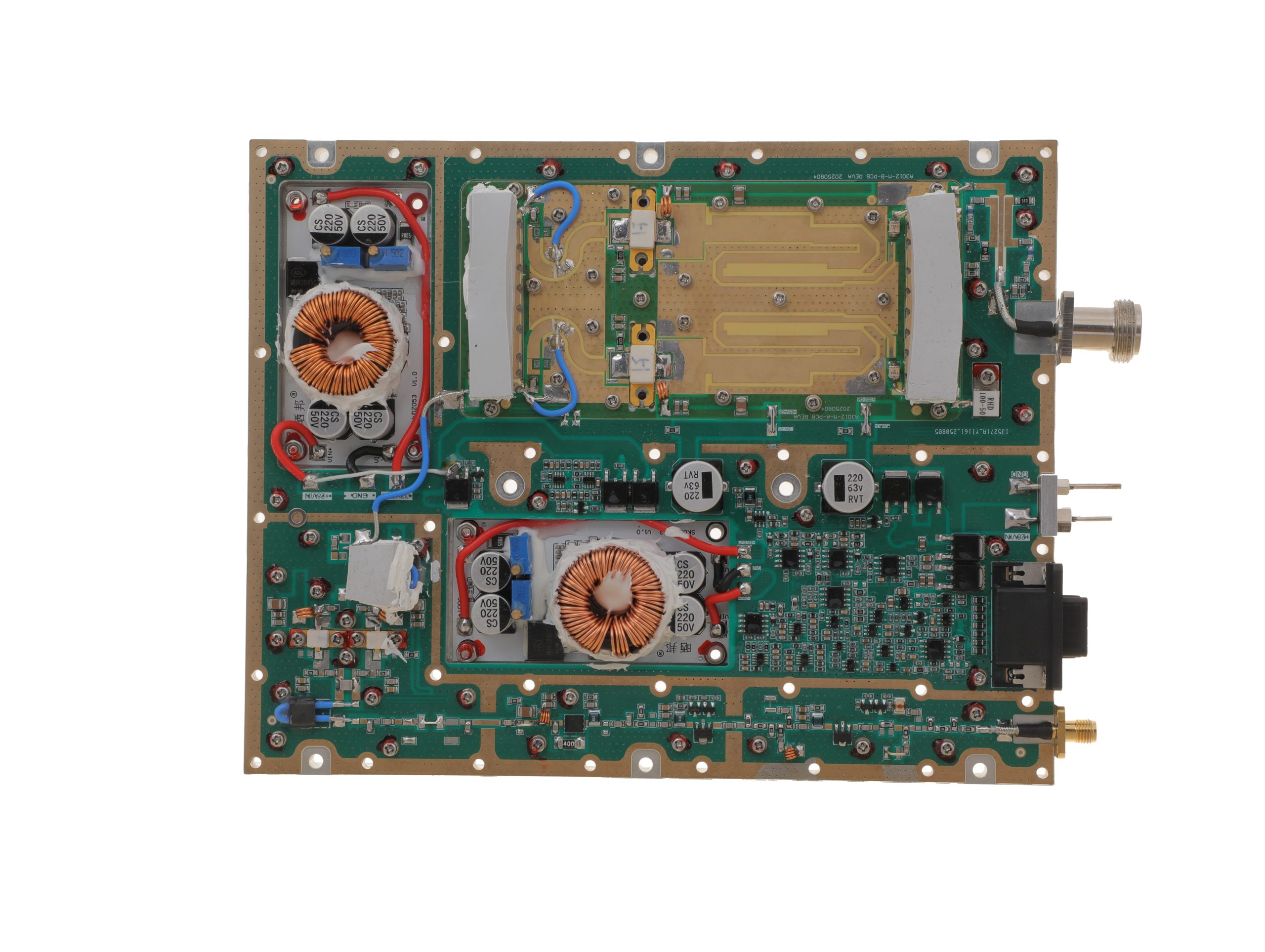 HZ3001700-150Open English PDF ↗ | 120 / 150 W | 18 / 22 A | 200 × 158 × 25 mm | SMA-F / N-F | 15-pin D-Sub |
| 200 W | 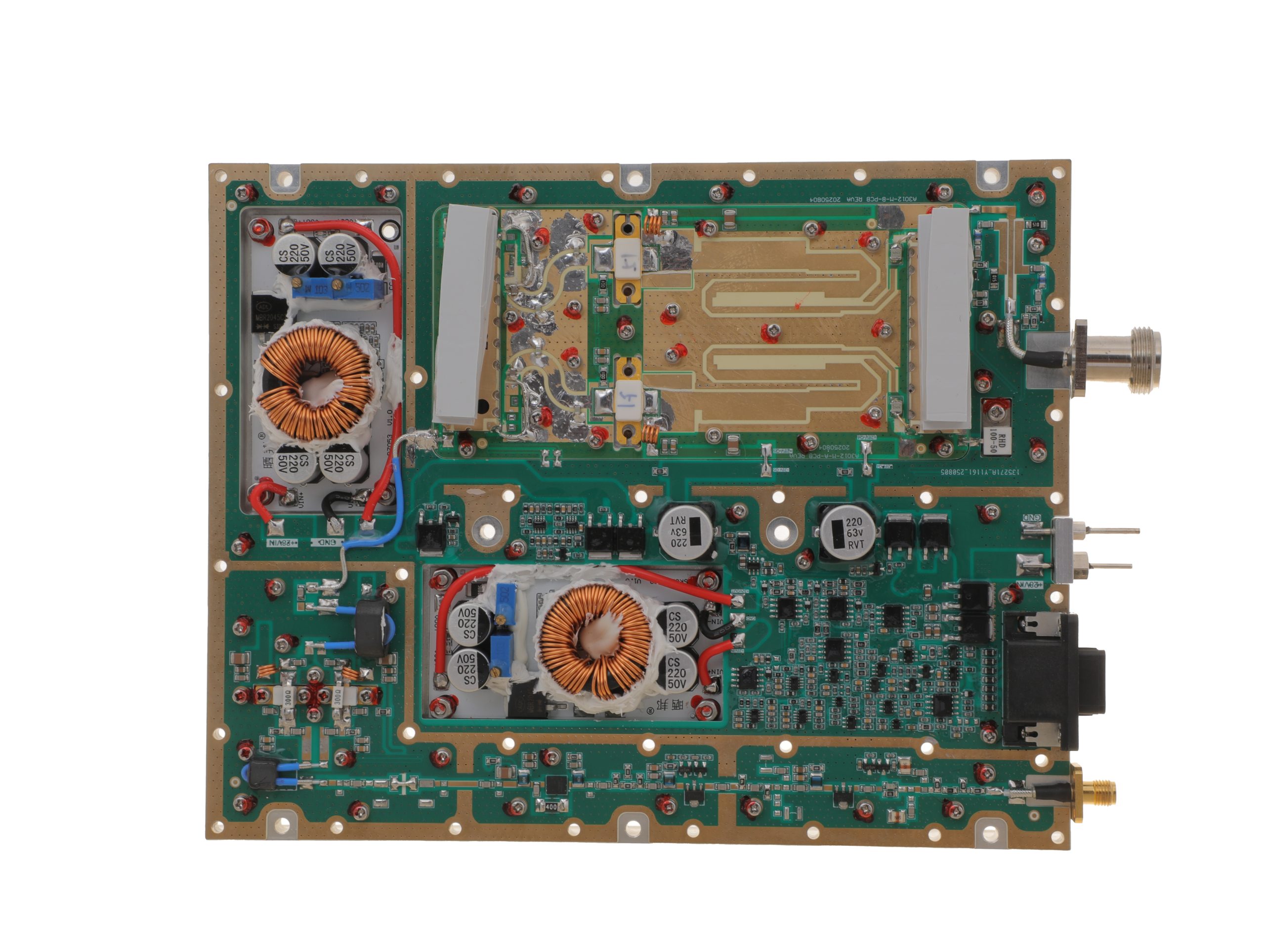 HZ3001700-200Open English PDF ↗ | 158 / 200 W | 24 / 29 A | 200 × 158 × 25 mm | SMA-F / N-F | 15-pin D-Sub |
300–2700 MHz · 5 standard models
| Power | Model / PDF | Psat min. / typ. | Current typ. / max. | Dimensions | RF input / output | Control |
|---|---|---|---|---|---|---|
| 30 W | 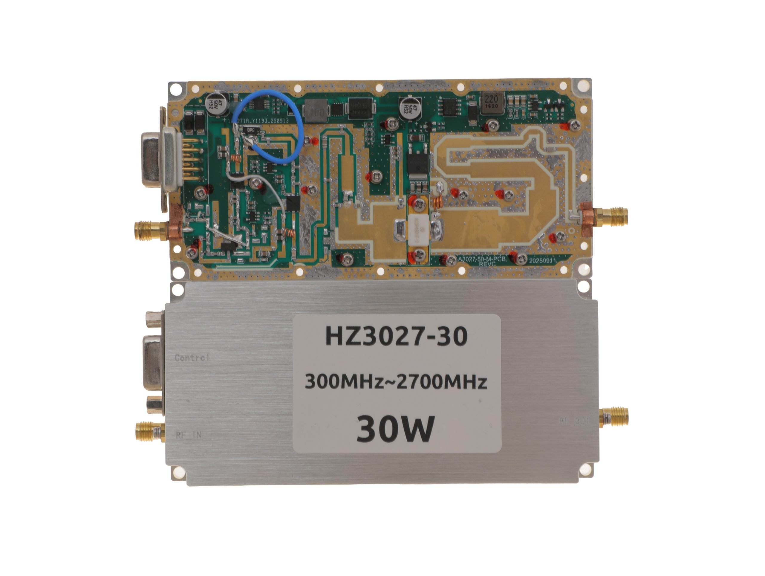 HZ3002700-30NA1Open English PDF ↗ | 25 / 30 W | 3.2 / 4 A | 125 × 59 × 21.5 mm | SMA-KFD46 / SMA-KFD46 | 9-pin D-Sub |
| 50 W | 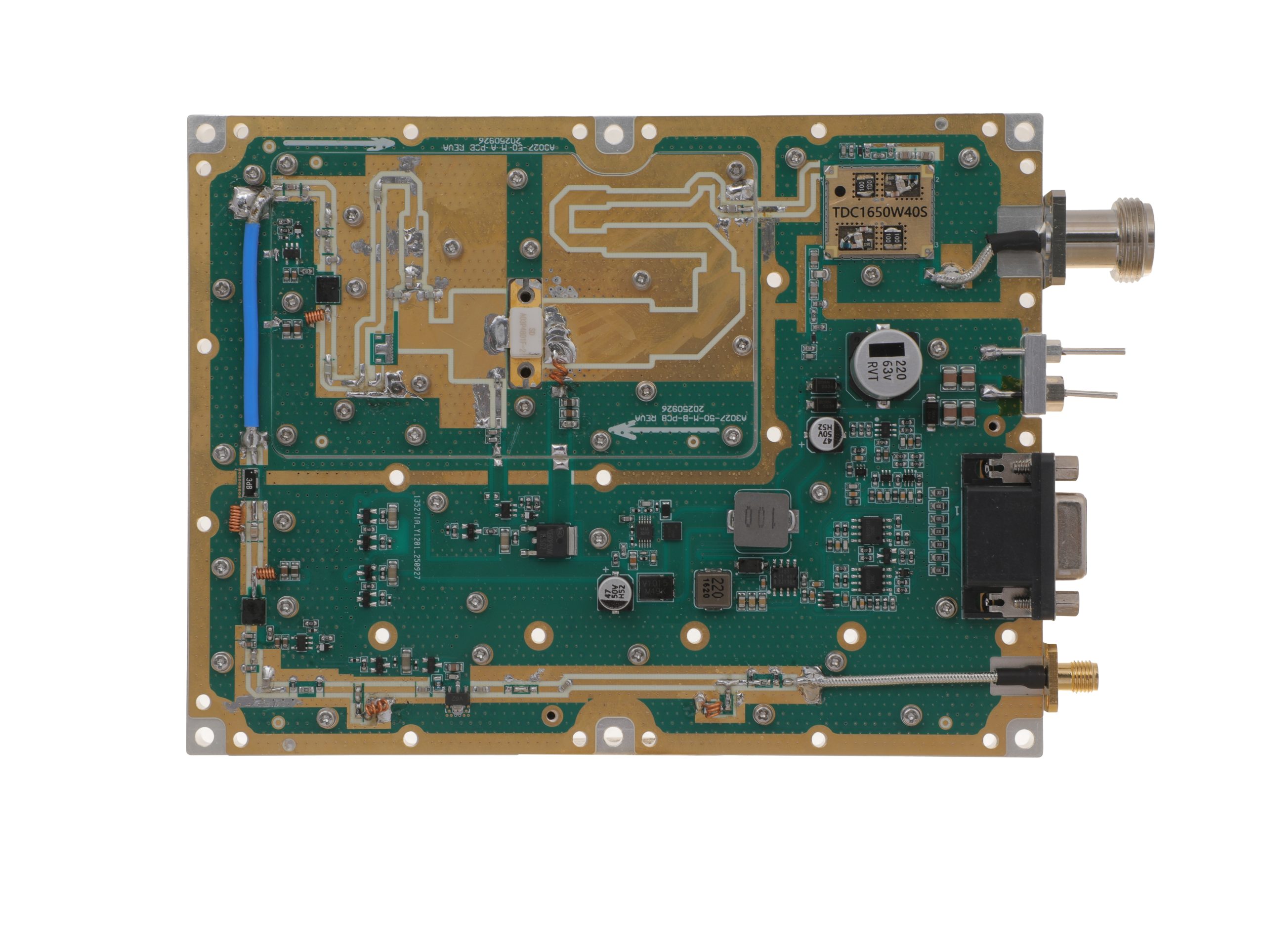 HZ3002700-50NA1Open English PDF ↗ | 40 / 50 W | 7.2 / 9 A | 160 × 120 × 25 mm | SMA-F / N-F | 15-pin D-Sub |
| 100 W | 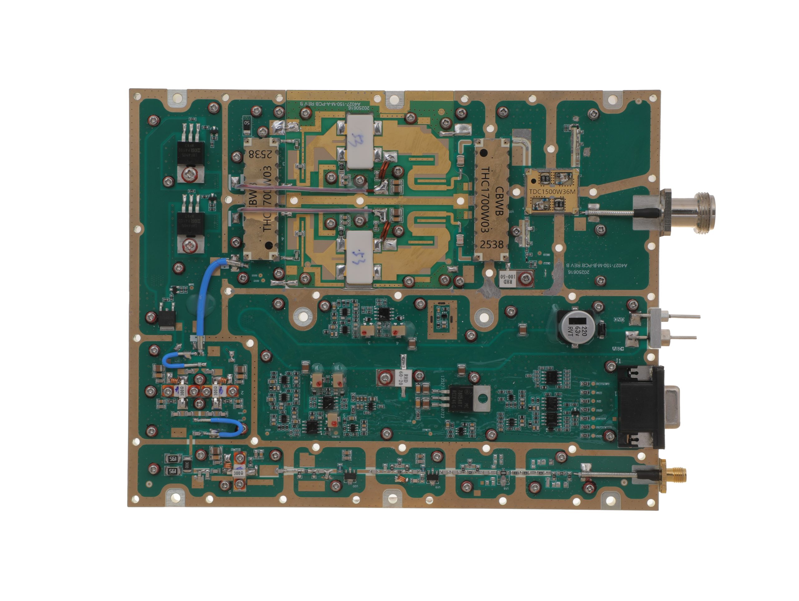 HZ3002700-100NA1Open English PDF ↗ | 80 / 100 W | 14.5 / 18 A | 200 × 158 × 25 mm | SMA-F / N-F | 15-pin D-Sub |
| 150 W | 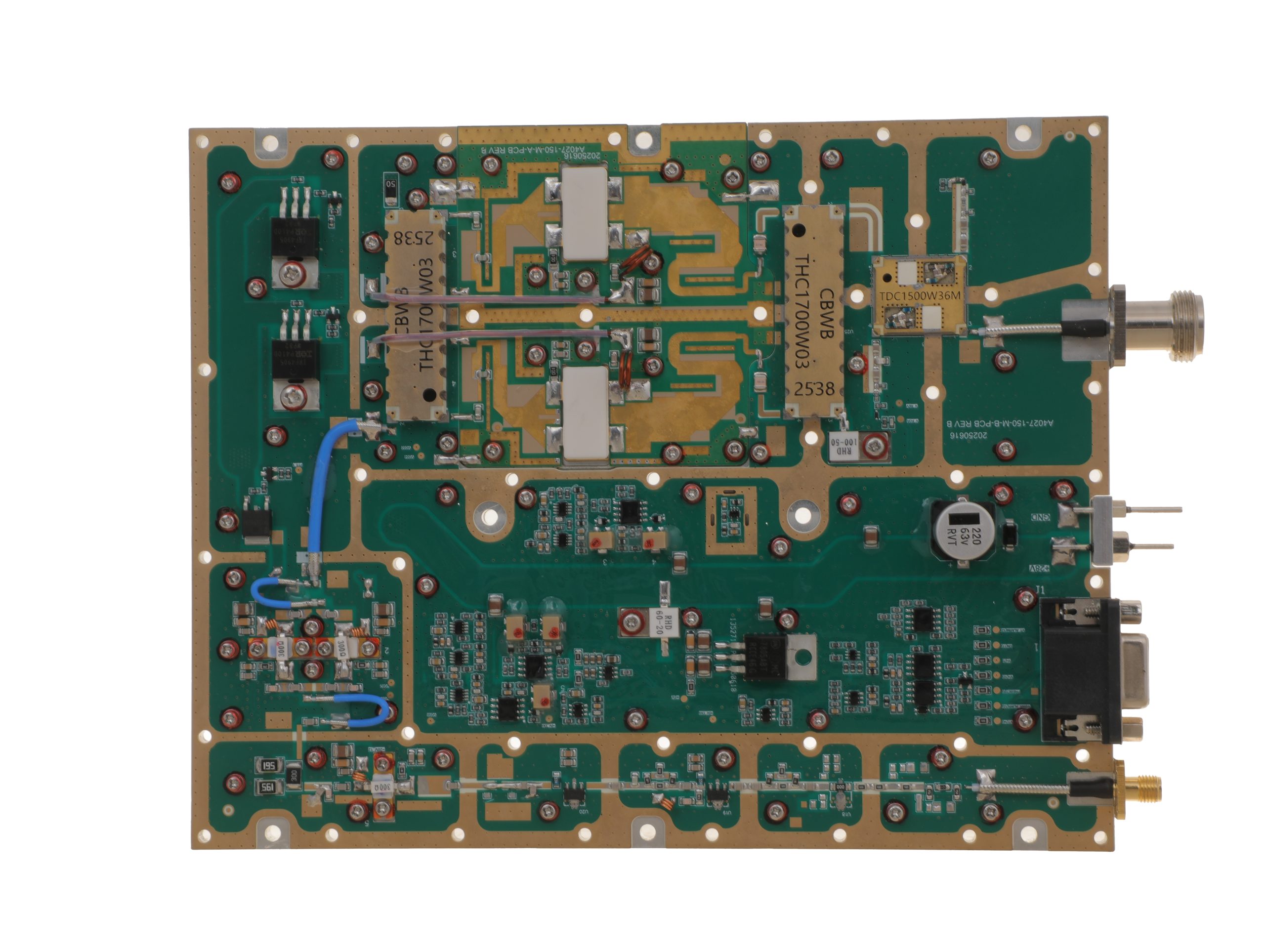 HZ3002700-150NA1Open English PDF ↗ | 120 / 150 W | 16 / 20 A | 200 × 158 × 25 mm | SMA-F / N-F | 15-pin D-Sub |
| 200 W | 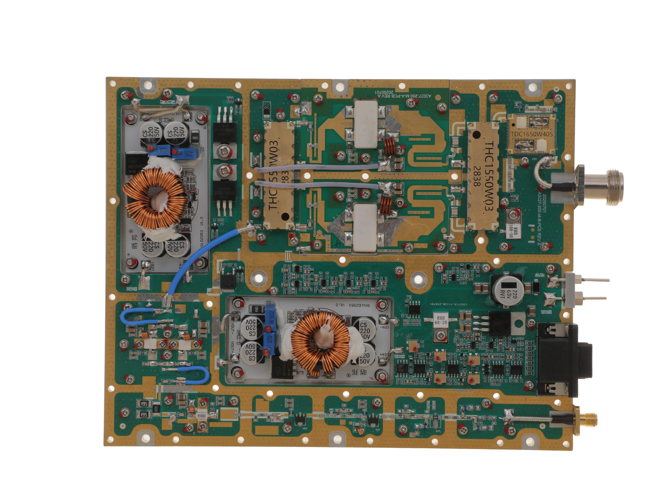 HZ3002700-200NA1Open English PDF ↗ | 160 / 200 W | 29 / 36 A | 200 × 158 × 25 mm | SMA-F / N-F | 15-pin D-Sub |
2000–6000 MHz · 5 standard models
| Power | Model / PDF | Psat min. / typ. | Current typ. / max. | Dimensions | RF input / output | Control |
|---|---|---|---|---|---|---|
| 30 W | 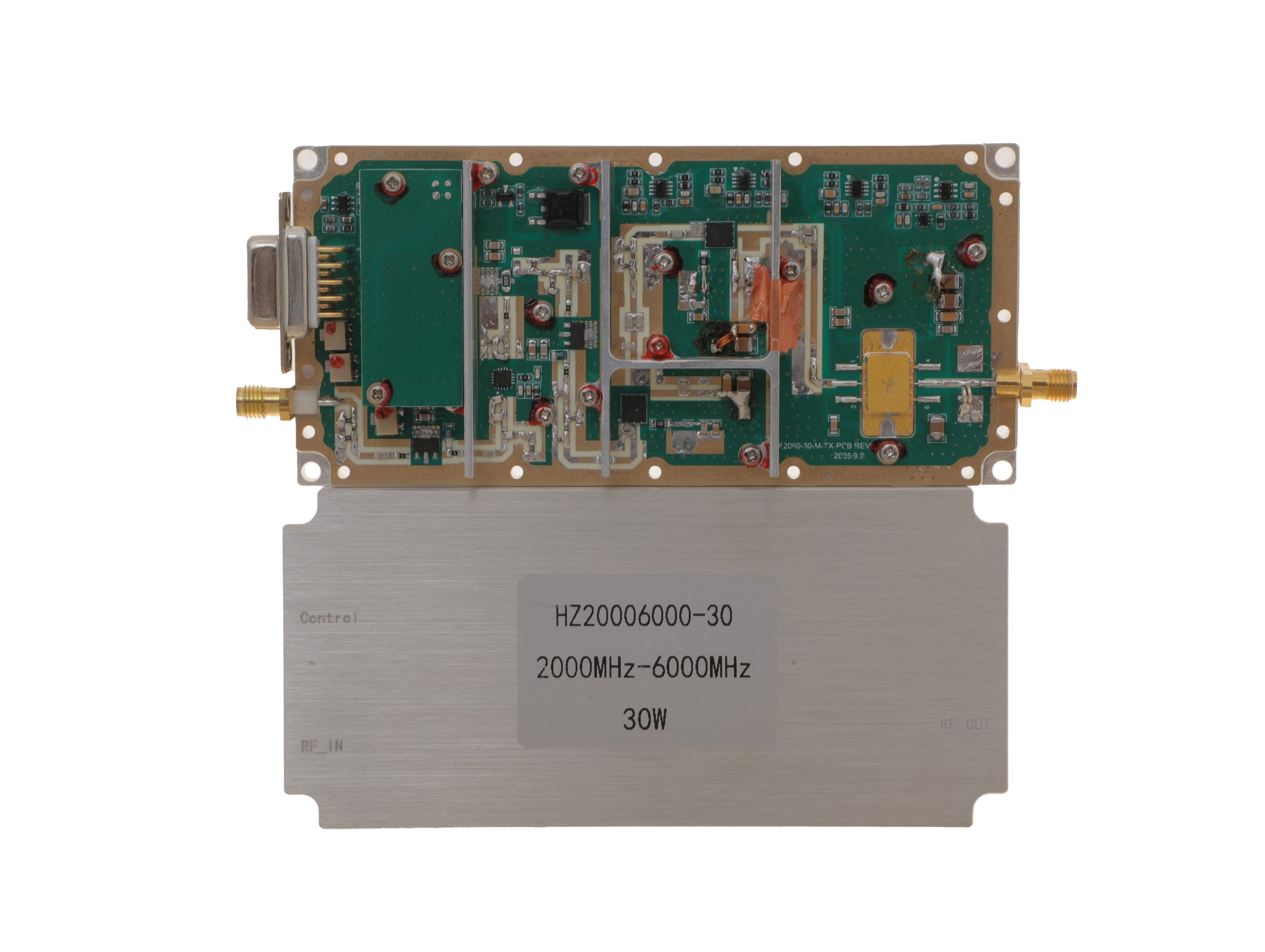 HZ20006000-30NA1Open English PDF ↗ | 25 / 30 W | 3.2 / 4 A | 125 × 59 × 21.5 mm | SMA-KFD46 / SMA-KFD46 | 9-pin D-Sub |
| 50 W | 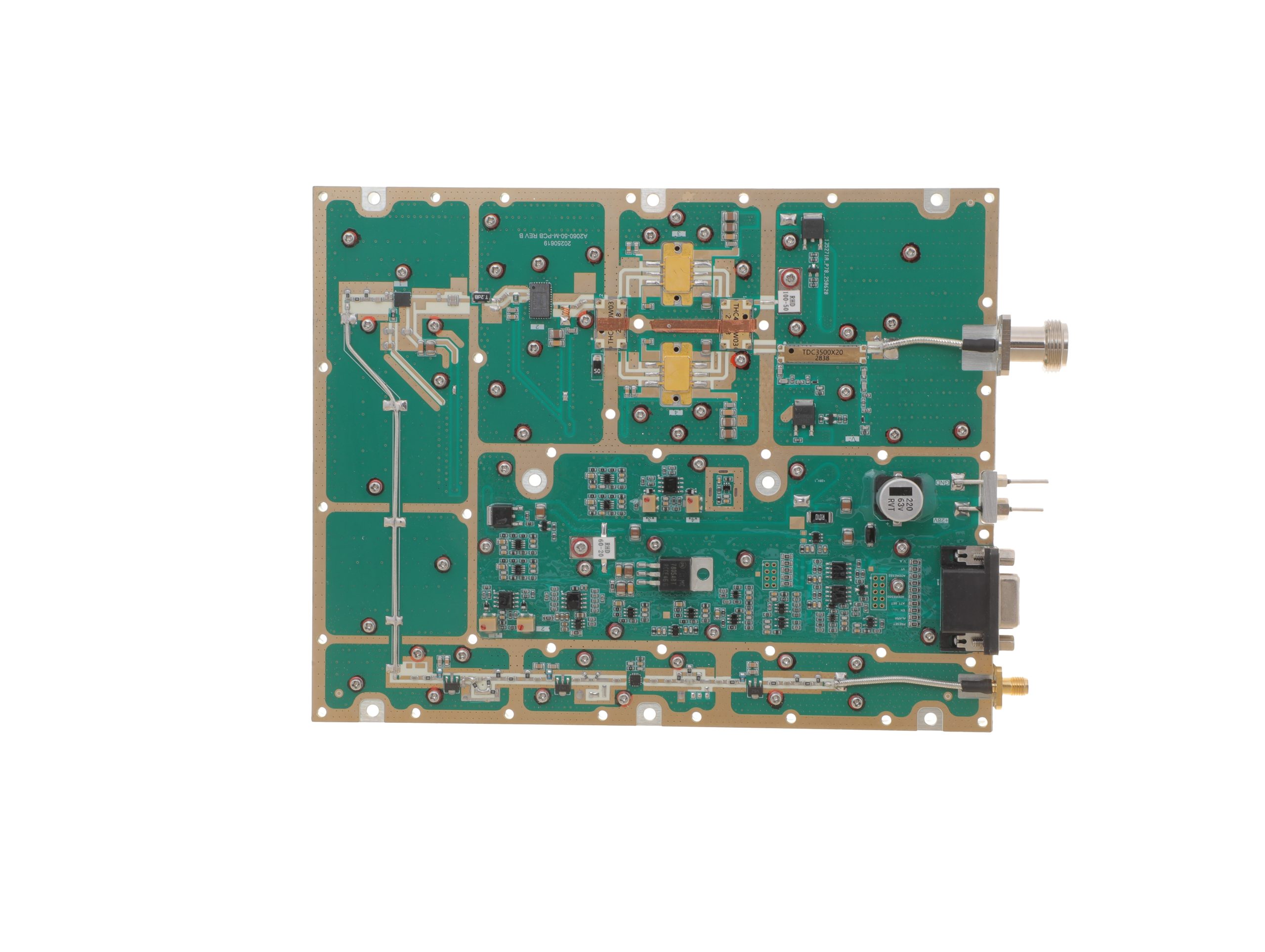 HZ20006000-50NA1Open English PDF ↗ | 40 / 50 W | 10 / 12 A | 200 × 158 × 25 mm | SMA-F / N-F | 15-pin D-Sub |
| 100 W | 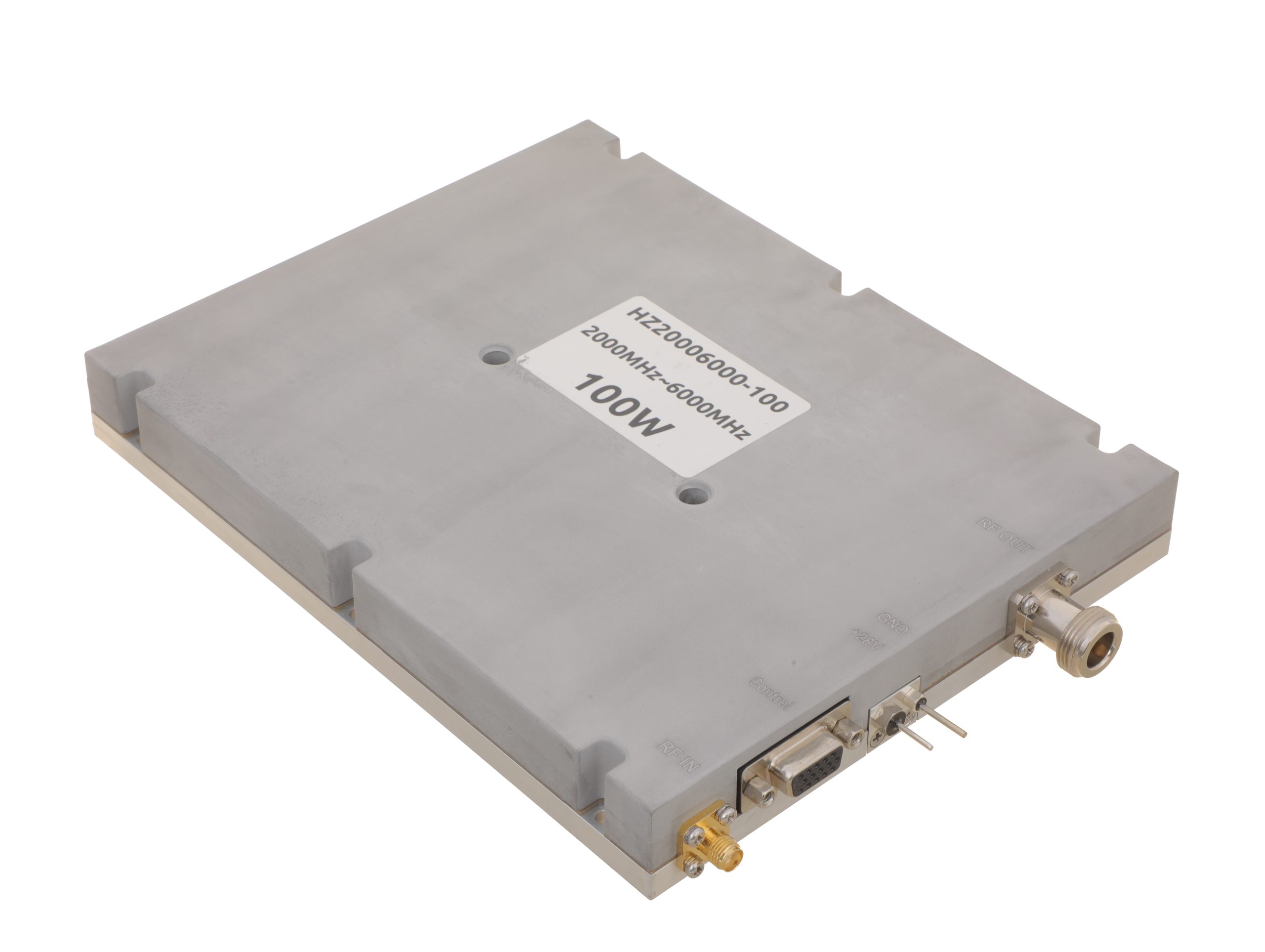 HZ20006000-100NA1Open English PDF ↗ | 80 / 100 W | 19 / 24 A | 200 × 158 × 25 mm | SMA-F / N-F | 15-pin D-Sub |
| 150 W | 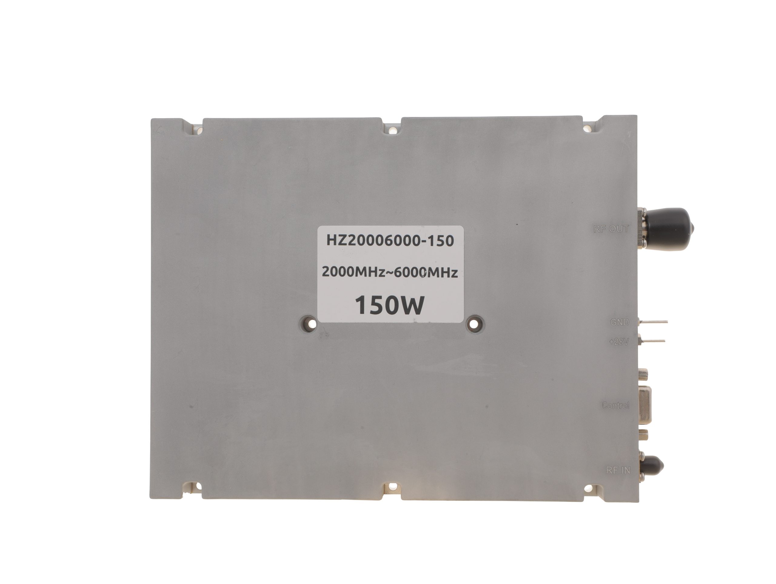 HZ20006000-150NA1Open English PDF ↗ | 120 / 150 W | 22 / 27 A | 200 × 158 × 25 mm | SMA-F / N-F | 15-pin D-Sub |
| 200 W | 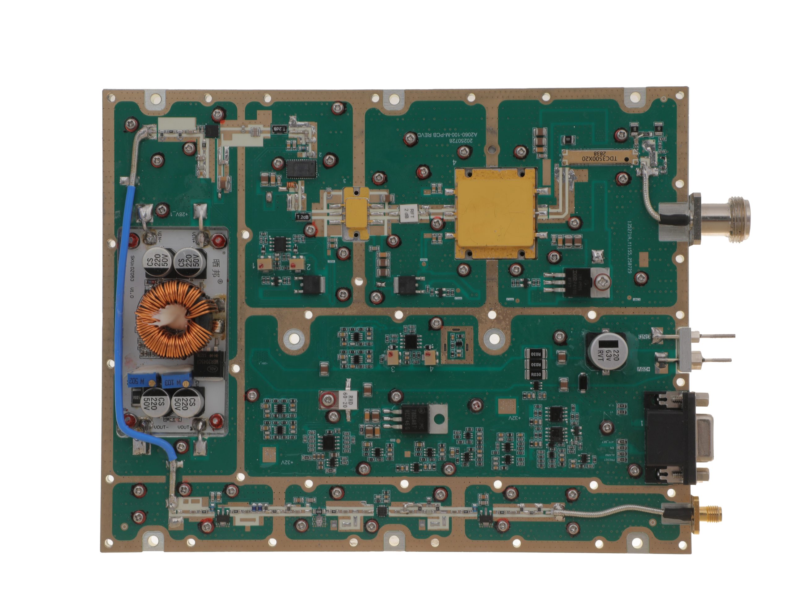 HZ20006000-200NA1Open English PDF ↗ | 160 / 200 W | 29 / 36 A | 280 × 250 × 25 mm | SMA-F / N-F | 15-pin D-Sub |
Review the applicable model’s English PDF datasheet for RF input drive, protection, and optional-function details.
Record whether the proposed harness remains compatible with the ordered configuration. Where documents conflict, obtain a supplier resolution or controlled statement of equivalence. Hold release if an interface-affecting revision cannot be matched to the proposed drawing.
7. What Evidence Is Required Before Releasing the D-Sub Harness Drawing?
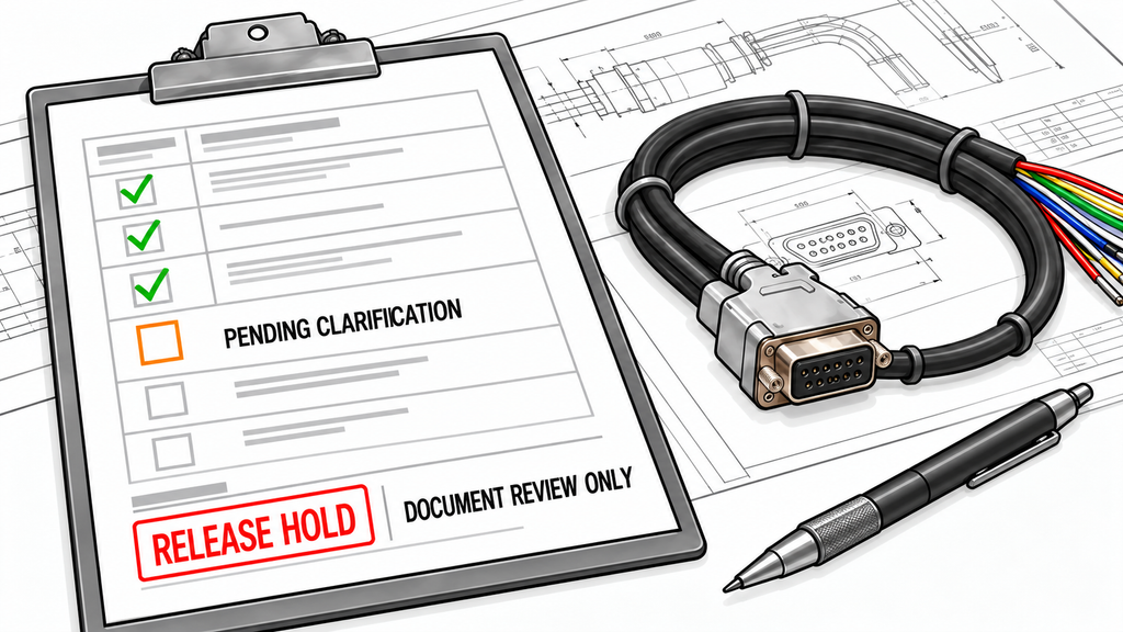
Keep the supplier’s interface definition, the matching harness drawing, and the supporting approval evidence together. Depending on the configuration, this package may include the interface-control specification, numbered connector views, approved mating-component information, electrical definitions, option confirmation, harness connection schedule, and revision records.
Retain written resolutions of drawing ambiguities. A verbal clarification should not be the only evidence supporting a released connection.
The D-Sub Harness Drawing Release Matrix below is a buyer-side review template. Its pending entries identify information to verify.
| Review Item | Supplier Document or Definition Required | Applicable Model / Configuration / Revision | Buyer Verification | Hold Condition | Review Status / Open Clarification |
|---|---|---|---|---|---|
| Connector and mating hardware | Approved connector views, mating-part identification, contact arrangement, and mounting requirements | Fitted connector and applicable mechanical drawing revision | Match contact count, gender, pin-view orientation, mating parts, and retention hardware | Connector identity or physical mating arrangement is ambiguous | Pending: identify approved component references |
| End-to-end harness mapping | Controlled pin assignment and harness conductor-to-terminal drawing | PA interface revision and harness drawing revision | Trace each populated PA contact through its wire identifier to the destination contact; check returns, shields, and unconnected pins | Any connection lacks a unique source, conductor, or destination | Pending: complete connection trace |
| Supply and return connections | Defined supply pins, returns, current requirements, and applicable contact limits | Ordered model and power-interface configuration | Verify all specified supply and return paths, contact ratings, and intended wiring | Current-carrying assignments or contact requirements are inferred | Pending: confirm power wiring |
| Control-input connections | Input direction, accepted levels, loading, polarity, and open-circuit behavior | Applicable control-interface revision | Compare controller output conditions with PA input requirements, including disconnected states | Input compatibility or required biasing is unresolved | Pending: confirm input implementation |
| Status, alarm, and analog connections | Output type, active state, loading limits, reference, and scaling where applicable | Functions provided by the ordered configuration | Verify destination input compatibility and the documented meaning of each connected output | Output characteristics or electrical reference are unspecified | Pending: confirm output wiring |
| Default, fault, and reset behavior | Applicable startup, power-off, disconnected, fault, and reset-contact definitions | Actual model and relevant control revision | Confirm the harness connection supports the required electrical states, including controller power-loss conditions where applicable | The proposed wiring depends on an undocumented default or reset state | Pending: resolve state conditions |
| Optional and communication functions | Option-specific pinout and physical communication-interface requirements | Exact option suffix and relevant hardware or firmware revision | Verify that each wired optional function is fitted and that communication contacts are correctly assigned | Any connection depends on an unconfirmed option or interface assignment | Pending: confirm configuration |
| Revision and release authorization | Controlled interface documents, resolved change notices, and approved harness revision | Purchase configuration and all applicable document revisions | Record document consistency, remaining exceptions, designated reviewer, approval status, and date | A revision conflict or material clarification remains open | Pending: obtain controlled release approval |
Swipe horizontally to review all six release fields →
For each applicable row, record the supporting document revision and close outstanding clarifications. For a not-applicable entry, record why the requirement does not apply to the ordered configuration.
The designated drawing-release authority should approve the final revision only after the required information agrees and unresolved issues are closed. Record who authorized release and when. Review later changes to connector assignments, electrical conditions, or fitted options under the project’s change-control process.
A completed document review supports manufacturing the harness against the approved interface drawing. It does not prove correct continuity, insulation, termination quality, current capacity, or functional behavior in the finished assembly. Those outcomes require the relevant physical inspection and verification after assembly.
Conclusion
Release the D-Sub interface portion of the harness drawing only when the correct connector and pin view, end-to-end wiring, electrical compatibility, options, and revisions agree with the documented requirements for the ordered amplifier. Unresolved interface assumptions require a release hold; they do not establish a product failure.
This review can determine whether the interface is documented well enough for drawing release. Model- and project-specific electrical limits still require formal evidence. Complete-system suitability, other manufacturing requirements, and finished-harness acceptance remain separate decisions.
Before requesting approval, mark every unresolved connection on the proposed drawing and reconcile it against the supplier’s controlled interface documents. Retain the completed release record with the approved drawing revision.
For a model-specific RF SKYPOWER engineering review, provide the exact amplifier model and options, intended control functions, controller I/O levels, proposed mating connector and end-to-end harness drawing, required startup or disconnected states, and applicable document revisions. These inputs allow the interface requirements to be reviewed against the intended assembly before manufacturing authorization.