











An RF power amplifier harmonic test must cover the fundamental test points, harmonic orders, and operating conditions required by the approved acceptance plan. Each required combination needs usable measurement evidence. One spectrum capture cannot establish performance across an entire operating band.
The measurement path must work at the harmonic frequency and provide enough sensitivity to evaluate the applicable limit. Start with the required frequency–harmonic combinations, then check which records support them and what remains unresolved.
1. Why Is a Harmonic Result Incomplete Without a Defined Test Scope?
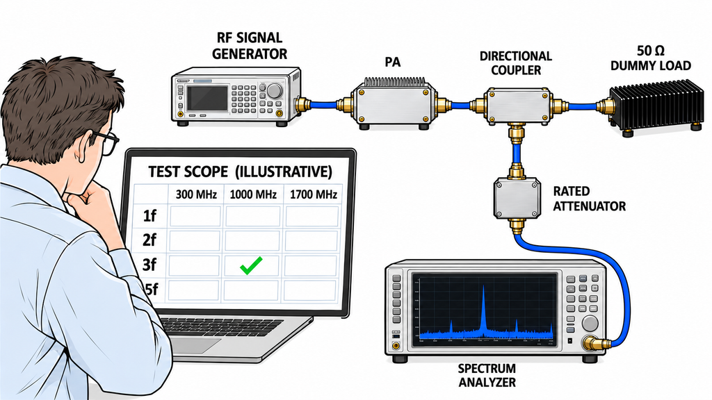
A harmonic result applies to the frequency and operating condition recorded with it. For a 300–1700 MHz PA, measurements at a 1000 MHz fundamental may show components at 2000 and 3000 MHz. They provide no direct evidence of second- or third-harmonic performance at fundamentals of 300 or 1700 MHz.
Before testing, identify the required fundamental points, harmonic orders, operating states, and acceptance requirements. A datasheet’s operating range specifies where the PA is intended to work; it does not define the harmonic test scope.
When comparing RF power amplifier modules, check the scope of their supporting reports as well as their nominal frequency ranges. Two reports may contain different test points, harmonic orders, or operating conditions.
Review the available results against the approved scope. Without that scope, the reviewer cannot identify missing measurements or confirm that the required testing is complete.
2. Which Harmonic Frequencies Follow Each Required PA Test Point?
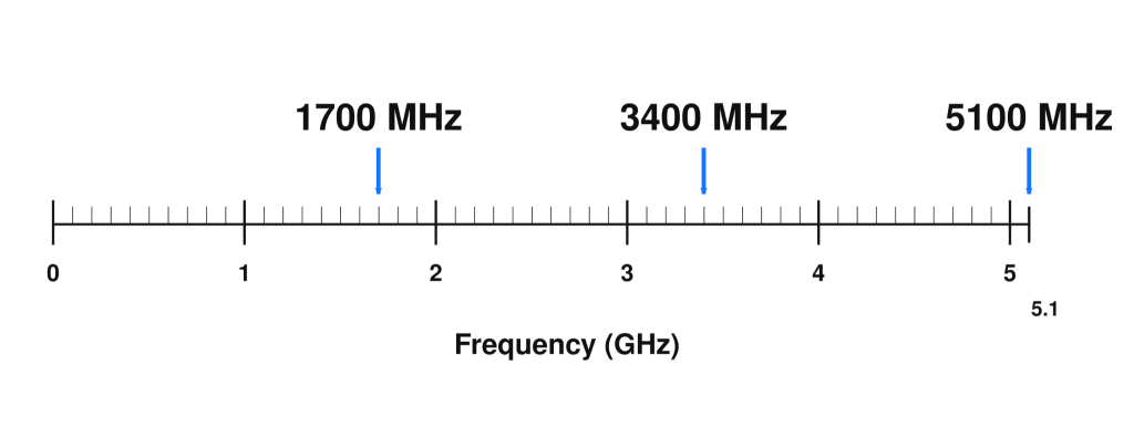
For a single-tone fundamental frequency f, the harmonic of order n occurs at nf: 2f for the second harmonic and 3f for the third.
Choose the fundamental test points before calculating these frequencies. If the project has no approved point list, propose points based on operating-band edges, required operating channels, changes in RF performance or filtering conditions, and project-specific worst-case frequencies identified during engineering review. These are candidates for approval, not a universal test grid. The responsible acceptance authority must confirm the required points and harmonic orders.
For an illustrative 300–1700 MHz operating range, suppose the selected fundamental points are 300, 1000, and 1700 MHz. At 300 MHz, the second and third harmonics are at 600 and 900 MHz. At 1000 MHz, they are at 2000 and 3000 MHz. At 1700 MHz, they are at 3400 and 5100 MHz.
If the project requires third-harmonic evidence at a 1700 MHz fundamental, the measurement system must support the observation at 5100 MHz.
For fundamentals spanning 300–1700 MHz, the corresponding second-harmonic locations span 600–3400 MHz, and third-harmonic locations span 900–5100 MHz. Whether testing requires a continuous sweep or selected points belongs in the approved plan. A swept-frequency record counts as valid harmonic evidence only where the procedure accounts for the required dwell, acquisition, operating state, and measurement method.
Results at selected points should not be extended to every untested frequency between them unless the approved method supports that conclusion.
The single-tone calculation also does not specify the measurement bandwidth for modulated or multitone signals. Their spectra can extend around harmonic centers and contain other nonlinear products. Define the required frequency spans, power metrics, and measurement methods for those waveforms separately.
The resulting point list should identify each required fundamental–harmonic combination and its measurement frequency or span under the specified test condition.
3. What If a Harmonic Falls Inside Another Operating Band?
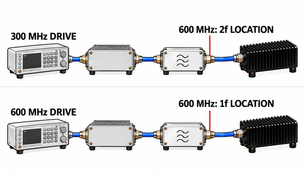
At a 300 MHz fundamental, the second and third harmonics of a 300–1700 MHz PA lie at 600 and 900 MHz, inside its operating range. During a 600 MHz test, output at 600 MHz may be desired fundamental energy. During a 300 MHz test, energy there may be a second harmonic. Record the input condition with the observation; frequency alone does not establish what the component represents.
This distinction affects filtering. A fixed frequency-selective output filter has the same response at 600 MHz whether the component is a desired 600 MHz signal or a harmonic of 300 MHz. Wideband filtering requirements therefore depend on the system’s operating states and RF-chain design, not solely on the PA’s advertised frequency range.
For the coverage review, identify the operating state, reference plane, filter condition, and applicable limit. The system-level filtering design remains a separate task.
With modulated or multicarrier signals, the test method must identify which spectral content is intentional and how the required observation is evaluated. A frequency coincidence alone cannot classify every observed component. Neither “inside the operating band” nor “outside the operating band” is, by itself, a pass/fail rule.
4. Does the Measurement Chain Cover Every Required Harmonic Frequency?
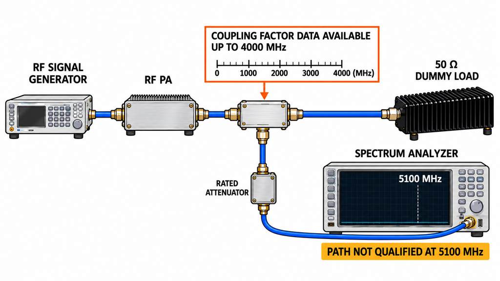
A spectrum analyzer’s upper frequency limit is only one requirement. Every component between the declared reference plane and the analyzer input must be suitable for the frequency and signal level being measured.
In a typical conducted PA test, the output path terminates in a suitably rated load, while a controlled sampling path feeds the analyzer through appropriate coupling and attenuation. A directional coupler can have different coupling factors at the fundamental and harmonic frequencies. Attenuators, cables, and adapters also introduce frequency-dependent losses. Those differences must be accounted for when correcting the analyzer reading to the PA output reference plane.
For each required harmonic frequency, check that:
- The analyzer and complete sampling path support the frequency.
- Coupling factors and path losses have valid frequency-specific supporting data.
- Analyzer input levels remain safe and within a sufficiently linear operating region.
- Sensitivity and usable dynamic range are adequate for the applicable limit.
- The reported result uses valid corrections to the declared reference plane.
Consider a hypothetical test requiring the third harmonic of a 1700 MHz fundamental, at 5100 MHz. If the analyzer supports 5100 MHz but the available coupling-factor evidence stops at 4000 MHz, the complete path remains unqualified at the required harmonic frequency.
No visible harmonic peak is not automatically a passing result. If the corrected measurement floor or detection capability cannot establish whether the harmonic satisfies the applicable limit, keep the result unresolved. Before using a non-detection as acceptance evidence, document the usable detection capability and apply the required uncertainty treatment and decision rule. Do not assume a universal measurement-floor margin.
Instrument-generated harmonics can also produce misleading readings. Strong fundamental energy reaching the analyzer may generate apparent higher-order components inside its receiver. A controlled change in analyzer input attenuation can help investigate this possibility, provided the PA operating state remains fixed.
Resolve instrument distortion, missing frequency corrections, or inadequate sensitivity, and confirm the required RF power amplifier test conditions before using the reading for acceptance.
5. Are the Signal, RBW, and Reference Plane Valid for the Claimed Result?
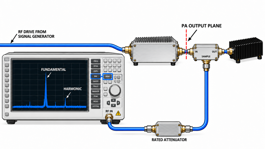
A report stating “−50 dBc at the second harmonic” leaves the result undefined unless it also identifies the fundamental frequency, waveform, PA operating condition, reference plane, and measurement method.
For a discrete CW harmonic, resolution bandwidth (RBW) affects the displayed noise floor and the ability to resolve a weak component. Under valid measurement conditions, changing RBW should not be interpreted as changing the power generated by the PA.
A modulated waveform may require a specified measurement bandwidth, detector or averaging method, and integration basis. A single marker value should not be treated as total harmonic-related power unless it meets the required measurement definition.
A dBm value represents absolute power at the stated reference plane. A dBc value expresses power relative to a defined carrier or fundamental reference. For a discrete CW harmonic, calculate the relative level from corrected harmonic and fundamental powers at the same reference plane and compatible operating state. Combining an analyzer-input reading with an uncorrected generator setting does not establish that comparison.
Check the actual RF operating condition as well. A nominal drive setting cannot replace a required input-power measurement, and a cold-state record cannot satisfy a requirement for hot-state evidence.
Before comparing rows, confirm compatible frequencies, harmonic orders, waveforms, power states, RBW or measurement bandwidth settings, detector methods, corrections, and reference planes. Mark a row Not Comparable Yet when a necessary condition remains unresolved.
6. Is the Result From the Source, Bare PA, or Filtered Assembly?
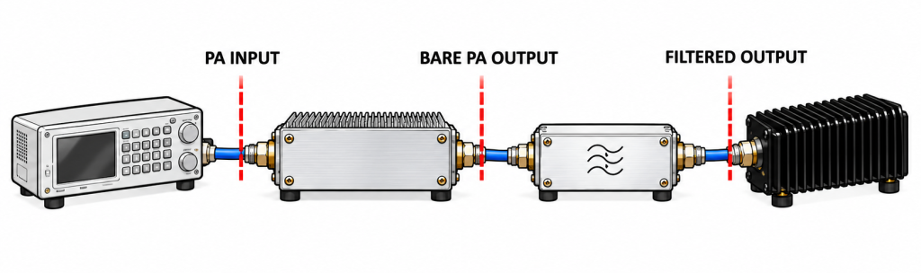
The signal source may contain unwanted spectral components before amplification. The PA can pass, amplify, or interact with those components while generating additional nonlinear products. An external output filter may then attenuate some of that energy.
Keep three measurement boundaries separate. A source-input measurement characterizes the signal presented to the PA under the defined drive condition. A bare-PA measurement describes the spectrum at the PA output plane before an external output filter. A filtered-assembly measurement describes the spectrum at the specified downstream plane with the documented filter and RF path installed.
A filtered-assembly result cannot establish the bare PA’s harmonic level, and a bare-PA result cannot establish the complete filtered assembly’s performance. If a bare-PA requirement is supported only by a filtered-assembly reading, the required evidence is still missing.
Determining the origin of unwanted RF amplifier output components requires source characterization before the measured harmonic content can be attributed to the PA. An output component already present at the PA input cannot be assigned entirely to the PA. Subtracting input and output readings in dB is not generally sufficient to isolate internally generated distortion.
When the evidence cannot separate contributions, report the observed output spectral content under the defined source and PA operating conditions. Do not describe it as distortion generated solely inside the amplifier.
7. How Should Missing Harmonic Evidence Be Handled Before Acceptance?

Use a harmonic test coverage and evidence matrix with one row for each required fundamental frequency, harmonic order, and operating condition. If the same frequency–harmonic pair requires different waveforms, PA output states, thermal conditions, or filter configurations, record those states separately. Matching frequencies do not make the records interchangeable.
Each row should identify the available measurement, any unresolved condition, and the action needed to close the gap. The two hypothetical rows below illustrate a missing correction and an unqualified measurement path.
| Fundamental f | Harmonic order | Frequency nf | Waveform / power state | Reference plane | Filter state | Full path qualified at nf? | Raw analyzer reading | Corrected result | Applicable limit source | Evidence status | Next action |
|---|---|---|---|---|---|---|---|---|---|---|---|
| fA MHz | 2 | 2fA MHz | Illustrative CW / defined PA output state | PA output connector | Bare PA, no external filter | Not yet; correction unresolved | Hypothetical capture exists; value omitted | Path correction unresolved | Project specification; reference pending | Not Comparable Yet | Supply valid 2fA correction and requirement reference; establish corrected result |
| fA MHz | 3 | 3fA MHz | Same illustrative state | PA output connector | Bare PA, no external filter | Not established at 3fA | No valid reading | Not available | Project specification; reference pending | Evidence Missing | Qualify path at 3fA, identify requirement, and perform test |
Swipe horizontally to review all twelve evidence fields →
For an actual acceptance record, enter the approved test points, documented operating conditions, measurement records, and specification references. Link each reported result to its raw evidence and correction data.
Where a result is specifically attributed to PA-generated harmonics, also identify the relevant source-baseline measurement under a compatible input condition. Reference-plane and filter-state records alone do not establish spectral origin.
When unit-level evidence is required, identify the model, configuration, and serial number. Keep batch-level or configuration-level evidence labeled according to its actual scope.
The following labels are working categories for this review, not universal contractual acceptance dispositions.
Evidence Missing: A required observation has not been established. Identify whether the gap is an unmeasured point, an unsupported frequency, or missing measurement-path qualification, then request the corresponding evidence.
Not Comparable Yet: A measurement exists, but a necessary condition, correction, reference plane, or measurement definition remains unresolved. Reconcile the records or request a valid retest.
Comparable: The measurement supports the intended comparison. Evaluate it against the applicable requirement; this label does not mean the result passes.
A report may be partially comparable. For example, second-harmonic results may be usable at the agreed frequencies while third-harmonic evidence remains incomplete. Restrict the comparison to the valid rows.
A valid measurement that exceeds its applicable limit requires evaluation under the project’s decision rule. It is a different issue from missing evidence. An undefined limit is a requirements gap and cannot support a pass decision.
Request the missing record or retest for the exact frequency, harmonic order, and operating state concerned. Another general spectrum screenshot may leave the same gap unresolved.
Shipment release requires broader C-UAS RF PA acceptance evidence, including unit identity, configuration, reliability, protection, and other agreed requirements.
Conclusion
Compare individual harmonic results only where the frequency, operating condition, measurement method, path, and reference plane support the comparison. Closing the full required test scope is a separate decision: every mandatory frequency–harmonic–operating-state combination needs usable evidence or an explicitly approved exception under the acceptance plan. An exception must remain identified as an exception, not as a measured pass.
Complete the matrix before signing off the harmonic evidence. Record which rows can be evaluated, which need supporting documents, and which require another measurement. Apply the approved limits and decision rules to the valid results; do not extend the conclusions to untested frequencies or operating states.
For a project review with RF SKYPOWER, send the required operating frequency range and test points, output power, waveform and drive condition, harmonic orders and limits, reference plane, filter configuration, thermal conditions, and report requirements. Include the matrix and its unresolved rows through the RF SKYPOWER engineering contact page.