










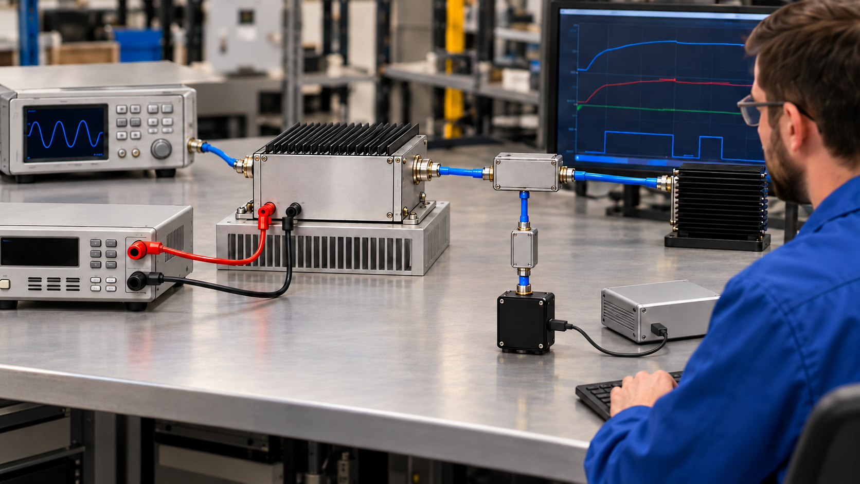
A full-power RF PA test has run long enough only when it meets the agreed duration requirement and shows that the required thermal state and RF performance were maintained under the specified operating conditions. No single RF PA test duration is sufficient for every full-power operating condition or acceptance objective.
A final power reading covers its measurement interval. Sustained output requires RF-power records covering the claimed period, even if the temperature looks stable. Start by identifying what the test was meant to demonstrate: a brief rated-power measurement, operation through warm-up, or uninterrupted full-power output after a defined thermal state was reached.
1. How Long Is Long Enough for a Full-Power RF PA Test?
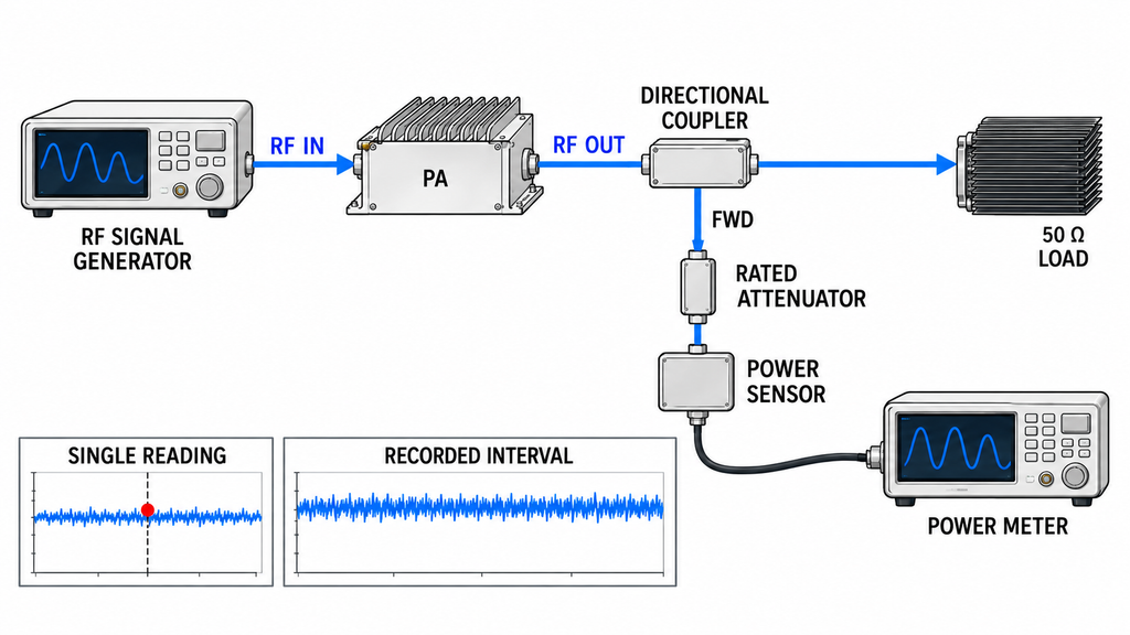
Choose the duration for the acceptance objective and operating conditions. A short measurement may establish output power at a specified frequency and operating point; hot-state performance needs evidence after the required thermal state has been reached. An RF power amplifier swept test may verify the prescribed dwell at each frequency, but it does not by itself prove a longer continuous hold at any one frequency.
For hot-state acceptance, define the thermal-stability criterion and the performance limits that must be met afterward. If the requirement includes an uninterrupted holding period, the run must satisfy both the stability criterion and the full hold duration. Assess a short-duration power test against its stated requirement, without adding an unagreed thermal-soak requirement.
Define full power in the test plan by specifying the signal mode (CW, pulsed, or modulated), the applicable power metric (such as average power, peak power, or peak envelope power), the RF output reference plane, and the acceptable output range. The plan should also state whether the duration applies from the first valid RF output, from confirmed thermal stabilization, or to another agreed interval.
Before evaluating a supplier’s runtime, obtain the approved objective and duration rule, along with the frequency-point plan and Pin/Pout measurement boundaries used in the swept-frequency full-power RF PA test.
2. Which Operating Conditions Must Remain Valid During the Run?
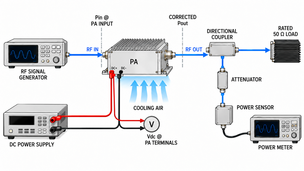
Only time spent under the approved operating conditions can support the corresponding full-power claim. Those conditions include the test frequency or programmed sequence, waveform, power definition, duty cycle, actual RF input power (Pin) at the PA input reference plane, and corrected output power (Pout) at the specified output plane. They also include the rated load and reflection conditions, DC voltage measured at the module terminals under load, cooling arrangement, ambient conditions, and relevant protection settings.
For a nominal 28 V module, verify voltage at the PA terminals under load. Establish actual Pin at the PA input plane and corrected Pout at the agreed output plane from the measurement and correction records. Generator settings and downstream instrument readings alone do not establish those values.
Mark changes in drive, supply, cooling, load, and protection state, then check the affected interval against the approved limits. An approved closed-loop Pin adjustment can remain part of the same test if actual drive stays within its specified limits and the applicable Pout, gain, and operating-state criteria are met. Handle supply excursions, unapproved setup changes, or disqualifying protection events under the interruption rules before counting the affected time.
3. What Evidence Marks the Start of a Stable Thermal State?
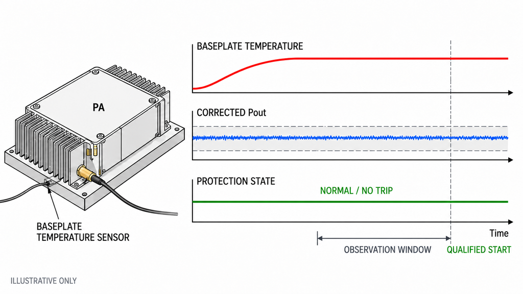
Before testing, define the temperature sensor and its location, such as the case, baseplate, or heatsink; the permitted change; the observation window; and how that window establishes the qualifying time. These locations are not interchangeable, and a stable case or heatsink reading is not a direct junction-temperature measurement.
Check Pout, actual Pin, module-terminal voltage and current, relevant reflected-power or VSWR readings, and protection status over the same observation window. A temperature plateau cannot qualify the run if Pout falls below the approved minimum or its drift exceeds the specified limit. Apply the protection-state criteria as well, even if output appears stable during foldback. Use the pre-agreed confirmation rule and continuous records to assign the timestamp. Backdate it to an earlier threshold crossing only if the protocol permits this and the full observation window supports that choice.
Record the sensor, stabilization criterion, observation interval, and qualifying timestamp. If any is missing, request the information needed to establish the start. No model-independent 80-, 100-, or 120-minute threshold applies, and a valid hot-state Pout measurement does not, by itself, prove the duration of the subsequent full-power hold.
4. How Should Warm-Up, Stable-State Hold, and Interruptions Be Counted?
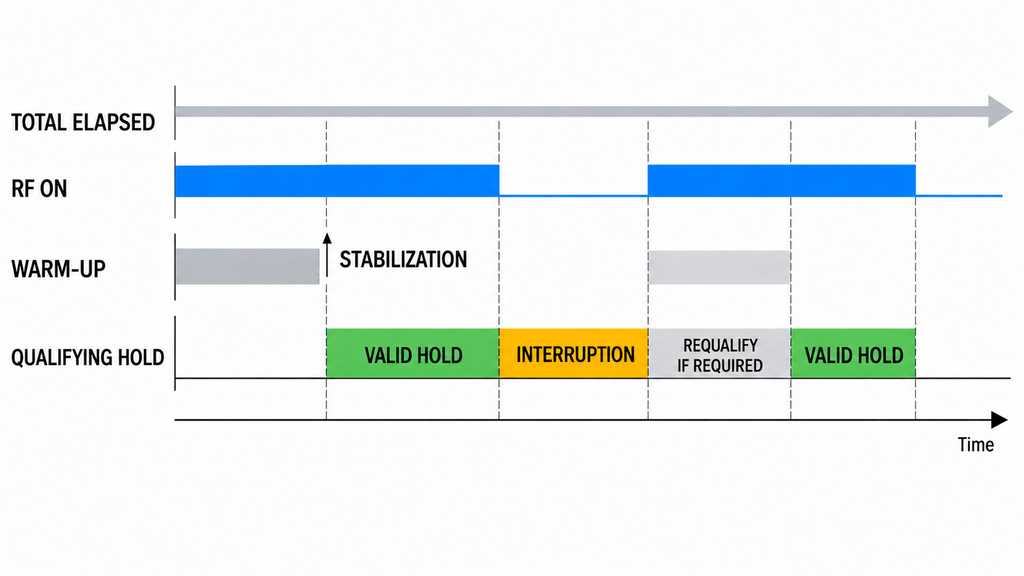
Record when the unit was powered, when valid full-power RF output began, the warm-up interval, the stabilization timestamp, the qualifying hold, and the test end. Some periods overlap. The instrument’s total elapsed-time counter does not identify how long the PA met the acceptance conditions.
When Does the Valid Hold Window Begin?
For a requirement to hold full power after thermal stabilization, use the start permitted by the approved stabilization and timing rules. The thermal and RF records must support that start; a single temperature reading inside a limit does not satisfy an observation-window requirement.
Warm-up may count toward a requirement defined as total valid RF-on time, if the test plan says so. It does not automatically count toward an additional post-stabilization hold. The reviewer should record both intervals separately and compare the applicable one with the contracted requirement.
For each operating condition with a continuous post-stabilization requirement, find the longest uninterrupted qualifying interval after its documented stabilization or required requalification point. Check that it stayed within the approved RF, electrical, thermal, and protection limits throughout, then compare that interval with the required hold. For a continuous RF-on requirement without a thermal gate, use the approved valid RF-on start. Add separate intervals only if the pre-approved procedure permits cumulative time and defines how interruptions affect thermal qualification.
What Happens After an Interruption or Configuration Change?
An RF shutdown, protection trip, output reduction, supply interruption, change in drive, cooling adjustment, or change in waveform or frequency may break the qualifying interval. Whether the run must restart, re-establish thermal stability, or can resume depends on rules agreed before testing and on what the event records show.
Locate each interruption in the event log and determine whether the previous thermal qualification remains valid. If recovery or re-stabilization is required, a new qualifying interval begins only after that requirement is met. Missing event coverage leaves continuity unproven.
5. Which Time-Series Records Prove the Duration Was Valid?
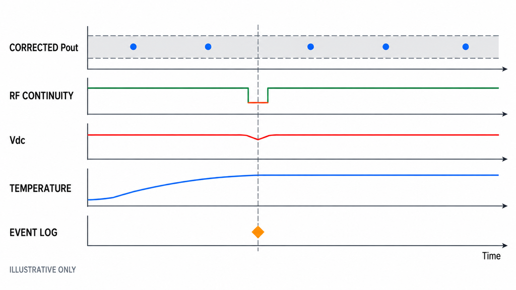
Align the timestamps from the power measurements, DC supply, temperature channels, RF source or controller, and protection/event log. Record sampling intervals and gaps so another engineer can reconstruct the qualifying period.
Slow temperature sampling may track thermal drift but miss a brief protection trip or RF dropout. The RF-power acquisition must capture interruptions that would invalidate the continuous hold, or be supplemented by an RF-output monitor validated to detect them with synchronized event timestamps. An RF-enable command or controller status alone cannot prove output continuity. Keep the Pout record needed to verify the power limits alongside any event log; a slowly sampled average-Pout trace can miss dropouts between readings.
Retain the raw power-meter readings, applicable correction factors, and corrected Pout at the specified PA output reference plane. Keep actual Pin traceable to the PA input reference plane throughout the claimed interval. Time-align these values with frequency, waveform, duty cycle, module-terminal Vdc and Idc, temperature-sensor identity, and the required forward/reflected-power or VSWR measurements. Timestamp changes to the RF measurement path or correction basis, manual adjustments, alarms, foldback, shutdowns, and restarts. Account for the measurement method and uncertainty when judging a reading near an acceptance limit.
The table below is a requirements-and-evidence template for reviewing duration. It contains no measured RF SKYPOWER results and does not impose a universal per-unit test requirement.
| Review item | Must be defined before the test | Evidence required from the run | Decision supported |
|---|---|---|---|
| Test objective | Power metric, tested mode, duration requirement, and whether the result applies to a sample, batch, or identified unit | Approved procedure and its revision | Establish which time-based claim is being assessed |
| Qualified start | RF-on condition, frequency or sequence, Pin/Pout planes, load, supply, cooling, and allowed tolerances | Timestamped setup state and measurements at the eligible start | Determine when valid full-power operation began |
| Thermal state | Sensor location, stabilization criterion, and observation window | Time-aligned temperature and RF/electrical trends, with protection status | Establish whether and when the required thermal state was reached |
| Post-stabilization hold | Hold duration, start convention, and continuous-versus-cumulative rule | Start and end timestamps plus complete qualifying-interval records | Calculate the permitted hold time without counting warm-up incorrectly |
| Performance maintained | Pout/Pin definitions and limits; required DC, reflection, and protection boundaries | Raw power readings, applicable corrections, corrected Pout, actual Pin, Vdc/Idc, relevant FWD/REV or VSWR, and status trends | Check that the claimed interval remained within specification |
| Interruptions and adjustments | Events that invalidate time, allowed recovery, and restart rules | Timestamped alarms, trips, RF mutes, configuration changes, gaps, and restarts | Exclude or adjudicate affected intervals under the approved rule |
| Unit traceability | Model, hardware/control revision, serial-number scope, and test date | Identified report and data files tied to the tested sample or S/N | Prevent a representative run being mistaken for every delivered unit |
| Final disposition | Acceptance limits, evidence-completeness rule, and authority to decide | Qualified-duration calculation, exceptions, missing records, and documented disposition under the agreed reporting format | Accept the defined claim, hold for evidence, or require disposition/retest |
Identify unsynchronized timestamps, missing channels, and gaps in event coverage before accepting the claimed window. These gaps leave the duration unproven; they do not establish hardware failure.
6. How Does Frequency or Duty Cycle Change the Duration Review?
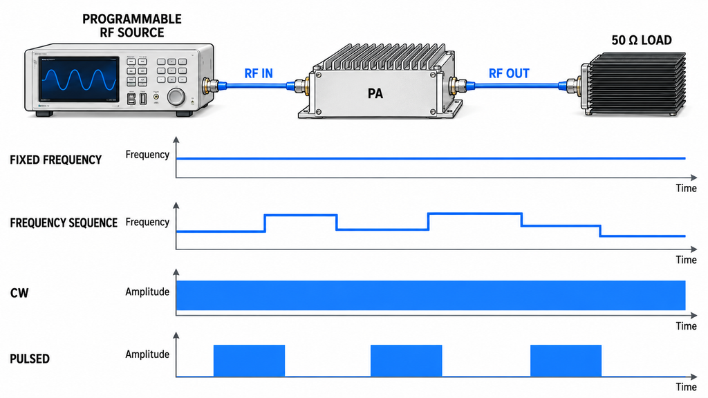
A valid hold at one frequency and waveform proves that hold only under the recorded conditions. Frequency-dependent efficiency, drive requirements, matching, and thermal dissipation may alter the operating burden. A different duty cycle or modulation profile can also change average dissipation even when a displayed peak-power figure appears similar.
The approved plan should identify the required frequency dwell points, any representative operating sequence, and the valid duration attached to each. A long single-frequency dwell and a repeated frequency-switching sequence answer different questions unless their equivalence has been established. Neither the center nor the band edge should be assumed to be the thermally worst condition without supporting assessment.
Record which frequencies, waveforms, duty cycles, cooling conditions, and time intervals the evidence covers, and which requested conditions remain untested. If deployment falls outside the tested conditions, request a justified representative test or an additional run.
7. When Should the Buyer Accept, Hold, or Repeat the Test?
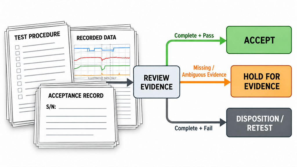
Accept the duration evidence when the required operating conditions, thermal criterion where applicable, holding rule, performance limits, and record coverage are satisfied. Name the tested configuration, qualifying interval, and sample or serial-number scope in the acceptance record. The result covers this duration requirement under those conditions, not untested frequencies, waveforms, antenna-chain performance, service life, or other acceptance items.
Hold the decision when the objective, start point, sensor criterion, timestamps, corrections, event history, or report identity is missing or ambiguous. Request the specific records needed to close the gap. Keep the hardware verdict open until the evidence supports it.
Apply the agreed nonconformance or retest process when complete records show a shorter qualifying hold than required, an out-of-limit RF condition, a disqualifying protection event, or a broken continuous period. Do not change the stabilization threshold or interruption rule after reviewing an unfavorable trace. If an essential rule was never agreed, resolve it before treating a repeated run as a valid acceptance test.
Use test video as supporting evidence of visible operation. It cannot replace synchronized RF, thermal, electrical, and protection records throughout the qualifying interval. Compare suppliers’ duration claims only when their power definitions, operating conditions, stabilization rules, continuity requirements, and evidence coverage are aligned or shown to be equivalent.
Specify whether the purchase requirement calls for design validation, lot sampling, or a test on every delivered unit. An S/N-linked report supports only the tests and data it contains. Likewise, a 72-hour RF PA batch burn-in record documents that screening process; it proves 72 hours of uninterrupted rated RF output only if the recorded conditions and time-series evidence establish that claim.
For any candidate in the RF Power Amplifier Modules range, model suitability and duration-test acceptance still require evidence under the proposed operating conditions.
Wideband RF PA Modules
Select a frequency band to compare standard 30 W–200 W models and open the applicable English PDF datasheets.
30–512 MHz · 5 standard models
| Power | Model / PDF | Psat min. / typ. | Current typ. / max. | Dimensions | RF input / output | Control |
|---|---|---|---|---|---|---|
| 30 W | 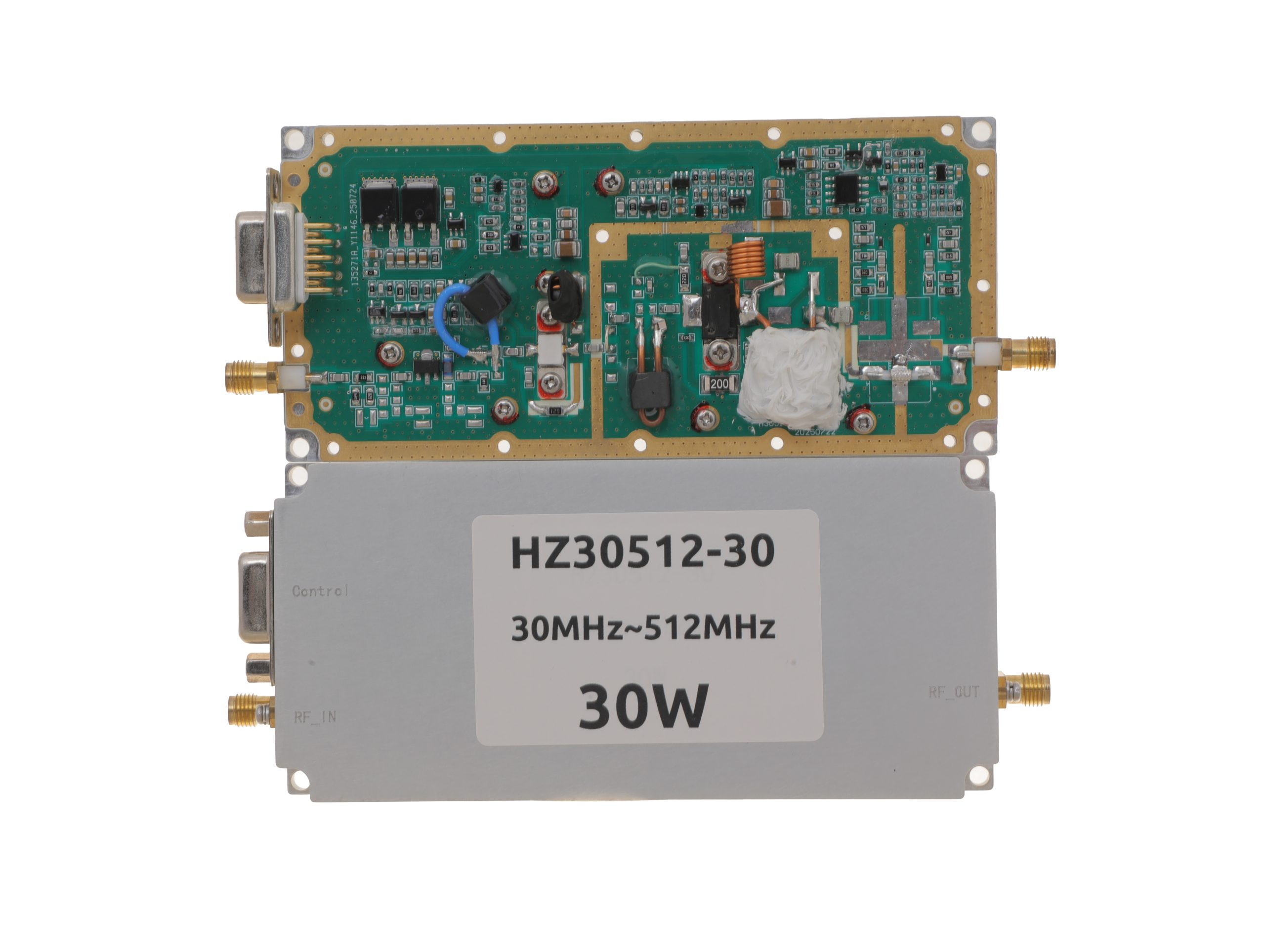 HZ30512-30NA1Open English PDF ↗ | 25 / 30 W | 3.2 / 4 A | 125 × 59 × 21.5 mmWeight: 0.5 kg | SMA-KFD46 / SMA-KFD46 | 9-pin D-Sub |
| 50 W | 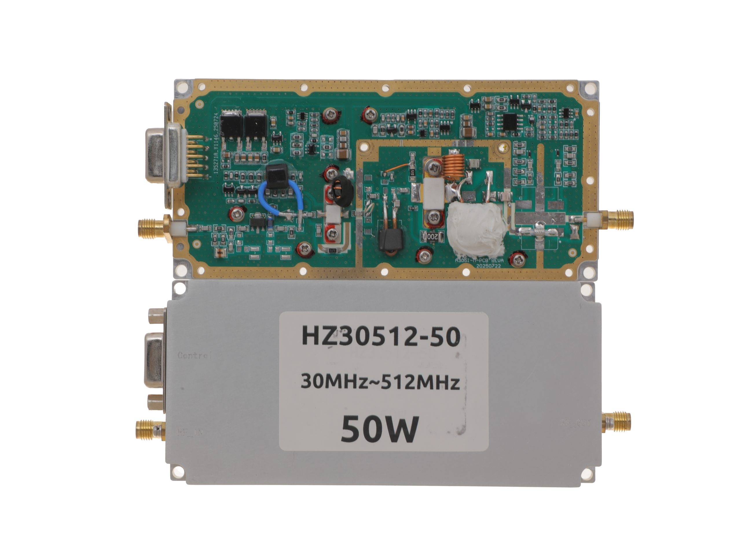 HZ30512-50NA1Open English PDF ↗ | 40 / 50 W | 7.2 / 9 A | 125 × 59 × 21.5 mmWeight: 0.5 kg | SMA-KFD46 / SMA-KFD46 | 9-pin D-Sub |
| 100 W | 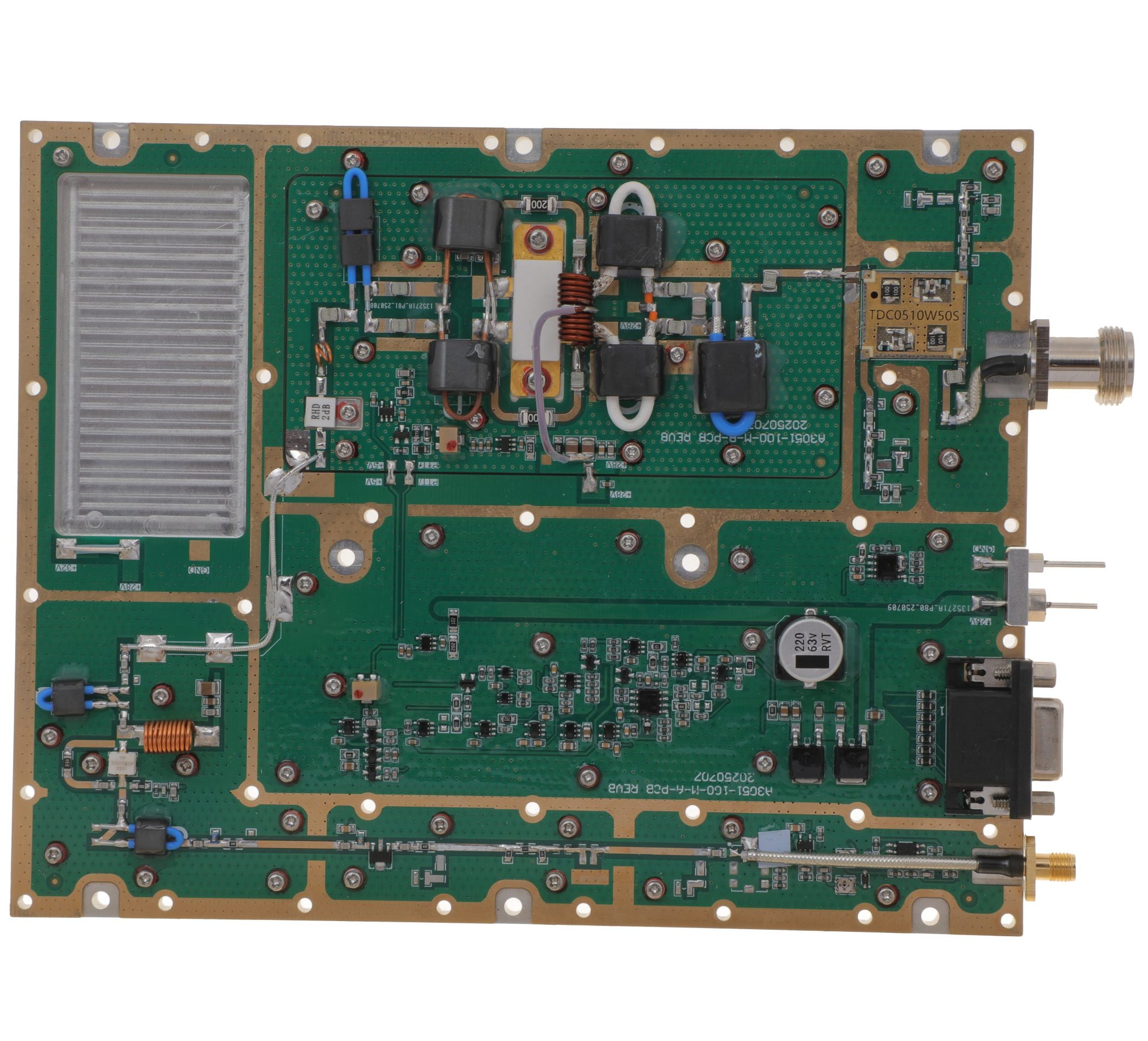 HZ30512-100NA1Open English PDF ↗ | 80 / 100 W | 14.5 / 18 A | 160 × 120 × 25 mmWeight: 1.4 kg | SMA-F / N-F | 15-pin D-Sub |
| 150 W | 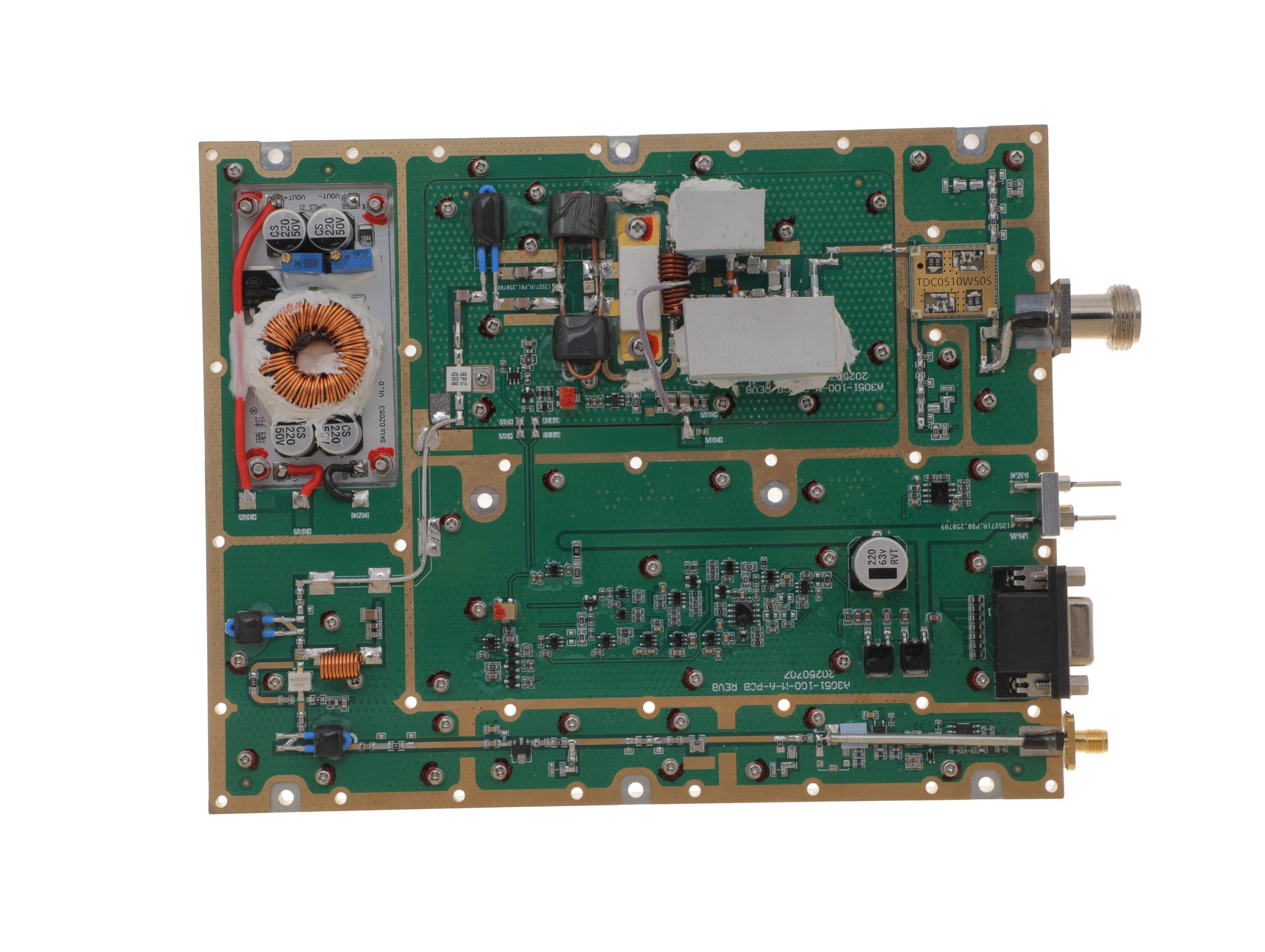 HZ30512-150NA1Open English PDF ↗ | 120 / 150 W | 16 / 20 A | 200 × 158 × 25 mmWeight: 1.4 kg | SMA-F / N-F | 15-pin D-Sub |
| 200 W | 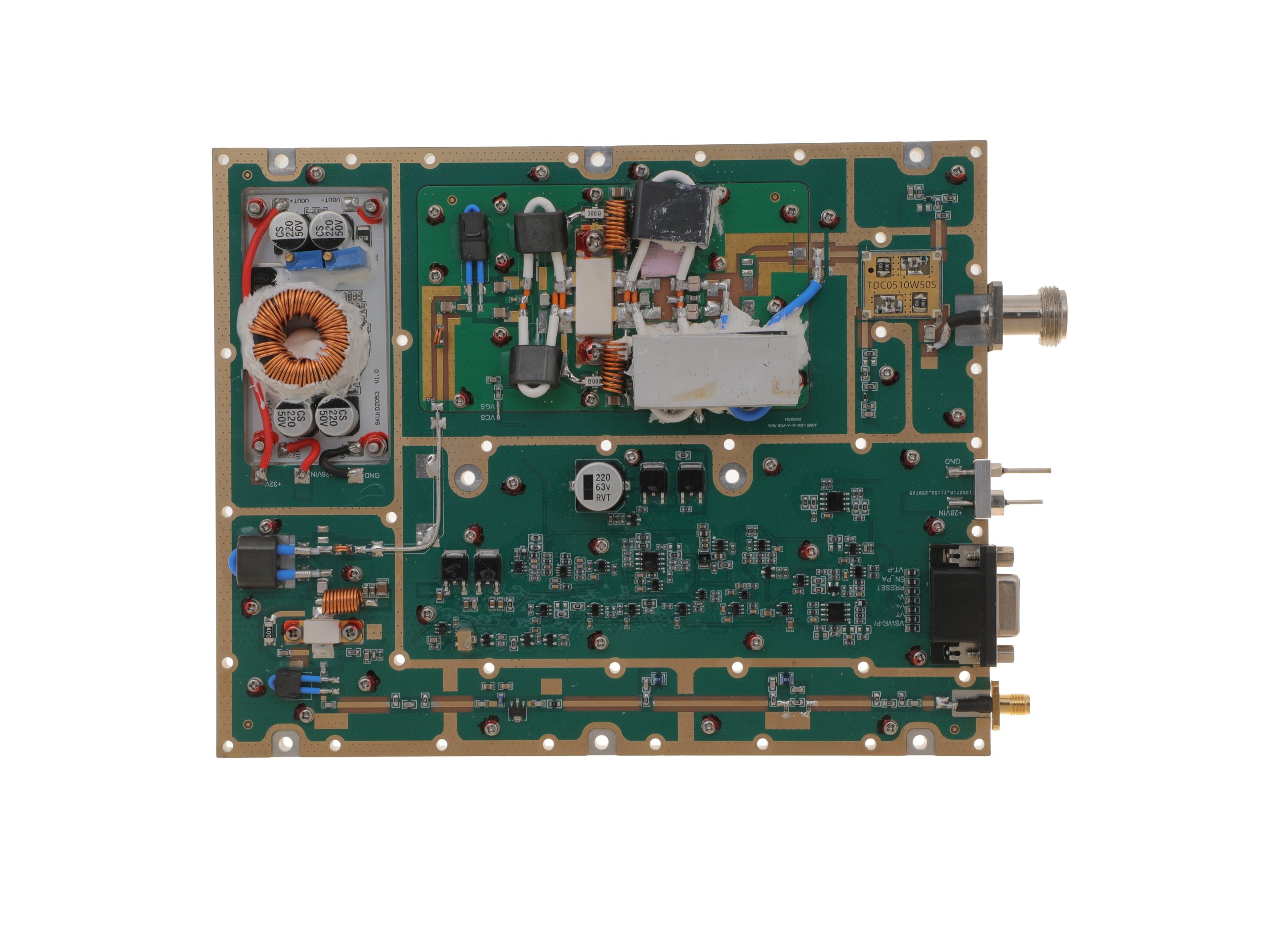 HZ30512-200NA1Open English PDF ↗ | 160 / 200 W | 29 / 36 A | 200 × 158 × 25 mmWeight: 1.4 kg | SMA-F / N-F | 15-pin D-Sub |
300–1200 MHz · 5 standard models
| Power | Model / PDF | Psat min. / typ. | Current typ. / max. | Dimensions | RF input / output | Control |
|---|---|---|---|---|---|---|
| 30 W | 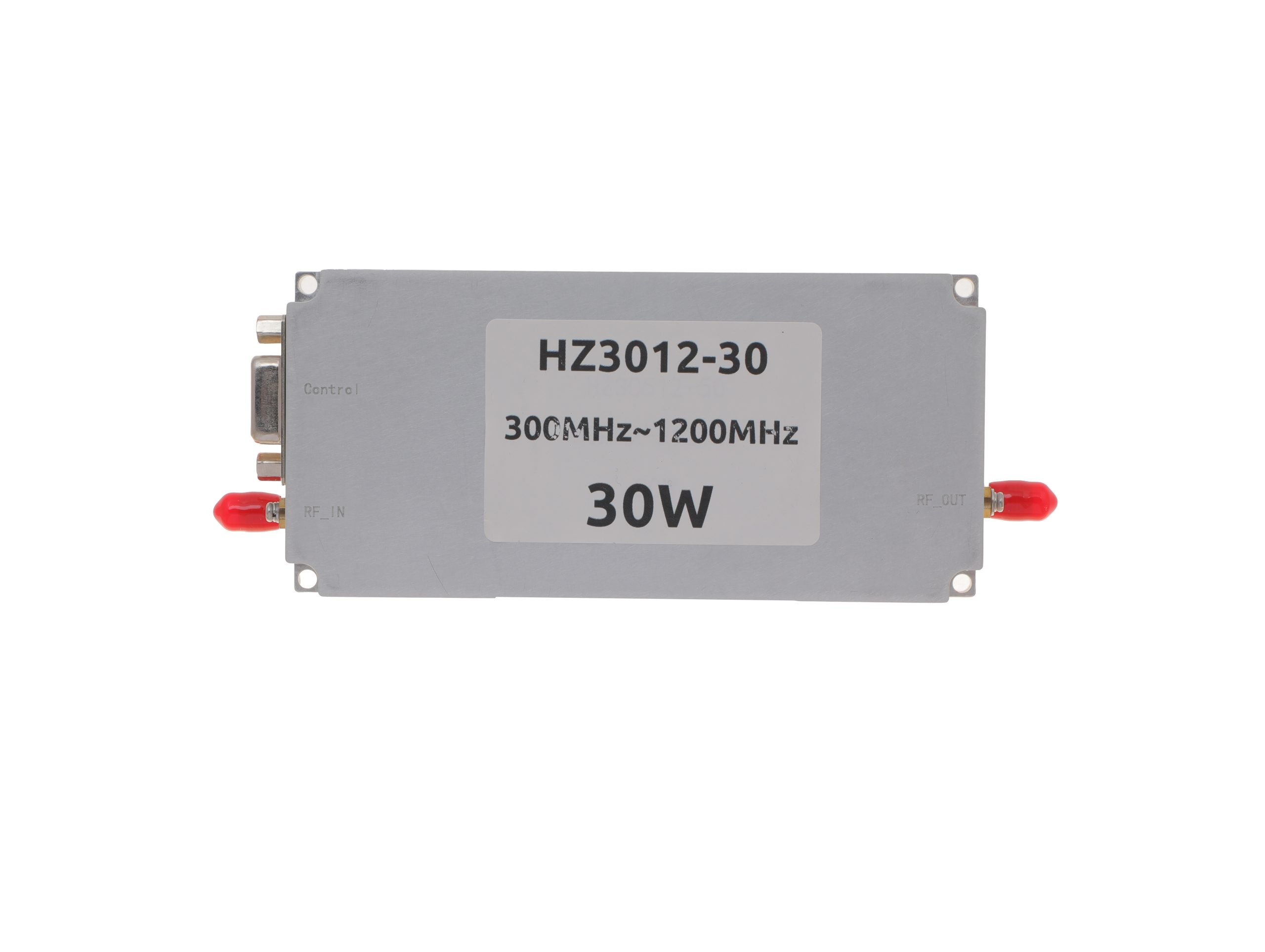 HZ3001200-30Open English PDF ↗ | 25 / 30 W | 2.4 / 3 A | 125 × 59 × 21.5 mm | SMA-KFD46 / SMA-KFD46 | 9-pin D-Sub |
| 50 W | 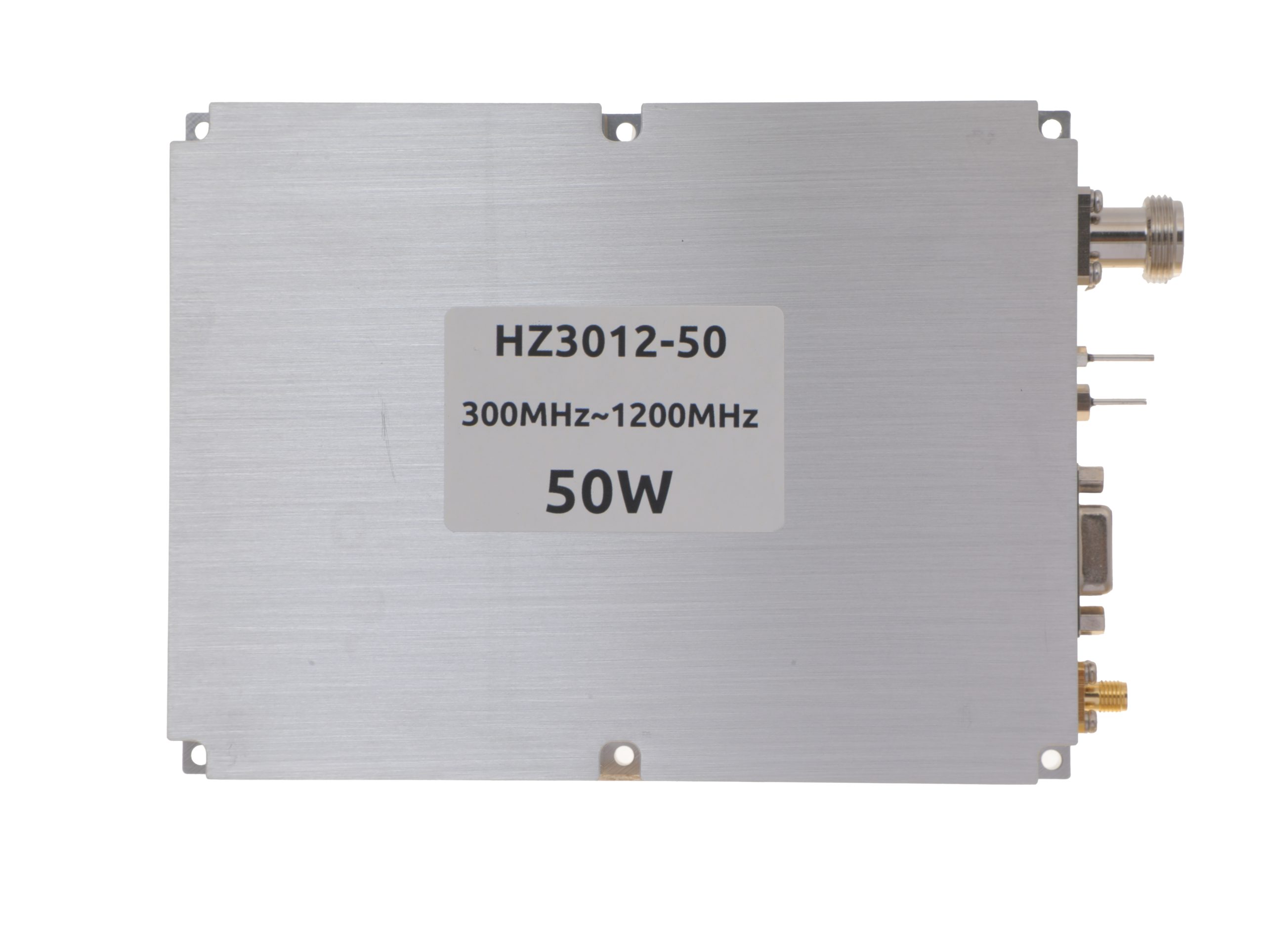 HZ3001200-50Open English PDF ↗ | 40 / 50 W | 5.6 / 7 A | 125 × 59 × 21.5 mm | SMA-KFD46 / SMA-KFD46 | 9-pin D-Sub |
| 100 W | 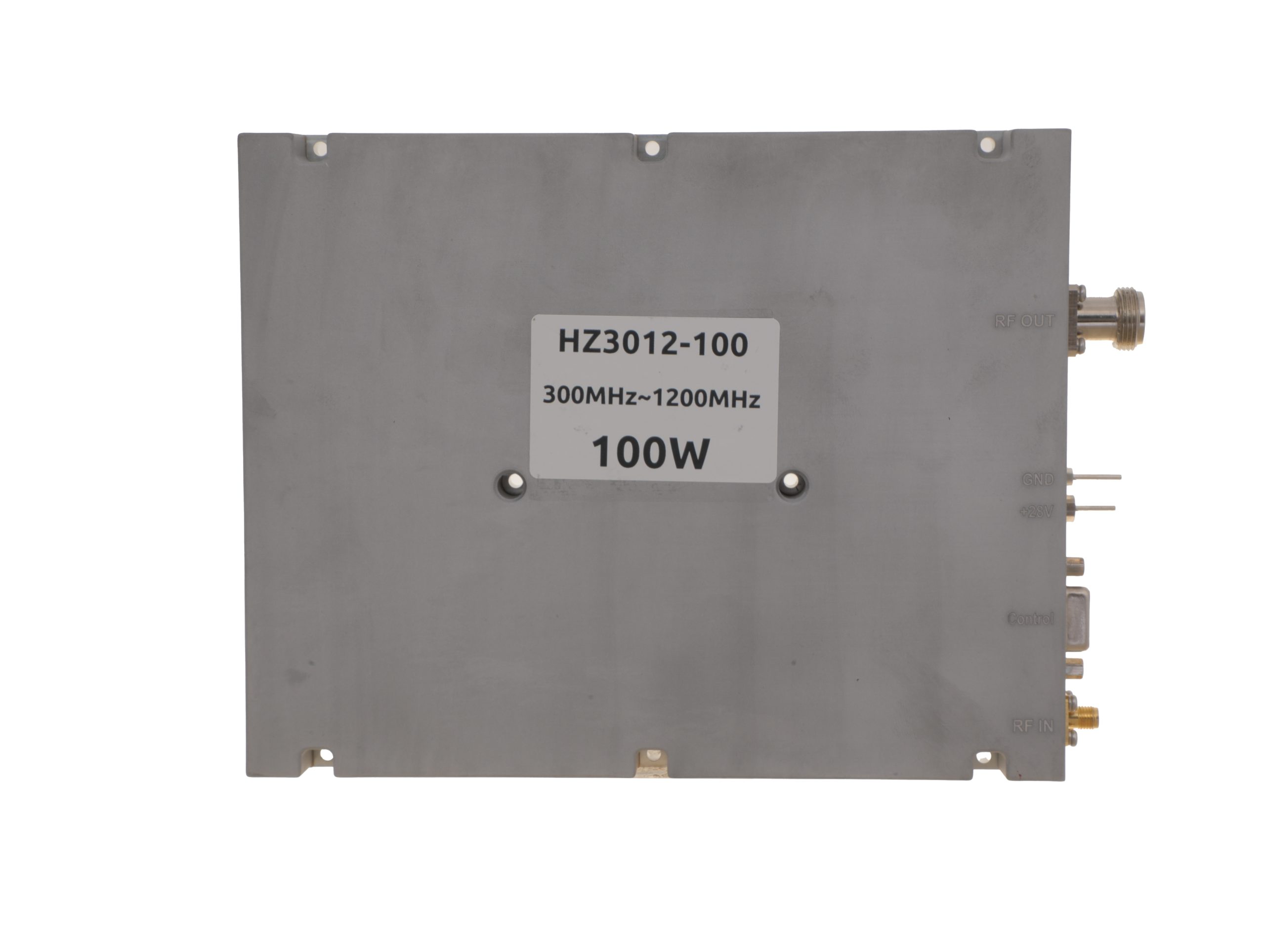 HZ3001200-100Open English PDF ↗ | 80 / 100 W | 11.5 / 14 A | 200 × 158 × 25 mm | SMA-F / N-F | 15-pin D-Sub |
| 150 W | 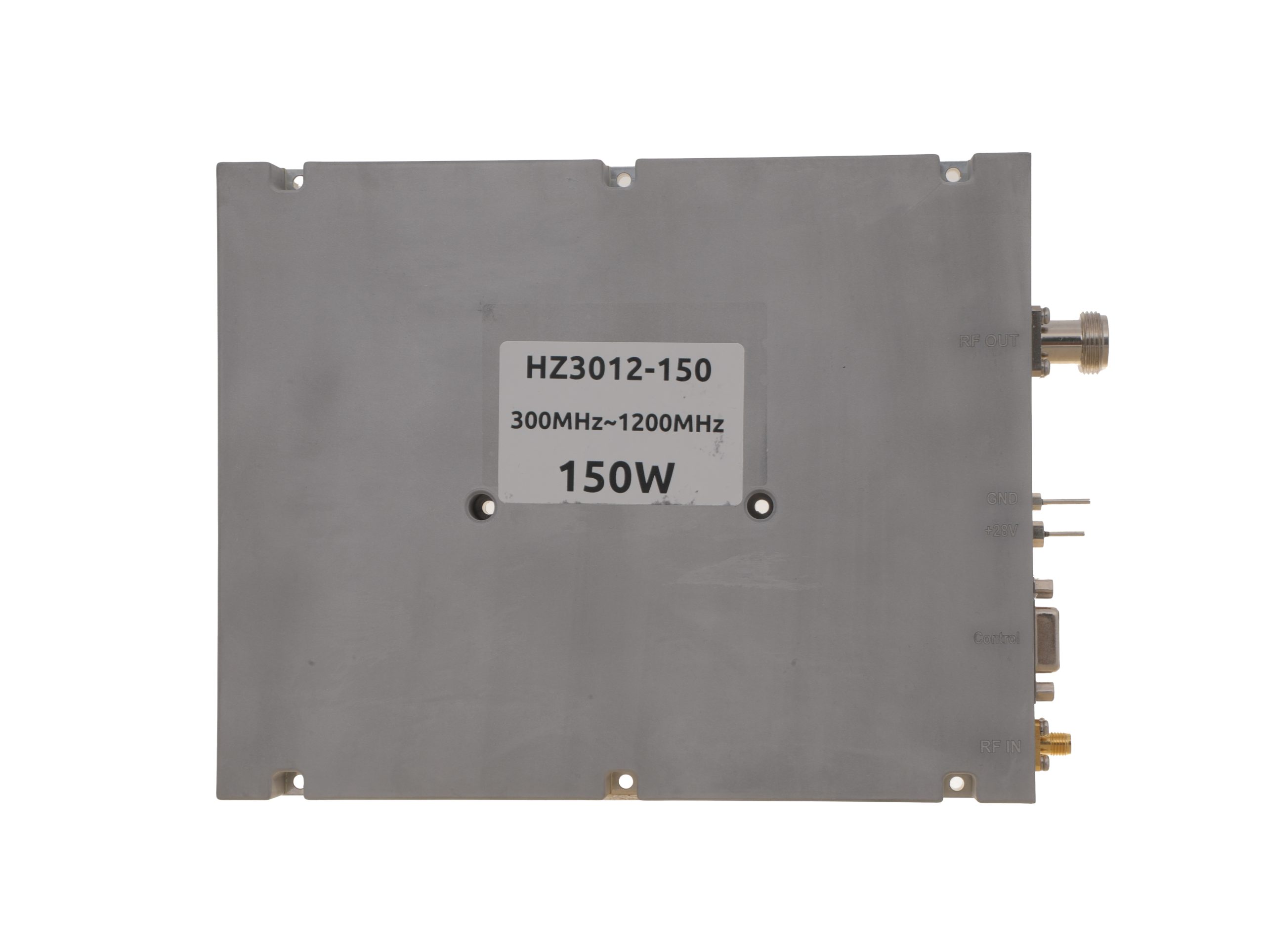 HZ3001200-150Open English PDF ↗ | 120 / 150 W | 18 / 22 A | 200 × 158 × 25 mm | SMA-F / N-F | 15-pin D-Sub |
| 200 W | 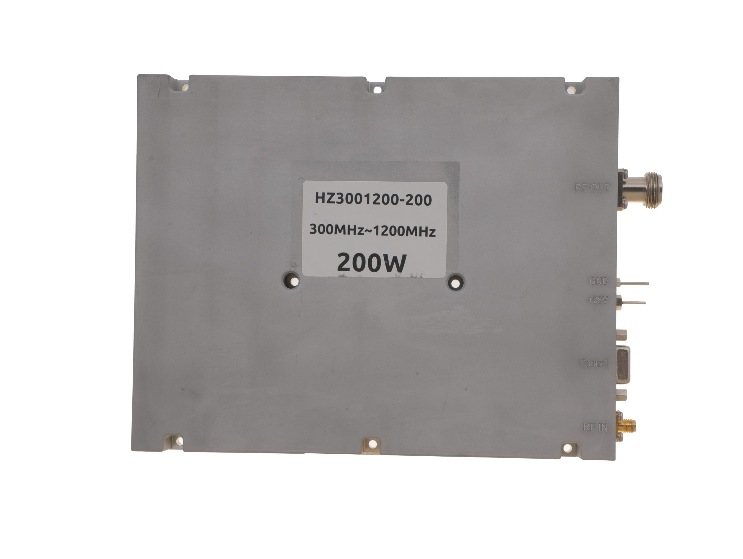 HZ3001200-200Open English PDF ↗ | 160 / 200 W | 24 / 29 A | 200 × 158 × 25 mm | SMA-F / N-F | 15-pin D-Sub |
300–1700 MHz · 5 standard models
| Power | Model / PDF | Psat min. / typ. | Current typ. / max. | Dimensions | RF input / output | Control |
|---|---|---|---|---|---|---|
| 30 W | 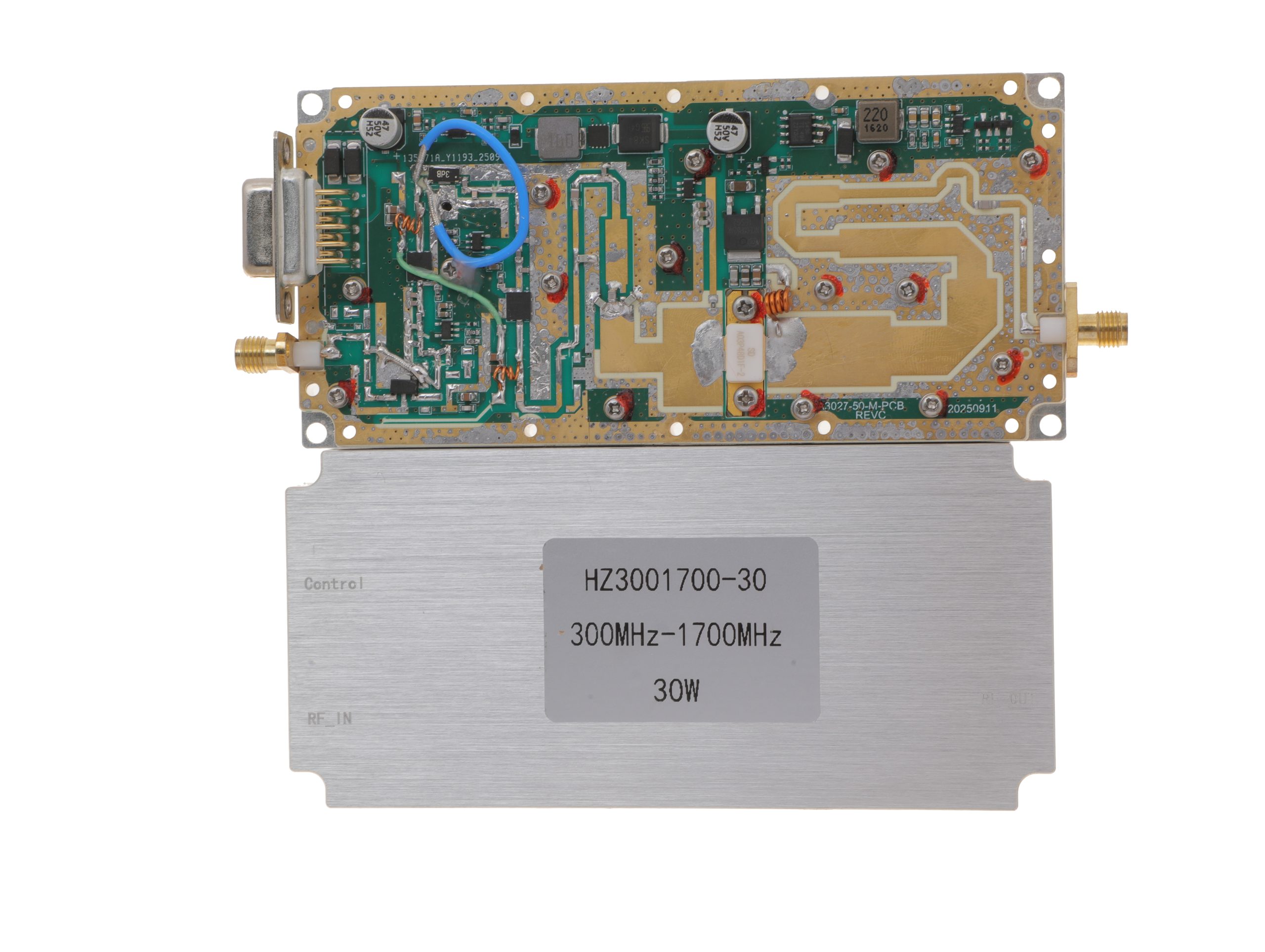 HZ3001700-30Open English PDF ↗ | 25 / 30 W | 2.4 / 3 A | 125 × 59 × 21.5 mm | SMA-KFD46 / SMA-KFD46 | 9-pin D-Sub |
| 50 W | 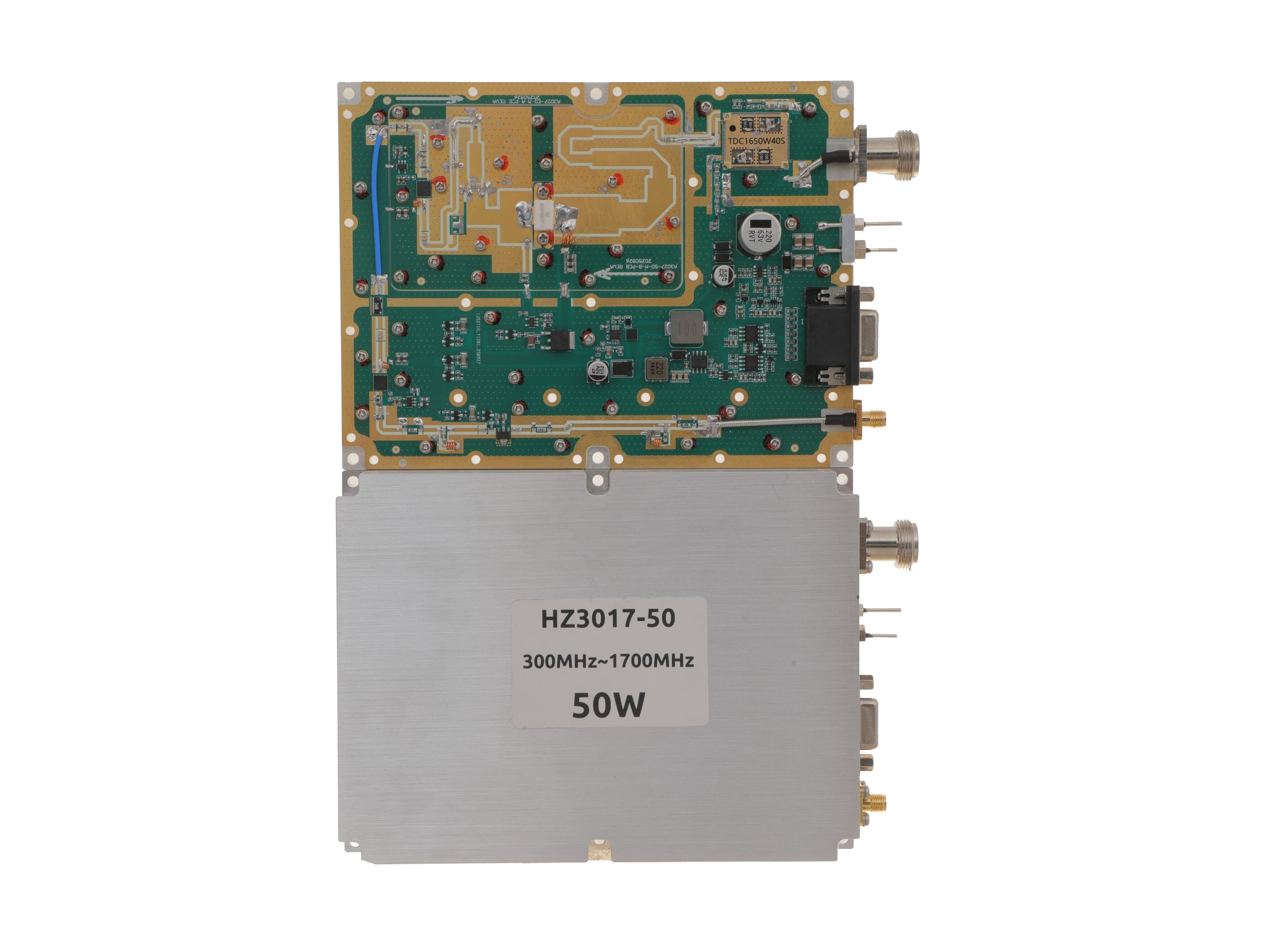 HZ3001700-50Open English PDF ↗ | 40 / 50 W | 5.6 / 7 A | 160 × 120 × 25 mm | SMA-F / N-F | 15-pin D-Sub |
| 100 W | 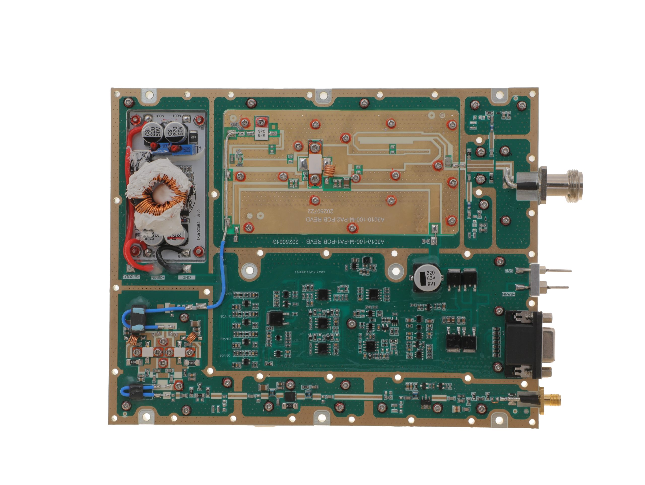 HZ3001700-100Open English PDF ↗ | 80 / 100 W | 11.5 / 14 A | 200 × 158 × 25 mm | SMA-F / N-F | 15-pin D-Sub |
| 150 W | 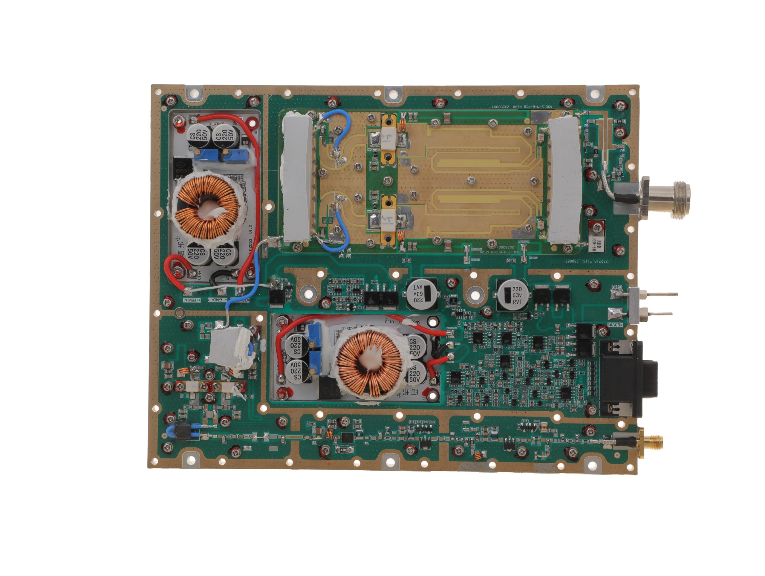 HZ3001700-150Open English PDF ↗ | 120 / 150 W | 18 / 22 A | 200 × 158 × 25 mm | SMA-F / N-F | 15-pin D-Sub |
| 200 W | 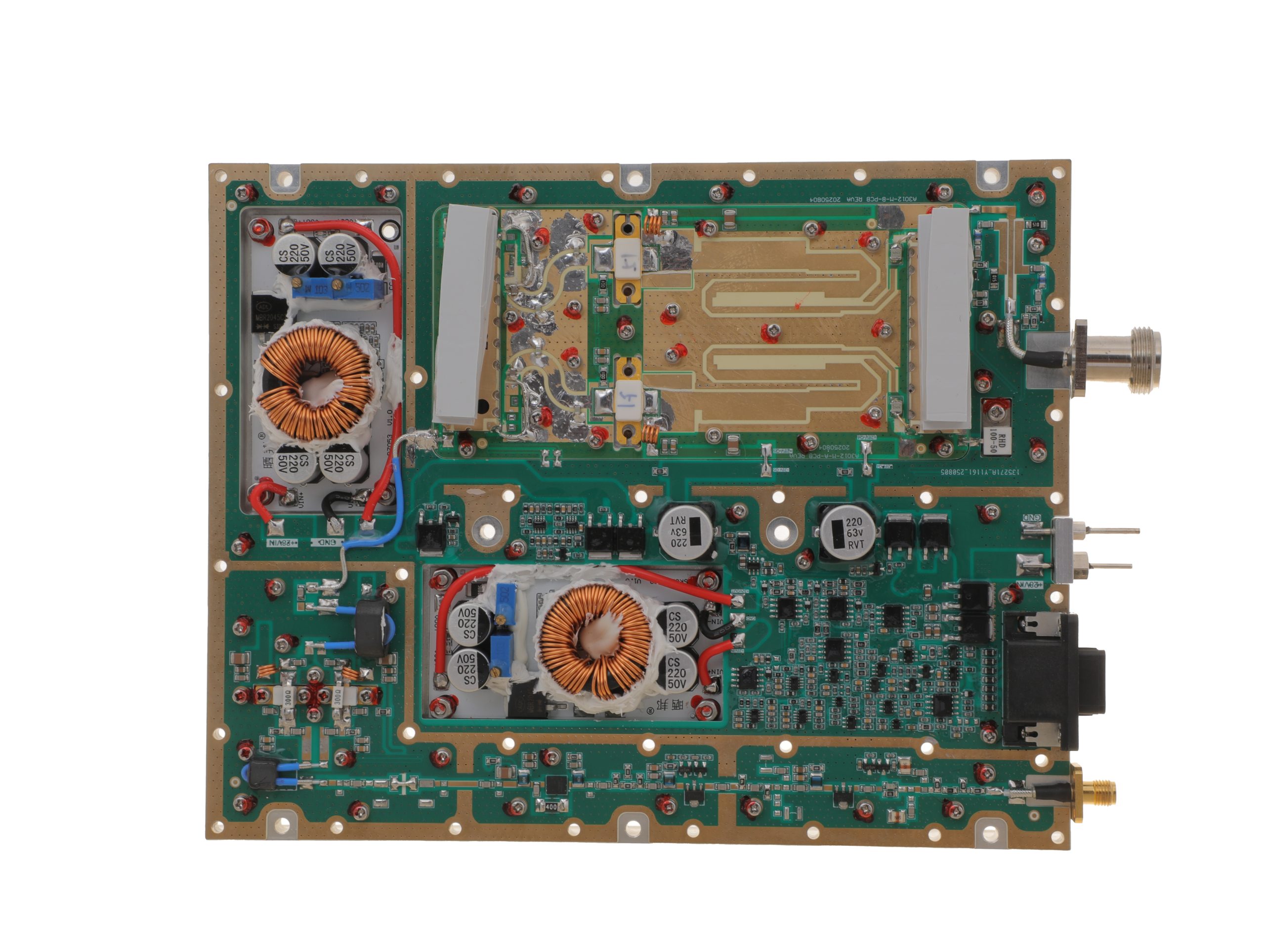 HZ3001700-200Open English PDF ↗ | 158 / 200 W | 24 / 29 A | 200 × 158 × 25 mm | SMA-F / N-F | 15-pin D-Sub |
300–2700 MHz · 5 standard models
| Power | Model / PDF | Psat min. / typ. | Current typ. / max. | Dimensions | RF input / output | Control |
|---|---|---|---|---|---|---|
| 30 W | 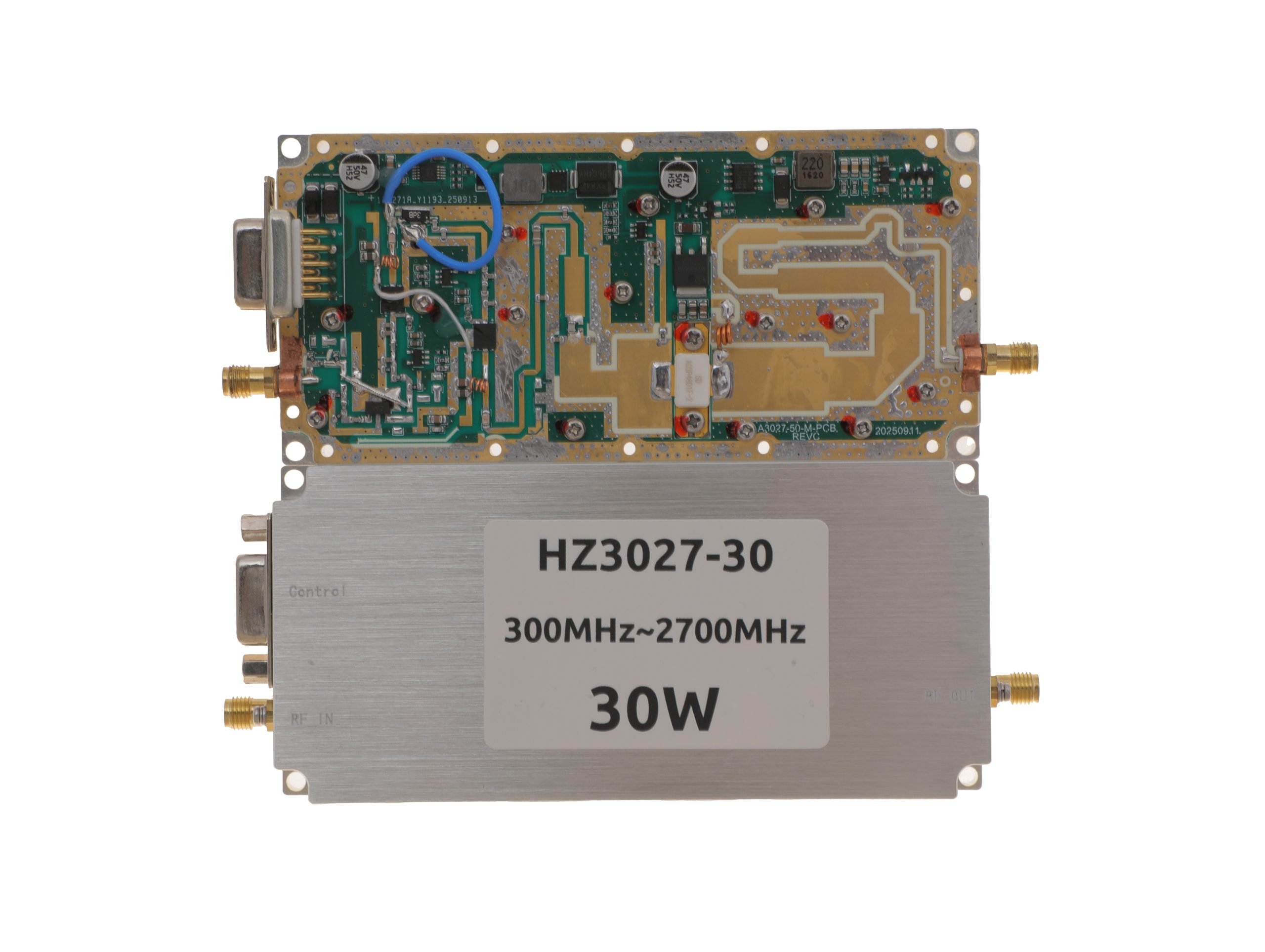 HZ3002700-30NA1Open English PDF ↗ | 25 / 30 W | 3.2 / 4 A | 125 × 59 × 21.5 mm | SMA-KFD46 / SMA-KFD46 | 9-pin D-Sub |
| 50 W | 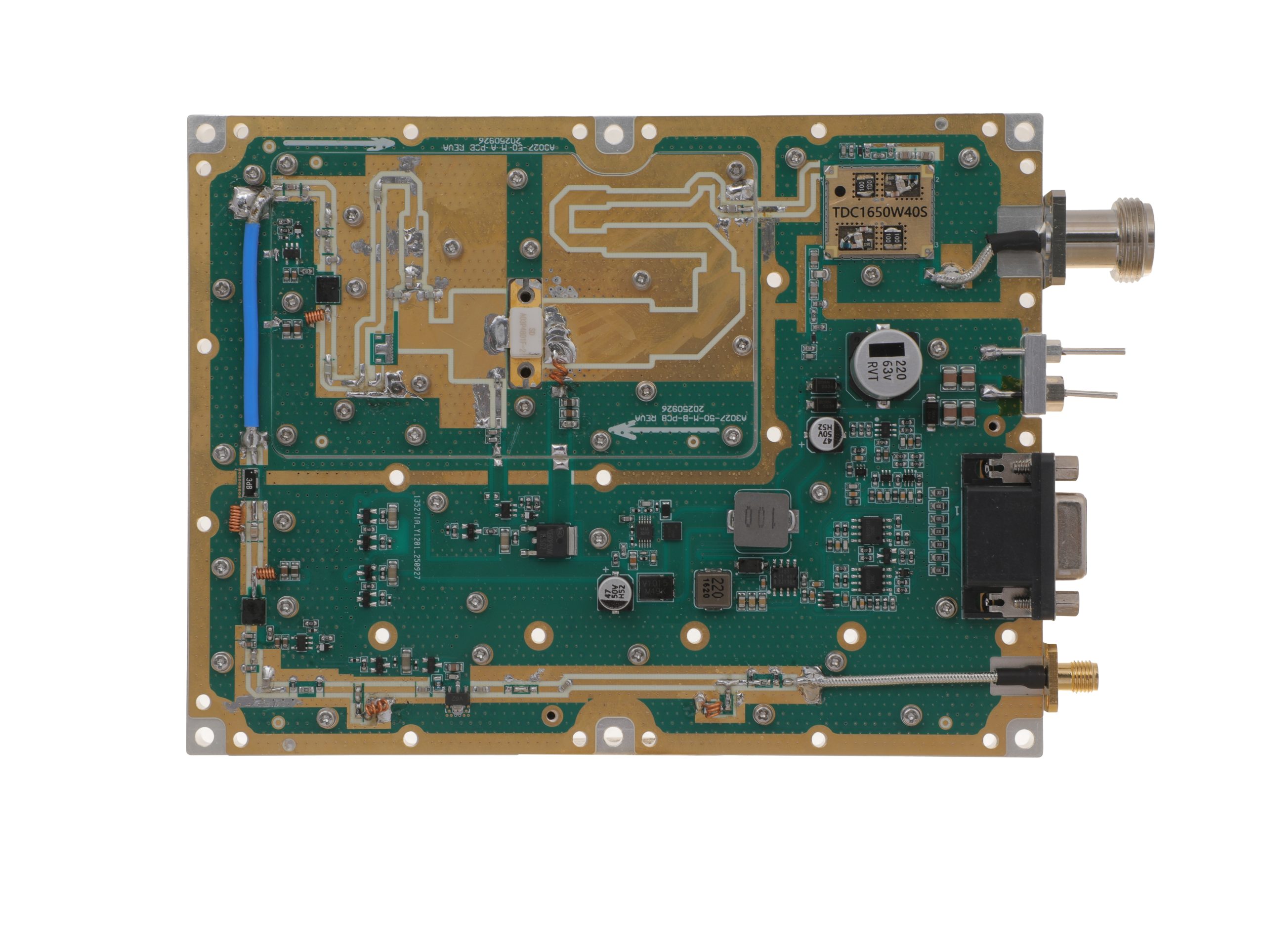 HZ3002700-50NA1Open English PDF ↗ | 40 / 50 W | 7.2 / 9 A | 160 × 120 × 25 mm | SMA-F / N-F | 15-pin D-Sub |
| 100 W | 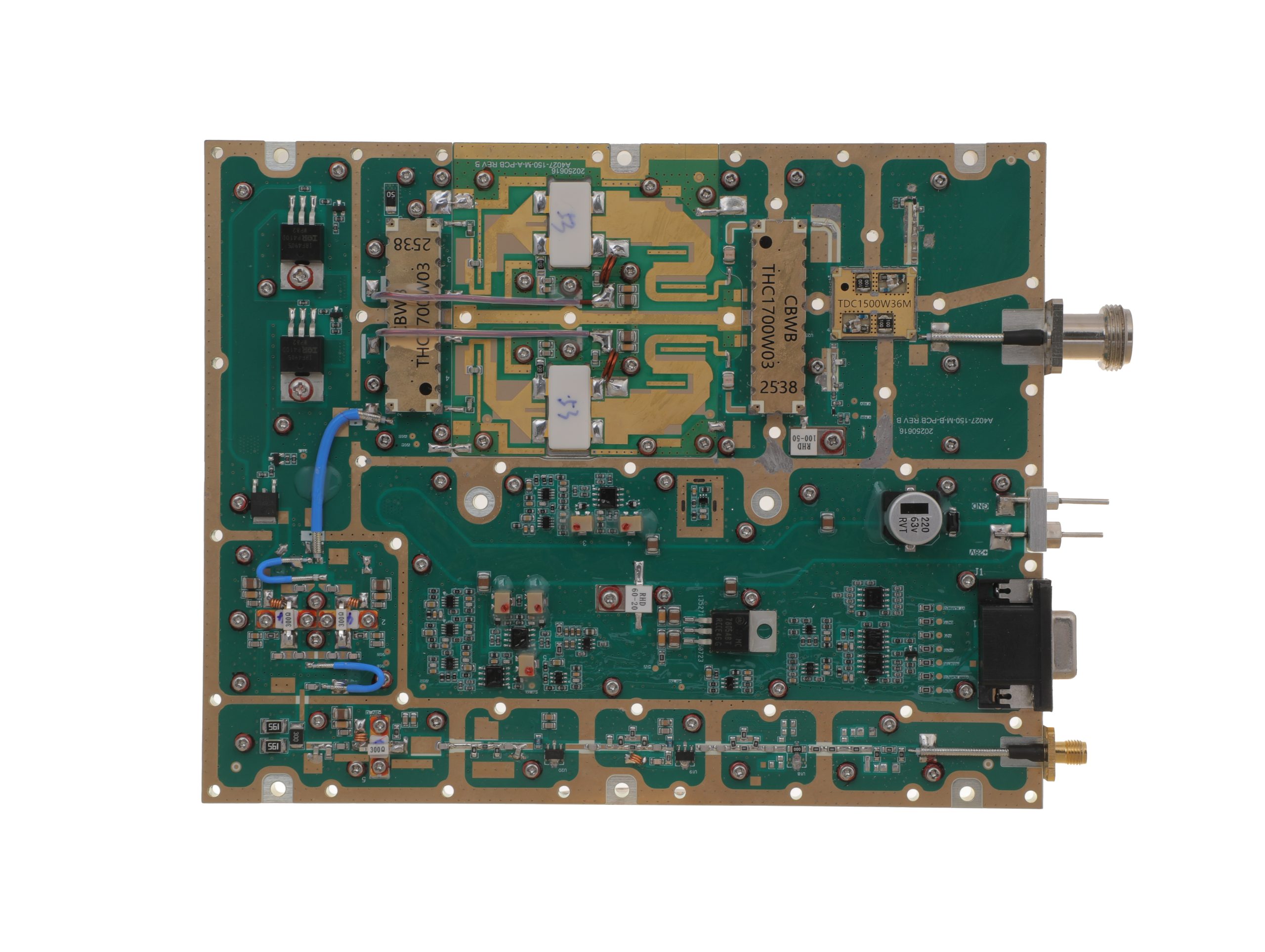 HZ3002700-100NA1Open English PDF ↗ | 80 / 100 W | 14.5 / 18 A | 200 × 158 × 25 mm | SMA-F / N-F | 15-pin D-Sub |
| 150 W | 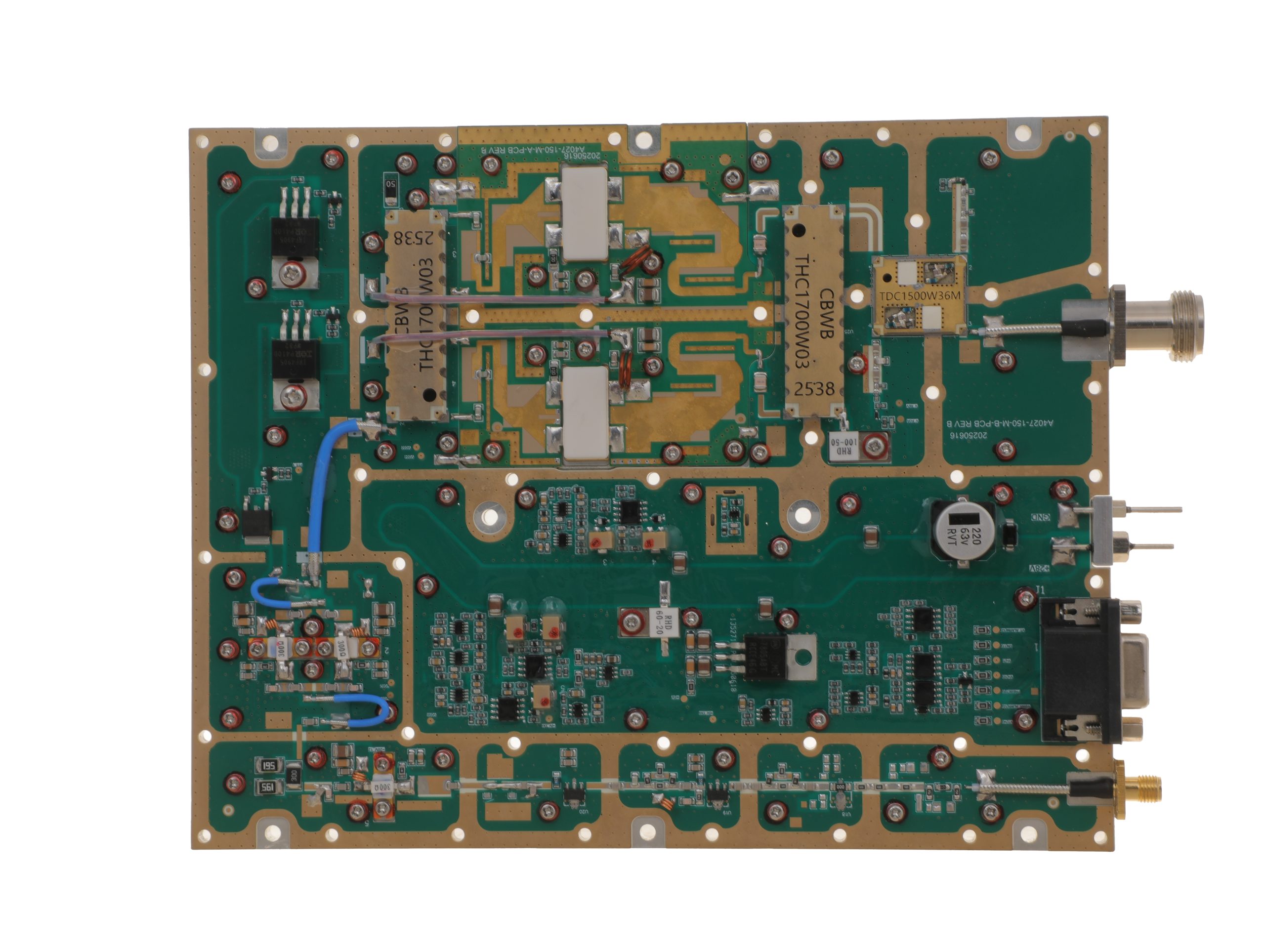 HZ3002700-150NA1Open English PDF ↗ | 120 / 150 W | 16 / 20 A | 200 × 158 × 25 mm | SMA-F / N-F | 15-pin D-Sub |
| 200 W | 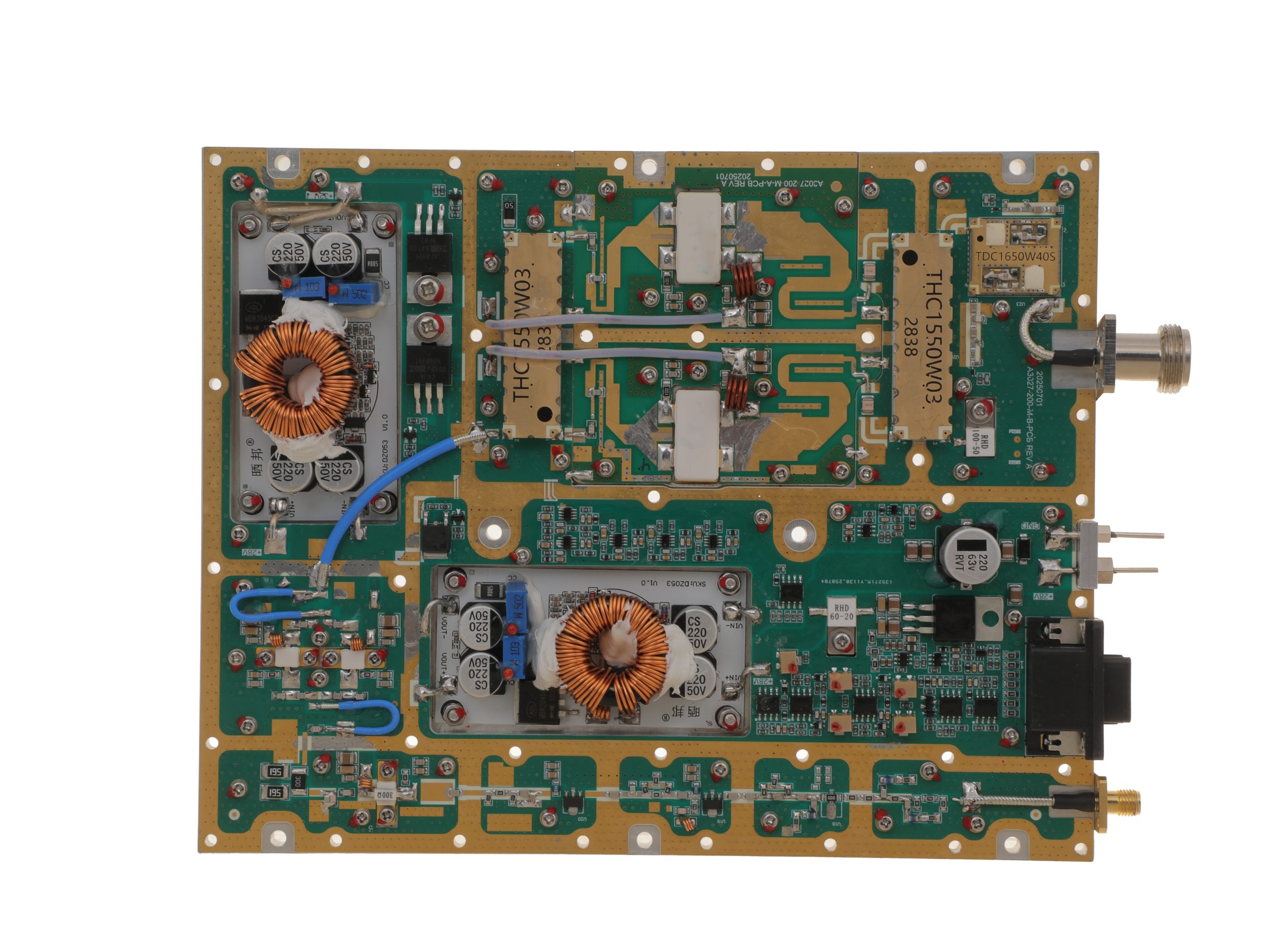 HZ3002700-200NA1Open English PDF ↗ | 160 / 200 W | 29 / 36 A | 200 × 158 × 25 mm | SMA-F / N-F | 15-pin D-Sub |
2000–6000 MHz · 5 standard models
| Power | Model / PDF | Psat min. / typ. | Current typ. / max. | Dimensions | RF input / output | Control |
|---|---|---|---|---|---|---|
| 30 W | 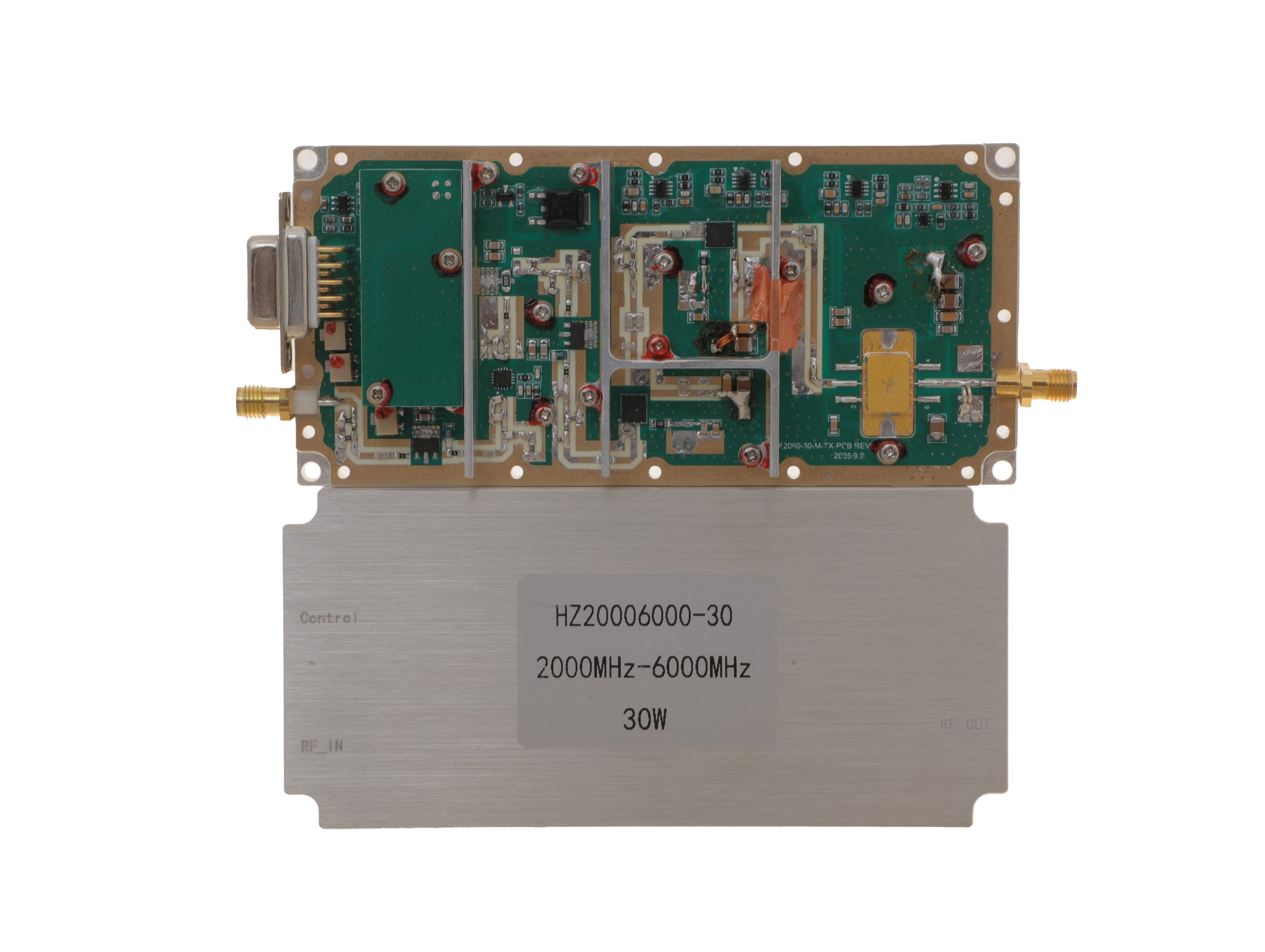 HZ20006000-30NA1Open English PDF ↗ | 25 / 30 W | 3.2 / 4 A | 125 × 59 × 21.5 mm | SMA-KFD46 / SMA-KFD46 | 9-pin D-Sub |
| 50 W | 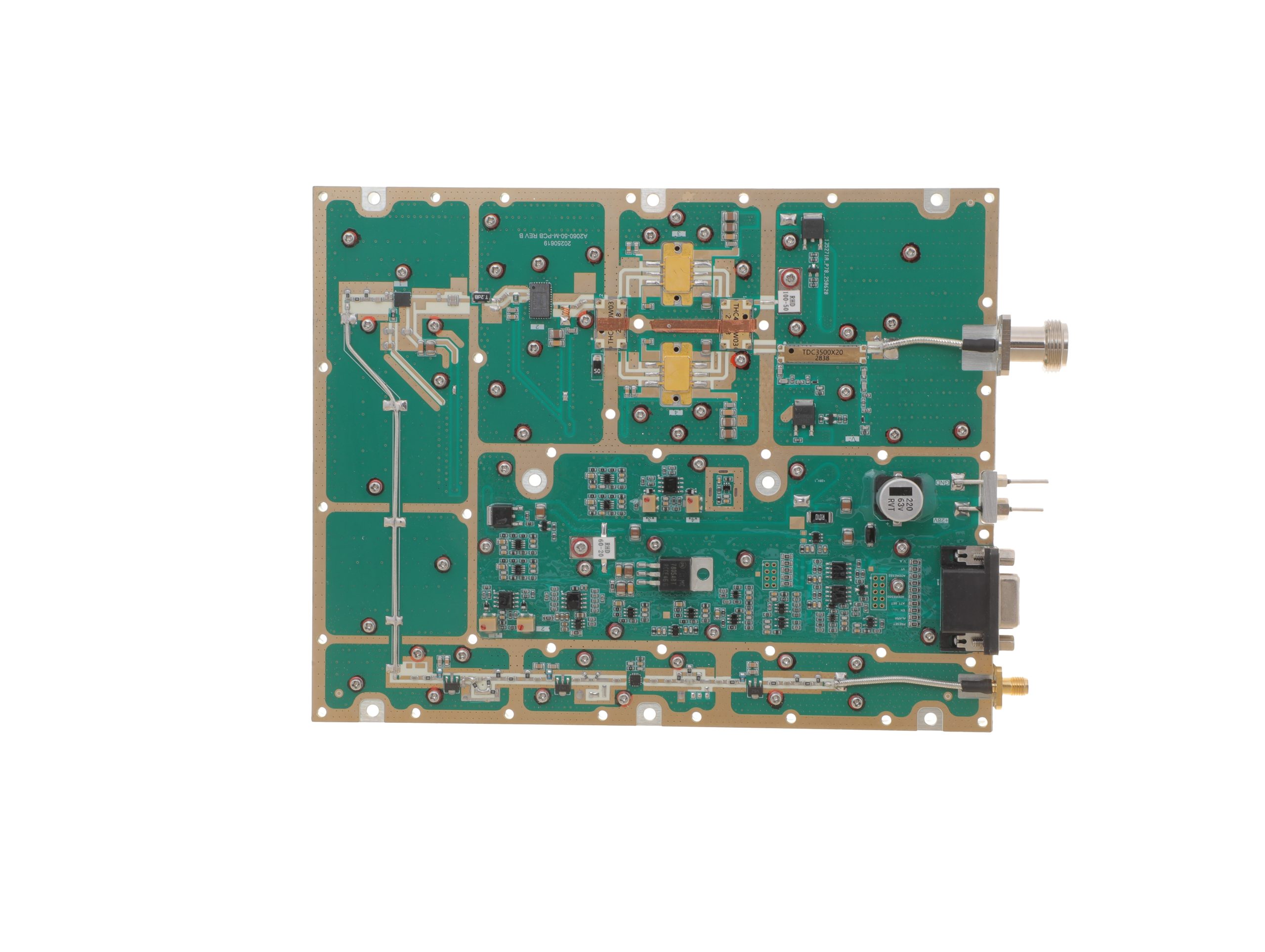 HZ20006000-50NA1Open English PDF ↗ | 40 / 50 W | 10 / 12 A | 200 × 158 × 25 mm | SMA-F / N-F | 15-pin D-Sub |
| 100 W | 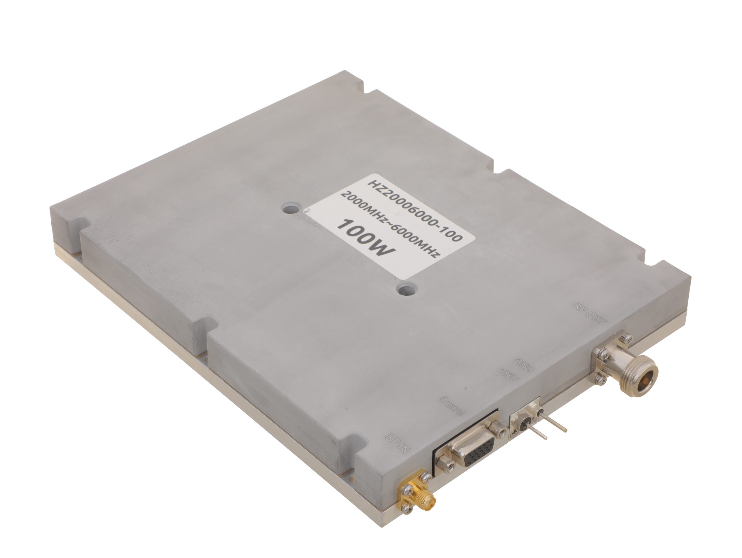 HZ20006000-100NA1Open English PDF ↗ | 80 / 100 W | 19 / 24 A | 200 × 158 × 25 mm | SMA-F / N-F | 15-pin D-Sub |
| 150 W | 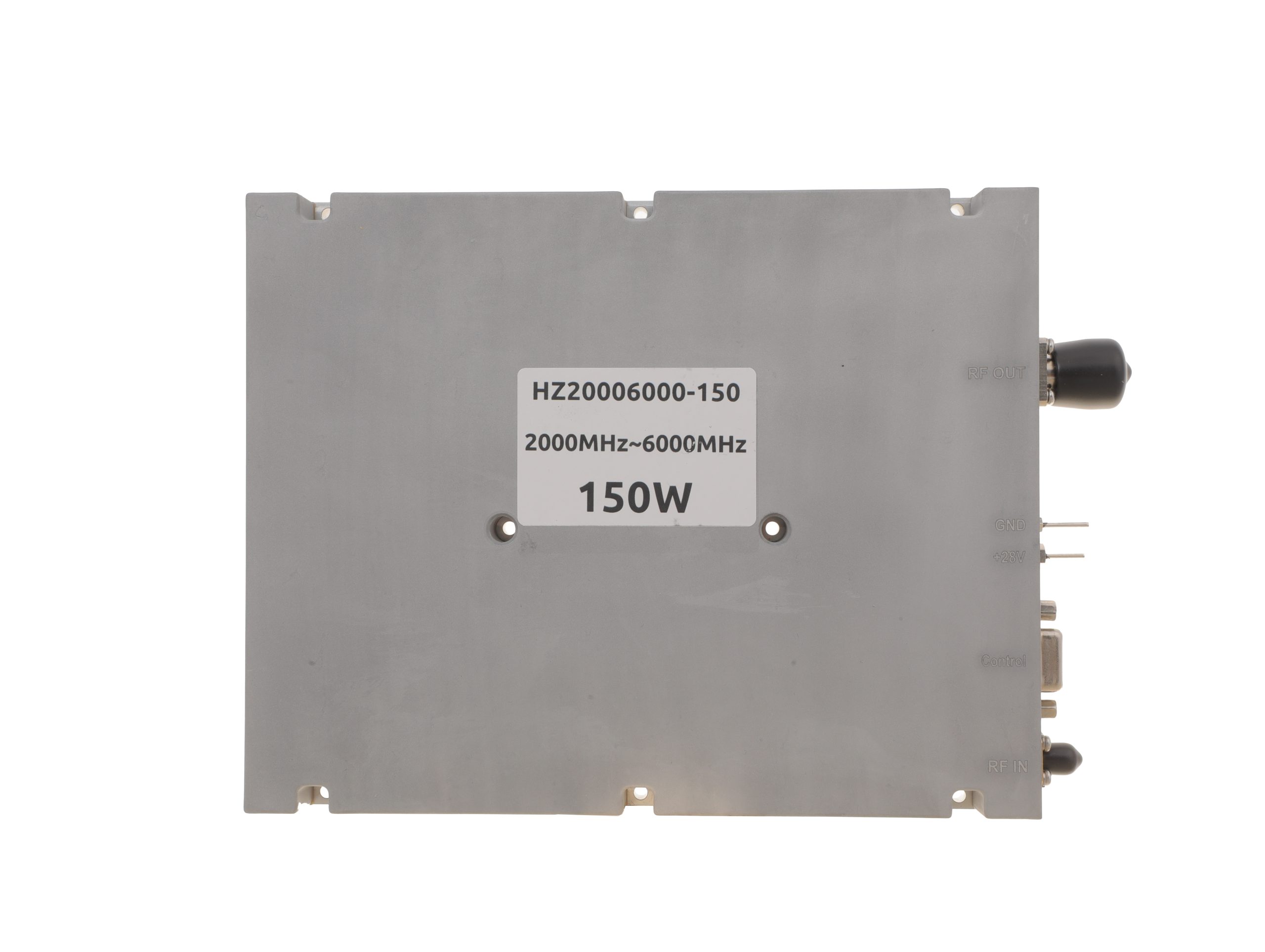 HZ20006000-150NA1Open English PDF ↗ | 120 / 150 W | 22 / 27 A | 200 × 158 × 25 mm | SMA-F / N-F | 15-pin D-Sub |
| 200 W | 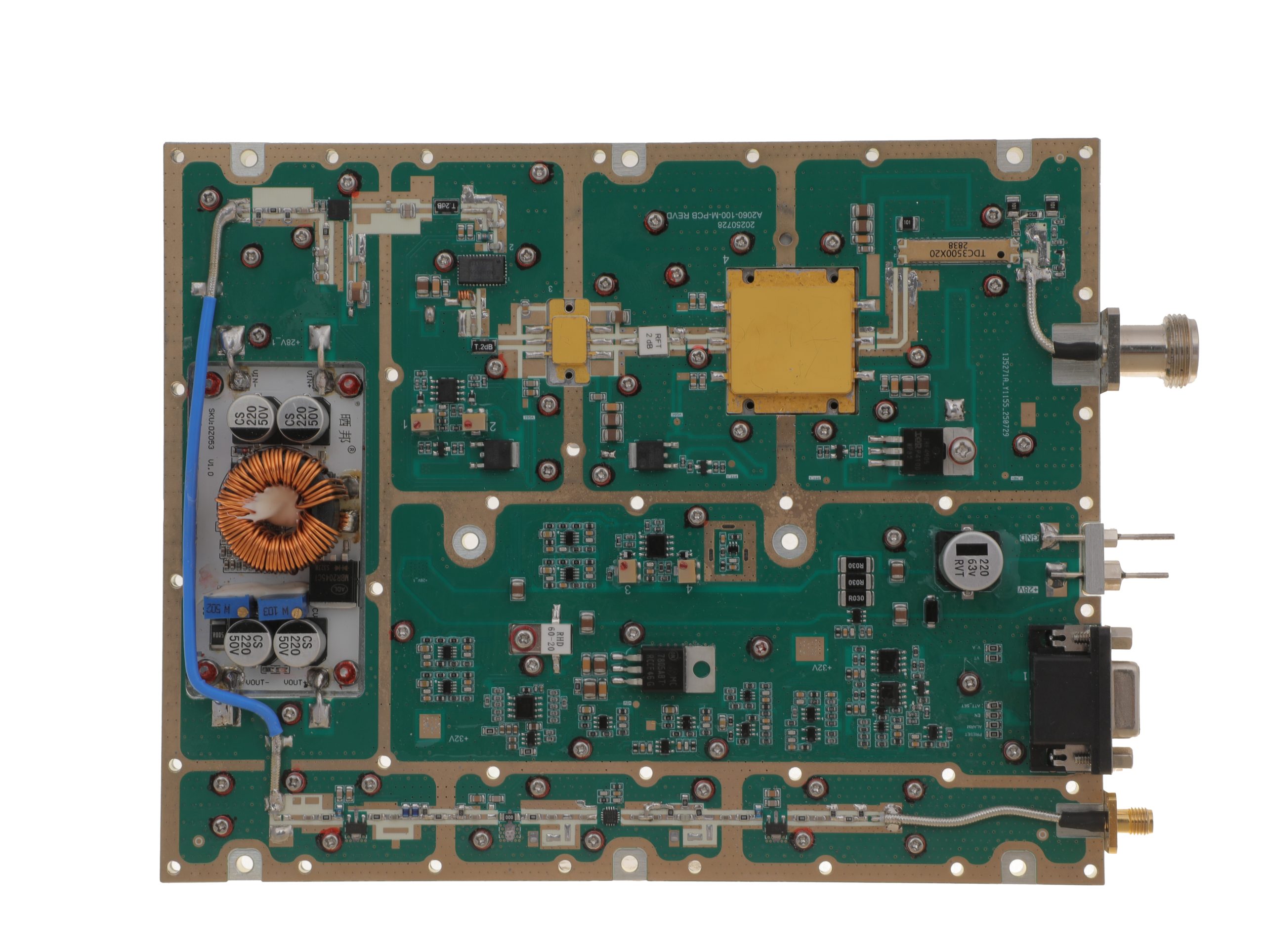 HZ20006000-200NA1Open English PDF ↗ | 160 / 200 W | 29 / 36 A | 280 × 250 × 25 mm | SMA-F / N-F | 15-pin D-Sub |
Review the applicable model’s English PDF datasheet for RF input drive, protection, and optional-function details.
Conclusion
A full-power RF PA test is long enough when the records establish the required valid interval under the approved conditions, including thermal qualification where required. The procedure must define the start, continuous or permitted cumulative holding rule, and performance limits. A total-runtime figure or stable final temperature alone cannot prove sustained full-power operation. There is no universal duration, and this review does not establish service life, untested frequency or waveform coverage, antenna-chain performance, or complete delivery acceptance.
Before accepting a duration claim in an RF amplifier test report, request the approved procedure and synchronized underlying data. Identify when the qualifying state began, mark excluded intervals, verify maintained RF and electrical limits, and write down exactly what remains unproven.
If the test conditions or reporting scope still need agreement, contact the RF SKYPOWER engineering team for a project-specific review. Provide the critical frequencies and dwell or switching sequence; target Pout and its PA-output reference plane; waveform, power metric, duty cycle, and actual Pin rule and range; and the applicable module-terminal DC limits, including nominal 28 V requirements where relevant.
Include load and reflection/VSWR limits, ambient and cooling conditions, temperature-sensor locations and stabilization criterion, required continuous or post-stabilization hold, interruption and protection rules, sampling and report format, and whether the evidence must cover a design sample, batch, or each delivered S/N. Model suitability and acceptance depend on the agreed conditions and supporting test evidence.