











An RF amplifier incoming inspection checklist should verify more than packaging and appearance. A finished module should also match its approved identity, interfaces, accompanying evidence, and a safe operating baseline before it enters system integration.
Visual checks can catch obvious shipping damage, but they cannot establish RF output, control behavior, or report traceability. A broader C-UAS RF PA acceptance checklist governs shipment-level evidence and release rules. The receiving check here has a narrower job: record the module's arrival state and decide whether it can proceed, should remain on hold, or needs an engineering review.
Any power-up or RF measurement must follow the actual module documentation and an approved test plan. Qualified personnel should define supply polarity, load, cooling, allowed input drive, instrument protection, measurement planes, and abort conditions before applying power.
1. What Visual Inspection Can and Cannot Confirm

Visual inspection confirms visible receiving conditions. It can identify crushed packaging, moisture, contamination, bent connector parts, loose hardware, damaged seals, missing accessories, label errors, and quantity discrepancies. Photograph the module and its labels before handling changes that state.
These observations do not prove that the delivered configuration matches the order. They cannot show whether control responses, static current, or RF behavior match the supplied evidence. A clean enclosure may contain the wrong revision, connector type, or pin arrangement.
The supplier's RF PA incoming-parts inspection controls components and material lots before production. Buyer-side inspection deals with a finished module after shipment. It should not recreate transistor, filter, PCB, or thermal-material release controls.
Stop before power-up if the module identity is unclear, a connector is damaged, moisture or contamination is present, or packaging suggests an uncontrolled impact. A visual pass only opens the next gate.
2. Match the Received Module to the Approved Order and Test Report
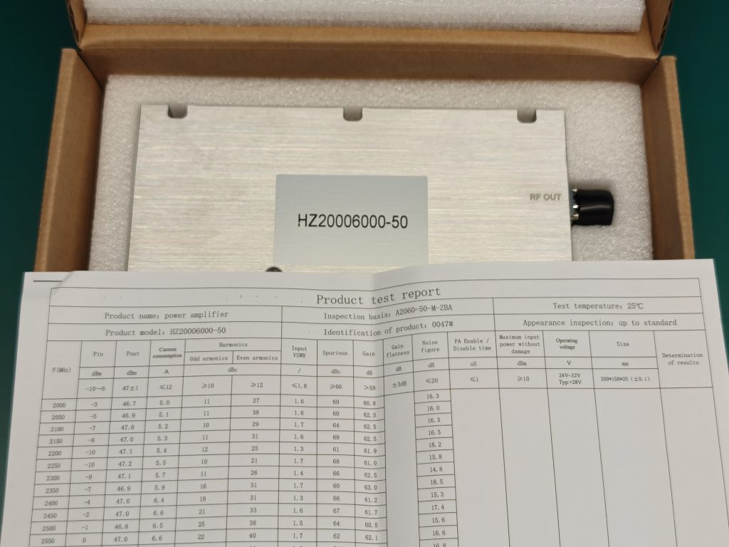
The physical module, purchase record, approved configuration, and supplied report must describe the same object or a clearly defined evidence scope. A report from another serial number cannot establish this unit's result. Likewise, a representative or batch record should remain labeled as such rather than being presented as unit-level evidence.
Record the following match before any performance check:
- Compare the model and part number with the approved order line.
- Record the module serial number exactly as marked.
- Match the hardware revision and any applicable firmware or control version.
- Confirm the report number, revision, test date, and stated release status.
- Identify whether each result applies to one unit, a batch, a configuration, or the project.
- Check that delivered cables, harnesses, adapters, and accessories match the approved configuration.
- Mark every mismatch, missing field, or unreadable identifier for review.
A traceable RF PA test evidence chain connects unit identity, test boundary, measured data, corrections, limits, and final disposition. Incoming inspection does not need to rebuild that entire chain. It does need enough of the chain to establish that the supplied evidence belongs to the received hardware.
Project contracts can define different evidence scopes. If the acceptance plan requires a unit-linked record, the serial number must connect to that dataset. If an approved batch or configuration record is sufficient, do not relabel it as a per-unit report. Hold the receiving decision whenever model, serial number, revision, or evidence scope cannot be reconciled.
3. Check RF, DC, Control, Cooling, and Mechanical Interfaces Before Power-On
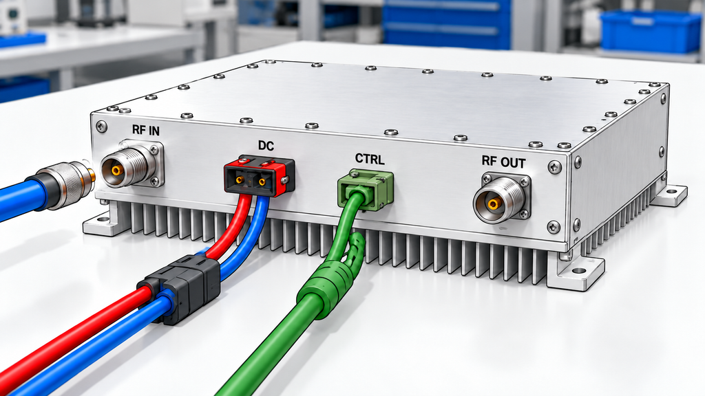
Interface inspection asks whether the received module can be connected under its approved boundaries, not whether a plug appears to fit. Check RF input and output connector types, DC connector identity and polarity, control and alarm ports, mounting surfaces, cooling interfaces, mechanical envelope, and supplied harnesses against current module documents.
DC input connector details for C-UAS RF PA modules matter because similar-looking connectors can carry different pin assignments, current limits, or mechanical keys. Do not infer pinout, polarity, supply range, or torque from another model. Record the exact document revision used for the check.
Cooling and mounting need the same discipline. A bare module may require a defined heatsink, cold plate, airflow path, or mounting contact before a powered test. Record that boundary, and never treat a brief cold-state run as stabilized thermal evidence.
Do not proceed when supply polarity, pin assignment, RF load, cooling, allowed operating state, or mechanical fit remains unknown. Resolving that uncertainty before connection prevents an invalid test from becoming a damaged module or a misleading failure record.
4. Establish a No-RF DC and Control Baseline
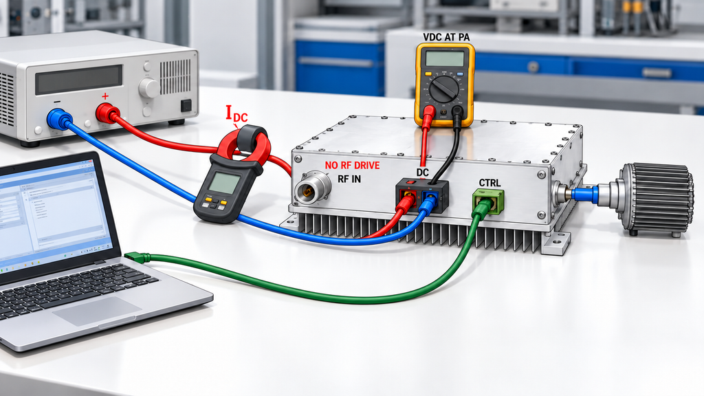
A no-RF baseline checks whether the module reaches its expected static electrical and control state before RF drive. The approved procedure should define supply connection, enable state, cooling, measurement point, current boundary, communication method, and abort conditions. No universal sequence replaces it.
The test engineer should record voltage at the defined module power terminals where required, static current, enable status, communication response, address or identity response, alarm state, and any unexpected temperature rise, odor, sound, or indication. A power-supply display does not automatically equal voltage at the PA terminals, especially when the harness carries substantial current.
Normal static behavior does not prove protection performance. It only shows that protection did not trigger under that no-RF condition. Full RF PA protection logic acceptance has to define the trigger, response, status visibility, reset, recovery, and repeatability for each required fault state.
Pause the inspection if current, communication, control state, alarm identity, or temperature behavior conflicts with the approved document or supplied baseline. Preserve the observed state rather than repeatedly cycling power until the symptom disappears.
5. Run a Safe RF Baseline Under Defined Conditions
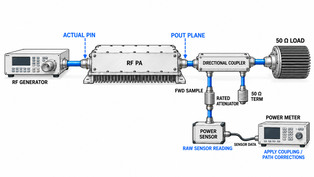
An RF baseline is useful only when the team can explain what was applied, where it was measured, and what the result represents. It is not a universal full-power test. The approved plan should define frequency, waveform, Actual Pin, output measurement plane, load, supply, cooling, duration, instrument ratings, and stop limits.
The signal-generator setting is not automatically Actual Pin. Source cables, attenuators, switches, drivers, fixtures, mismatch, and calibration offsets can change power reaching the PA input. The actual RF PA input-power check should establish that boundary before a power result is interpreted.
Record raw instrument results and any approved path correction separately. A corrected Pout value should name its reference plane. One reading at one frequency and thermal state cannot establish full-band, stabilized, long-duration, or batch performance. If the test boundary supports only a low-level or short baseline, state that scope plainly.
A difference from the factory report is not immediate proof of damage. First determine whether unit identity, frequency, waveform, Actual Pin, Pout reference plane, load, Vdc, cooling, thermal state, meter settings, and corrections are sufficiently aligned. Persistent differences belong in a controlled factory and customer RF PA power retest, not in an improvised arrival test.
Stop when the load, attenuation, instrument protection, cooling, allowed Pin, reference plane, or abort boundary is unknown. A documented "not tested" or "not comparable yet" result is safer than a number produced under an uncontrolled setup.
6. Record ACCEPT, HOLD, or ESCALATE Before System Integration
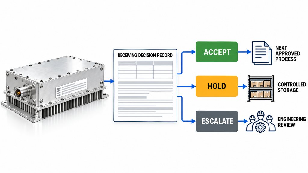
The receiving record should end with an explicit next action. The labels below are a practical framework rather than universal contract terms. Each project should define who has authority to accept a module, place it on hold, or escalate a discrepancy.
| Inspection gate | Evidence to review | What it can establish | HOLD or ESCALATE trigger | Next action |
|---|---|---|---|---|
| Visible condition | Packaging, photographs, labels, connectors, accessories | Visible shipping state and obvious identity errors | Damage, moisture, contamination, missing parts, or unreadable identity | Isolate the module and document the condition |
| Identity and report match | Order line, model, part number, S/N, versions, report scope | Whether hardware and evidence refer to the approved object | Model, S/N, version, or evidence-scope mismatch | Request corrected records or engineering disposition |
| Interface readiness | RF, DC, control, cooling, mounting, and harness documents | Whether connection boundaries are known | Unknown polarity, pinout, load, cooling, rating, or mechanical fit | Keep power off until the boundary is confirmed |
| No-RF baseline | Defined supply point, static current, control state, alarms, temperature observations | Static electrical and control behavior under the recorded condition | Unexplained current, status, communication, alarm, or heating behavior | Preserve evidence and escalate before RF drive |
| RF baseline | Frequency, waveform, Actual Pin, Pout plane, load, Vdc/Idc, cooling, instruments, duration | Limited RF behavior under one defined setup | Unsafe setup, missing boundary, non-comparable result, or unexplained deviation | Stop, align conditions, or plan a controlled retest |
| Final receiving record | All prior evidence, open differences, owner, date, disposition | Whether the module may enter the next project process | Any unresolved identity, safety, or evidence conflict | Mark ACCEPT, HOLD, or ESCALATE under project authority |
ACCEPT allows movement into the next approved process; it does not mean system integration or full contractual acceptance has passed. HOLD preserves the module while a defined gap is resolved. ESCALATE sends a documented discrepancy to its responsible reviewer without assuming a root cause.
If the inspection shows that the delivered configuration cannot meet the approved requirement, the RF power amplifier module families provide a starting point for a new requirement-based evaluation. That route does not establish project suitability or recommend a specific model.
Conclusion: Build an Arrival Baseline Before Installation
Visual inspection can release only the visible receiving condition. A defensible arrival baseline also needs matching hardware and evidence, confirmed interfaces, an explainable no-RF state, and any RF spot check performed under defined, safe conditions.
That baseline can decide whether the module enters the next approved process, remains on hold, or needs deeper review. It cannot set model-specific voltage, drive, load, cooling, protection, or acceptance limits, and it cannot replace full shipment acceptance or installed-system verification. One convenient RF reading should never be treated as complete performance approval.
Before contacting a supplier, preserve the module identity, photographs, report references, interface documents, observed DC and control state, RF test conditions, raw and corrected results, and every unresolved difference. If those records still leave the arrival status unclear, contact the RF engineering team with the model, S/N, versions, frequency, waveform, Pin and Pout reference planes, DC supply, load, cooling, control interface, discrepancy, and required evidence scope for a bounded engineering review.