











An RF amplifier compression thermal test must include the project-defined thermally stabilized state because a cold-state Pin–Pout curve and P1dB boundary describe only that recorded cold condition and cannot establish the stabilized-state boundary; a meaningful cold-to-hot comparison also requires both states to use traceable, comparable conditions. Measure a separate Pin–Pout curve for each state, establish each curve’s linear-gain reference, and report Pin1dB, the input power at the 1 dB compression point, and Pout1dB, the corresponding output power, separately. Without aligned reference planes—the declared points in the RF path where Pin and Pout are defined—operating conditions, calibration records, and an uncertainty assessment, a difference remains an observation rather than proof that temperature caused a change. The project must also define what “cold” and “thermally stabilized” mean; elapsed time alone cannot establish either state. The first step is to document those state definitions before comparing curves.
1. Define the Cold and Thermally Stabilized States
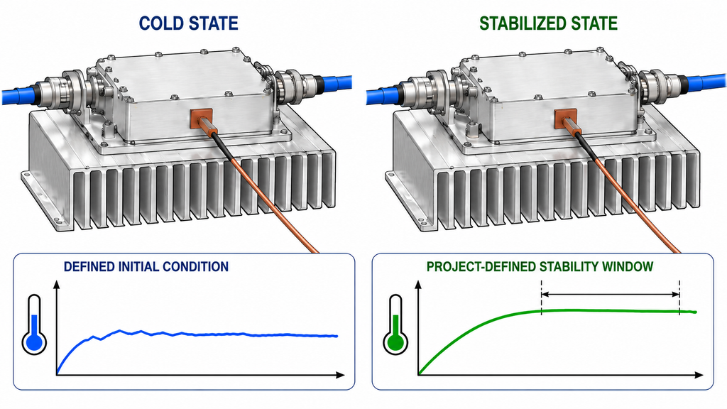
“Cold” and “thermally stabilized” are test states, not universal temperature labels. The project test procedure should define the starting condition for the cold measurement and the criterion used for a stabilized measurement. That definition may refer to specified temperature observations, operating conditions, or an agreed stability rule. Record the relevant measurement points, state, and time with each curve so another engineer can tell which condition produced each result.
A period of operation by itself does not prove that the amplifier reached a stable thermal state. The equipment, cooling arrangement, load, waveform, and ambient conditions can affect how a given setup behaves. This article does not set a soak duration, a temperature threshold, or a universal drift limit. Those values belong in the applicable project procedure. A project-defined thermal-soak boundary should state the conditions used to judge RF PA power after thermal soak, but that hot-state Pout check does not replace the paired P1dB comparison here.
For each state, record:
- The project’s cold-state definition and initial operating condition.
- The project’s thermal-stability criterion and the observations used to apply it.
- Temperature measurement locations, recorded values, and timestamps.
- Any state or operating information needed to identify the corresponding Pin–Pout curve.
If the state definition, relevant temperature observation, or stability criterion is missing, report the state as incomplete. Do not attribute a boundary difference to temperature until both labels correspond to documented conditions. The buyer’s next action is to identify the project procedure and mark each undefined state field for resolution.
2. Match the Conditions That Shape Each Pin–Pout Curve
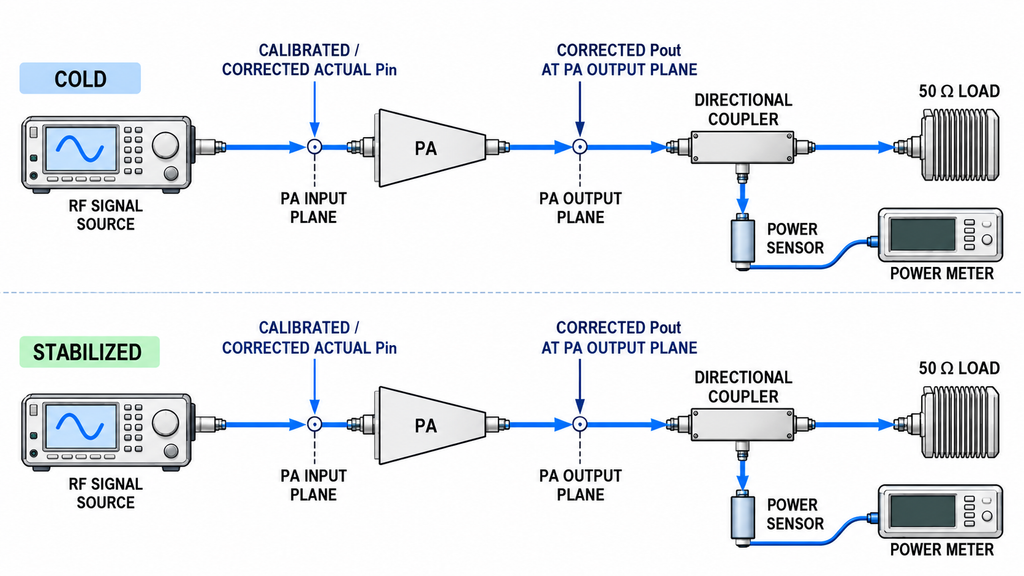
A curve difference can reflect a changed test setup as well as a changed thermal state. Before comparing compression boundaries, confirm that each curve represents the same project measurement at the same defined frequency and uses matched or traceably corrected conditions. A condition that changes between runs must be recorded with its correction basis; an unquantified difference limits comparability.
Check the variables that can change the measured curve or its interpretation:
- Frequency and signal definition, including waveform and duty cycle where applicable.
- Bias and supply conditions, load, cooling configuration, and relevant ambient conditions.
- Pin reference plane at the PA input and Pout reference plane at the PA output.
- Calibration state, source- and output-path corrections, instrument configuration, and measurement status.
- Sweep procedure, input-power increments, gain calculation, and treatment of the measured signal.
A generator setting does not, by itself, establish Actual Pin at the PA input reference plane. The source path may require calibration or documented correction. Likewise, an output reading should not be described as a PA-output result unless its reference plane and correction chain support that description. A defensible pre-test RF PA input-power measurement therefore identifies the PA input reference plane and applicable source-path correction without substituting a generator display value.
Build a two-state condition record before deciding whether the curves can be compared. Mark every item as matched, corrected with a traceable basis, unmatched, or unknown. Do not fill a missing field from memory or assume that a displayed instrument setting already includes the applicable path correction. If reference planes differ, waveform or load changes remain unquantified, or the calibration chain cannot be traced, stop direct comparison and request the missing setup records.
3. Measure Paired Pin–Pout Curves and Locate Each P1dB Boundary
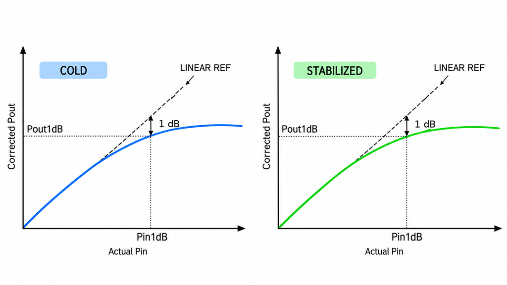
Measure both states using the same project-defined procedure. For each curve, establish the linear-gain reference from its linear operating region, then compare measured gain with that reference as input power changes. The P1dB point occurs where gain has fallen by one decibel relative to the applicable linear reference. The input power at that point is Pin1dB; the corresponding output power is Pout1dB. These are related but distinct measurements, so a report that gives only “P1dB” without saying which value it means leaves the boundary ambiguous.
Retain the underlying Pin, Pout, and gain data for each state, along with the reference used to locate the compression point. Use the same controlled input-power increments, signal definition, fundamental-component definition and harmonic treatment, resolution near the crossing, correction method, and calculation approach for both curves. Keep each pair at the same specified frequency and waveform; do not combine different frequencies or waveforms in one difference, and identify any method change separately. The report should make the linear reference and the identified one-decibel crossing reviewable. It should also preserve the conditions and state labels attached to each dataset.
A boundary is not established merely because a summary reports a value. If the linear region is inadequate, the sweep does not cover the crossing, the data resolution cannot locate it, or overload or protection behavior affects the measurement, mark that boundary as unavailable or invalid under the project method. Do not estimate a missing crossing or substitute a saturation value; Psat and P1dB describe different boundaries. A specified-frequency P1dB pair does not establish the frequency coverage required in a full-power RF PA sweep test; do not present it as full-band performance.
4. Judge Whether the Observed Boundary Difference Is Comparable
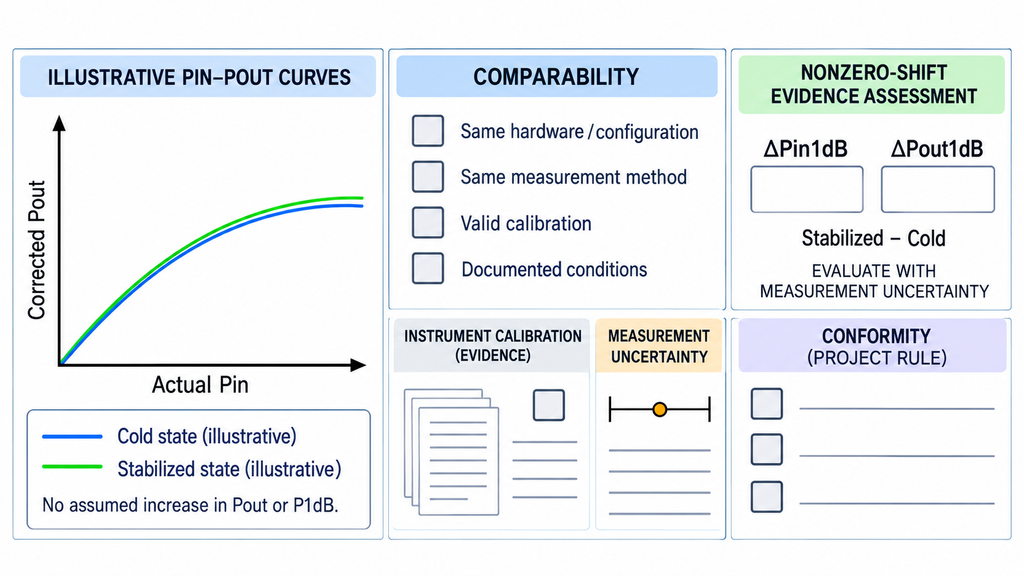
A difference becomes interpretable only after the state and measurement conditions pass the matching review. Report a signed difference for each metric using one declared convention, such as stabilized-hot minus cold. Keep the Pin1dB difference separate from the Pout1dB difference. A shift in one does not automatically describe the shift in the other, and neither value alone identifies a thermal cause.
Then evaluate three separate questions. First, do matched or traceably corrected conditions support treating the paired results as comparable? Second, does the signed difference, with the applicable RF PA measurement uncertainty, support the project-defined criterion for claiming a nonzero boundary change? Third, does the result conform to the project limit under its written decision rule, including any required treatment of uncertainty? These questions are independent: a result that does not demonstrate a nonzero shift can still be assessed for conformity when the project limit and decision rule support that assessment. A method article cannot supply a universal P1dB drift direction, tolerance, pass threshold, or decision rule. The project must provide its limit, decision rule, and source. Hot-state small-signal gain is also a separate metric from a compression boundary and must not be substituted for Pin1dB or Pout1dB.
Classify the result as comparable only when key conditions are aligned or traceably corrected and uncertainty supports the stated interpretation. A partially comparable result must identify which observations remain supportable and which conditions limit the conclusion. If the calibration or matching basis is missing, stop the comparison and request the missing records or repeat the measurement under aligned conditions. If comparable data do not satisfy the project-defined criterion for demonstrating a nonzero change, report that no nonzero shift was demonstrated; do not turn that finding into an automatic conformity decision. Apply pass/fail only through the project limit, the applicable uncertainty, and the written decision rule. If any of those inputs is missing or the evidence is insufficient to apply that rule, withhold the conformity conclusion. “Not comparable yet” and “no nonzero shift demonstrated” do not mean that the product or supplier failed.
Use the record below to keep both state definitions, the two P1dB metrics, and three separate outputs together: comparability, evidence for a nonzero boundary change, and conformity under the written project decision rule. Enter project measurements, limits, and decision-rule sources; mark unavailable inputs “Not provided.”
| State | Temperature / stability criterion | Frequency | Waveform / duty cycle | Bias / supply | Load / cooling | Pin plane / calibration | Pout plane / correction | Linear-gain reference | Pin1dB | Pout1dB | Cold-to-hot difference | Measurement uncertainty | Nonzero-shift evidence conclusion | Comparability status | Project limit | Written decision-rule source | Conformity conclusion | Result limits |
|---|---|---|---|---|---|---|---|---|---|---|---|---|---|---|---|---|---|---|
| Cold | Not provided | Not provided | Not provided | Not provided | Not provided | Not provided | Not provided | Not provided | Not provided | Not provided | Not provided | Not provided | Not assessed; paired data not provided | Not assessed; paired data not provided | Not provided | Not provided | Not assessed; project rule not provided | No result supplied |
| Thermally stabilized | Not provided | Not provided | Not provided | Not provided | Not provided | Not provided | Not provided | Not provided | Not provided | Not provided | Not provided | Not provided | Not assessed; paired data not provided | Not assessed; paired data not provided | Not provided | Not provided | Not assessed; project rule not provided | No result supplied |
The table is a reporting record, not a substitute for the raw curves or the project’s acceptance criteria. A nonzero-shift conclusion and a conformity conclusion are separate. If a field needed for comparability remains unknown, do not compare the states. If the project limit, applicable uncertainty, or written decision rule is absent, keep conformity “Not assessed.”
RFQ: What to specify for a cold-to-hot P1dB comparison
An RFQ should tell each supplier what measurement would answer the project’s question and what evidence must accompany the result. Define the project’s values; do not ask suppliers to adopt an unstated universal condition or promise a generic cold-to-hot difference. Include the following inputs where they apply:
- Test frequency, waveform, duty cycle, bias and supply conditions.
- Load, cooling arrangement, and the project definitions for cold and thermally stabilized states.
- Pin and Pout reference planes, calibration status, and source- or output-path corrections.
- Sweep and calculation rules, including the linear-gain reference and reporting of Pin1dB and Pout1dB separately.
- Original paired curves, uncertainty treatment, project acceptance limit, written decision rule, and the source of each.
- A report and both original state curves bound to the same tested unit or serial number, with the test date, method version, calibration status, report revision, and any deviations or missing data; define the repeat-test rule in the RFQ rather than treating this record as an existing supplier commitment.
Ask the supplier to identify any condition that differs from the request and explain how that difference affects comparison. If the project has not defined a thermal-stability criterion, acceptance limit, applicable uncertainty treatment, or written decision rule, resolve those inputs before requesting a pass/fail commitment. The request should produce reviewable evidence, not imply that a supplier has already achieved an unprovided result.
Conclusion
RF PA compression should be checked at the project-defined thermally stabilized state because a cold-state Pin–Pout curve and P1dB boundary describe only the recorded cold condition and cannot establish the stabilized-state boundary; cold and stabilized boundaries can then be compared when both states are defined, the relevant measurement conditions and reference planes are aligned or traceably corrected, and uncertainty supports interpretation. Report Pin1dB and Pout1dB separately. Then record three distinct conclusions: whether the results are comparable, whether the evidence supports a nonzero boundary change, and whether the result conforms under the project limit and written decision rule. A measured difference alone does not prove that temperature caused the change, while failure to demonstrate a nonzero shift does not by itself decide conformity. This comparison does not prescribe a universal shift direction or magnitude, stabilization duration, acceptance threshold, or decision rule; those conclusions require the applicable unit data and project procedure.
Before making a supplier decision, use the completed paired record to decide whether the result is comparable. If it is comparable, state separately whether a nonzero shift was demonstrated and whether the result conforms under the cited project decision rule. Request missing evidence or repeat the test when comparability cannot be established; withhold conformity when the project limit, applicable uncertainty, or written decision rule is missing or the evidence is insufficient to apply that rule. Do not convert any of those gaps into a product-failure finding. The resulting paired record should sit within the broader evidence set defined by the C-UAS RF PA acceptance checklist.
If project boundaries or evidence requirements still need clarification after that review, contact the RF engineering team for a project-specific discussion.