










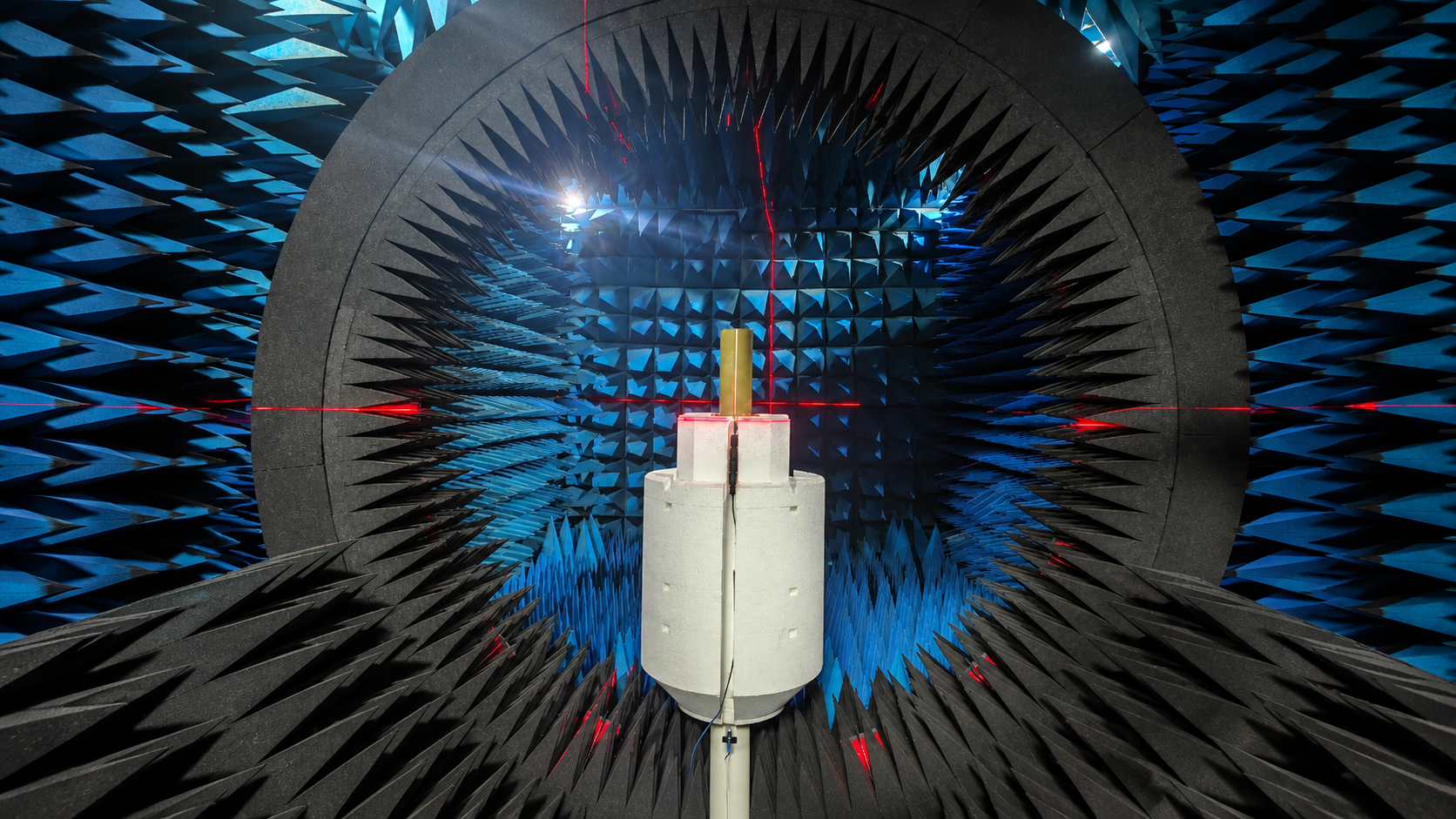
Choosing the right EMC test equipment starts with the tests your laboratory must perform. The instruments, interfaces, facilities, and verification records must support those tests as one system.
Electromagnetic compatibility (EMC) testing covers different tasks. Equipment used to measure unwanted emissions serves a different purpose from equipment used to generate immunity disturbances. Instruments designed for the same test may also differ in their measurement capabilities, interfaces, software support, and calibration requirements.
A laboratory can own capable instruments and still be unable to run its planned tests. Missing coupling devices, incompatible software, unsuitable facilities, or incomplete verification records can prevent the system from being used as planned.
1. What EMC Tests Will Your Lab Need to Perform?
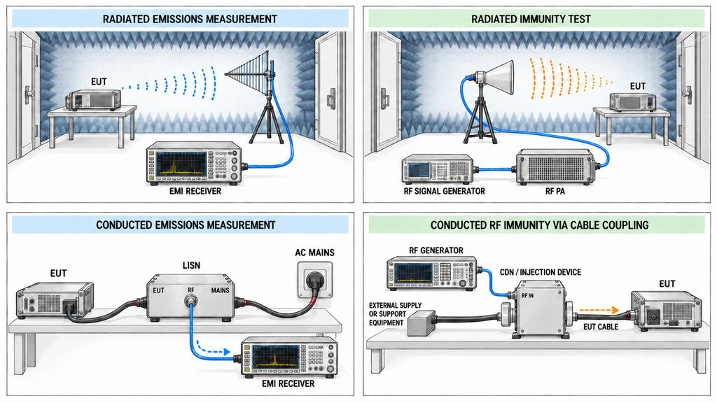
Start by defining what the laboratory will test and why.
An engineering team investigating interference during product development may need flexible diagnostic equipment. A precompliance laboratory needs repeatable measurements that help identify problems before formal testing. A laboratory performing tests against specified requirements needs instruments, procedures, and facilities suited to those methods.
These purposes may overlap, but they do not require identical equipment.
EMC testing generally covers emissions and immunity.
Emissions testing measures unwanted electromagnetic disturbances produced by electrical or electronic equipment. Depending on the product and test method, measurements may involve radiated emissions, conducted emissions, or both.
Immunity testing evaluates how equipment behaves when exposed to defined electromagnetic disturbances. Depending on the applicable requirements, these may include radiated RF fields, conducted RF disturbances, electrostatic discharge, electrical fast transients, and surge events.
For example, IEC 61000-4-3 addresses radiated RF immunity, while IEC 61000-4-6 addresses immunity to RF disturbances coupled through conductors. Their equipment arrangements and verification methods differ.
The applicable product requirements and test plan determine which methods the laboratory must support. Do not use a general EMC standard to assign test levels or acceptance criteria to every product.
Define the laboratory’s actual capability requirements
Before selecting equipment, establish the product families, intended markets, applicable standards or contractual requirements, and test methods.
The equipment under test (EUT) also matters. Its power supply, connected cables, communication interfaces, operating modes, and monitoring requirements can affect the test arrangement.
The laboratory should document the intended test conditions and identify who is responsible for defining and evaluating the EUT acceptance criteria.
Next, review the equipment already available.
An existing receiver may be suitable for development diagnostics but lack the measurement functions or supporting facilities required for another test. An existing RF amplifier may cover the intended frequencies while still requiring verification of its linear operating capability and compatibility with the proposed antenna path.
During a laboratory upgrade, the buyer may need accessories, software, or verification services rather than another instrument.
Record the required test capabilities, reusable instruments, missing functions, and unresolved conditions before shortlisting equipment.
If the intended tests, applicable requirements, or EUT operating conditions are still undefined, hold the equipment scope until those inputs are resolved.
2. What EMC Test Equipment Does Each Test Require?
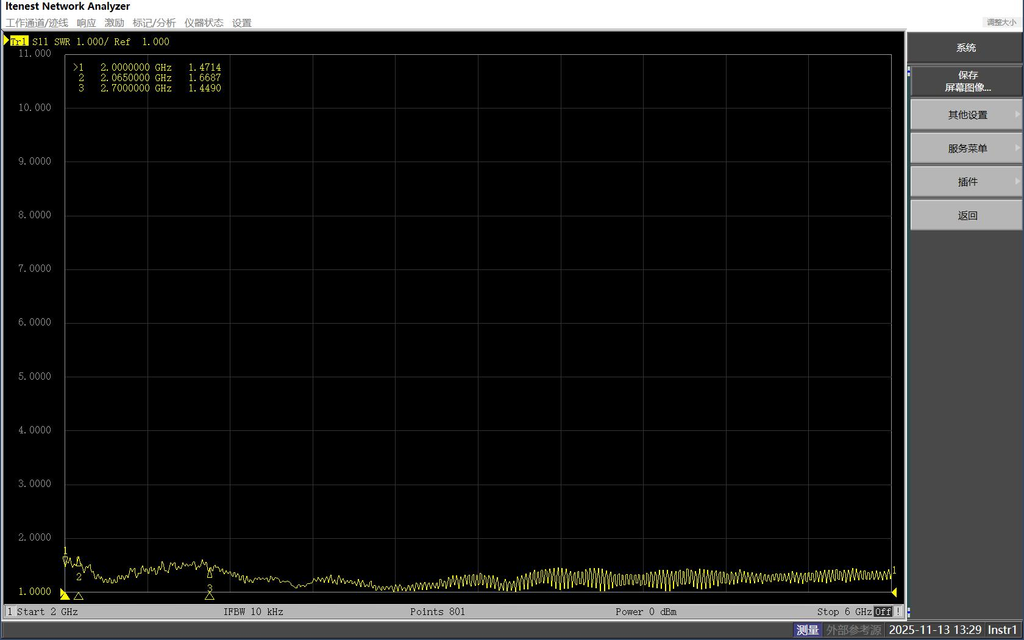
Match each required test method to the equipment functions it needs.
A complete configuration may include measurement instruments, signal sources, amplifiers, antennas, probes, coupling devices, control software, and laboratory facilities. Some instruments combine several functions in one enclosure.
Selection should therefore focus on the required functions and their operating conditions rather than the number of separate instruments.
EMC test types and equipment functions
The following table provides a starting point for equipment planning. It describes typical functions, not a fixed purchasing package for every laboratory.
| EMC test category | Typical equipment functions | Key selection or interface question | Applicable method and project conditions |
|---|---|---|---|
| Radiated emissions | EMI test receiver or suitable measurement instrument, receiving antenna, cables, site accessories, measurement software | Do the measurement range, detector functions, antenna factors, site conditions, and correction data support the intended method? | Applicable emissions requirements, measurement configuration, site, and EUT operating conditions |
| Conducted emissions | EMI receiver, line impedance stabilization network or other specified measurement network, suitable cables and protection | Does the measurement network match the relevant port, and can the receiver support the required measurement conditions? | Applicable conducted-emissions method, port type, power arrangement, and measurement requirements |
| Radiated RF immunity | RF signal generator, power amplifier, transmitting antenna, directional power measurement, field probe, control and monitoring functions | Can the installed RF chain generate and verify the required field under the specified conditions? | IEC 61000-4-3 or other applicable radiated-immunity requirements |
| Conducted RF immunity | RF source, suitable amplifier, specified coupling or injection devices, measurement and verification accessories, EUT monitoring | Does the coupling method match the EUT interfaces and the required verification procedure? | IEC 61000-4-6 or other applicable conducted-immunity requirements |
| Electrostatic discharge | ESD simulator, specified discharge accessories, test arrangement, and EUT monitoring | Does the simulator support the required discharge method, and is the relevant verification evidence available? | IEC 61000-4-2 where applicable, plus product-specific requirements |
| Electrical fast transient/burst | EFT/burst generator, appropriate coupling or decoupling network or clamp, monitoring functions | Can the disturbance be applied to the specified ports using the required coupling arrangement? | IEC 61000-4-4 where applicable, plus port and test conditions |
| Surge immunity | Suitable surge generator, coupling and decoupling functions, protection and monitoring arrangements | Does the generator and coupling arrangement support the required waveform, port configuration, and test method? | IEC 61000-4-5 where applicable, plus project-specific requirements |
A near-field EMI probe used to investigate interference on a circuit board is not interchangeable with a calibrated field probe used during radiated-immunity field verification.
A receiving antenna used for emissions measurements and a transmitting antenna used for radiated RF immunity also serve different functions. Evaluate each antenna’s electrical characteristics and verification needs for its assigned role.
Similarly, the measurement network used for conducted emissions cannot automatically replace a coupling and decoupling device specified for conducted immunity.
For antenna screening, compare measured electrical characteristics at the intended frequencies. RF SKYPOWER’s broadband antenna range includes 300–2700 MHz horn antenna data and 2000–6000 MHz horn antenna data. Those documents show antenna parameters and test results; the intended EMC installation still needs verification under its applicable method.
Precompliance and formal test capability
Precompliance equipment can help engineers identify problems before more demanding testing. It is particularly useful during design development and troubleshooting.
However, a spectrum analyzer used for precompliance measurements does not automatically meet the requirements for formal emissions measurements. Check its detector functions, bandwidths, accuracy, correction data, and other relevant capabilities against the intended method and CISPR 16-1-1, where applicable.
Apply the same method-specific checks to antennas, test sites, and accessories. Development equipment may still fall short of a specified test procedure.
Check the control and monitoring functions as well. Depending on the method, the laboratory may need to coordinate signal generation, measurement, instrument corrections, EUT operating modes, and test records.
Integrated hardware and software may cover several functions. Check what the supplied configuration actually supports.
For each test function, identify the instrument or combination that will provide it. Resolve missing functions before final model selection.
3. How Do You Select and Match the RF Test Equipment Chain?
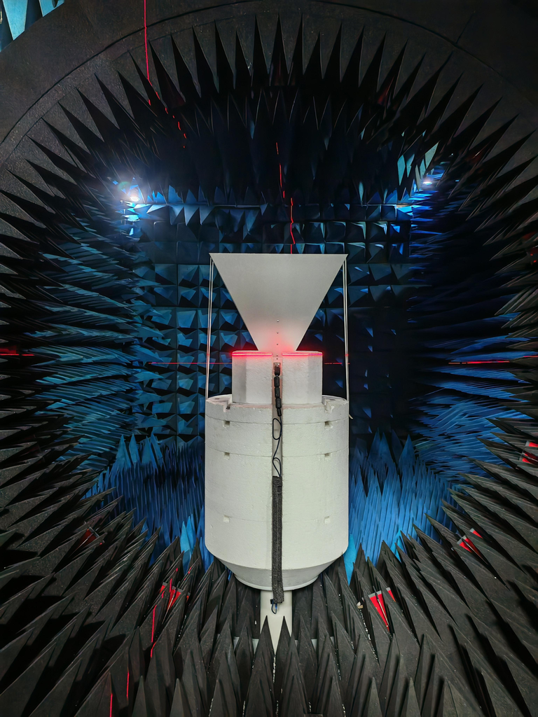
For radiated RF immunity testing, begin with the required field strength and test conditions. Then work backward through the antenna, RF transmission path, power amplifier, and signal source.
This order matters because the amplifier’s rated output does not tell you how much field strength the installed system can produce. Cable loss, antenna performance, chamber conditions, modulation, and RF power amplifier linearity all affect the result.
RF equipment selection and technical references
The table below separates the main selection checks from the documents needed to evaluate possible components. RF SKYPOWER resources are included where they provide relevant component information.
RF Chain Selection Path
Review the chain from source to field measurement; each stage needs both selection checks and supporting evidence.
Swipe horizontally to review the complete five-stage RF chain →
These documents help shortlist candidate components. An RF amplifier test report supports the measurements and conditions it records. The complete EMC test configuration still requires separate verification.
For example, the HZ20006000-100NA1 datasheet specifies saturated power under CW conditions. An immunity setup that requires modulated operation still needs evidence of usable amplifier power under those conditions.
The antenna requires a separate check. A horn may cover the intended frequency on paper but still be unsuitable because of its power-handling limit, gain at a particular frequency, or the field arrangement required by the test.
The available antenna PDFs also cover specific frequency bands. They should not be treated as evidence of performance outside those bands.
Verify power at the correct reference plane
Before accepting the RF chain, distinguish three measurements:
- Amplifier output: RF power measured at the defined amplifier output reference plane.
- Antenna input: RF power after the losses introduced by cables, couplers, switches, and other components.
- Field at the EUT: The electromagnetic field measured during the applicable field verification procedure.
These measurements cannot replace one another.
An RF amplifier output power test into a 50 Ω dummy load can verify power at the amplifier output reference plane. It cannot establish cable losses, antenna mismatch, or field strength at the EUT. Likewise, sufficient antenna input power does not guarantee the required field at the EUT.
The commissioning plan must account for the actual transmission path, field probe, test location, and relevant verification procedure.
Decide when the RF chain is ready
The component selection can proceed when the required frequency coverage, signal characteristics, operating power, RF interfaces, and thermal conditions are supported by appropriate evidence.
Hold the affected selection if any of the following remains unresolved:
- The amplifier power rating is available, but its usable performance under the required modulation is unknown.
- The signal source has the required frequency coverage, but the specified waveform or control behavior has not been demonstrated.
- Cable loss or the RF measurement reference plane is undefined.
- The antenna lacks relevant frequency-dependent data or sufficient power-handling evidence.
- The installed configuration has no agreed field verification plan.
For conducted RF immunity, replace the transmitting-antenna arrangement with the coupling or injection devices required by the applicable method. The equipment checks and verification procedure must follow that method.
The result should be a documented RF chain with defined operating conditions, identified measurement points, and a clear list of any remaining verification work.
4. What Should You Check Before Integrating Different Instruments?
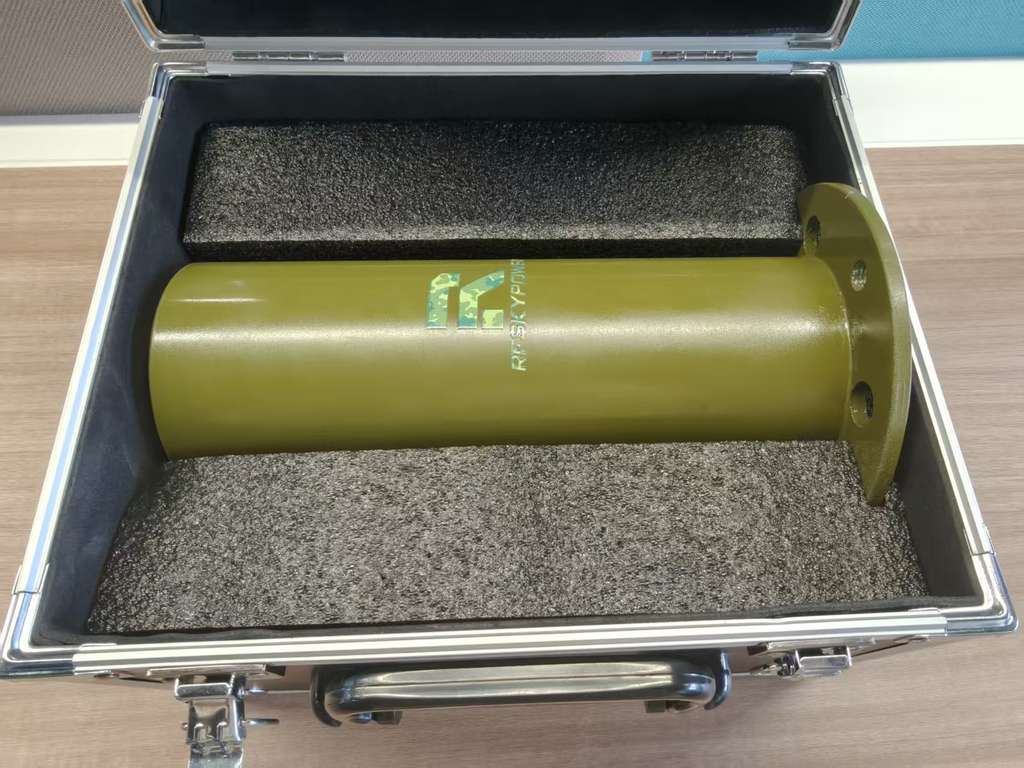
Before ordering, map the stimulus path, measurement reference planes, EUT monitoring, control interfaces, and safety functions. Assign an owner to each critical interface and agree on commissioning checks.
Check the signal and measurement paths
Start with the instruments and components that will exchange RF signals or measurement data.
Confirm their relevant frequency ranges, operating levels, impedances, connectors, power-handling limits, and protection requirements.
A measurement path also needs defined reference planes and correction data.
For example, cable-loss corrections established for one cable assembly may no longer apply after that assembly is replaced or rerouted.
The buyer should determine whether each performance statement applies to an individual instrument, a specified connected assembly, or the complete installed configuration.
A replacement component may meet its own specifications while changing the operating conditions or corrections used elsewhere in the system.
Verify software, facilities, and safety arrangements
EMC test software may control instruments, execute test sequences, capture measurements, and organize reports.
Check software compatibility with the actual instrument models, firmware revisions, drivers, communication interfaces, and software versions.
Include license coverage and supported functions in the purchasing review.
The integration plan must address abnormal operating conditions. A software command that stops a test sequence is not automatically equivalent to a hardware safety interlock.
Where hardware-level shutdown or protection is required, the system design must identify the responsible hardware and its intended behavior.
Depending on the test scope, the installation may require shielding, an anechoic chamber, suitable measurement grounding, fixtures, power distribution, cooling, ventilation, and defined cable routing.
Instrument location can affect cable losses, electromagnetic coupling, access, and safe operation.
The laboratory owner should identify which facilities already exist and which require modification. The supplier or system integrator must then state the installation conditions assumed in the proposal.
Plan how to monitor the EUT during immunity testing. Record its response under the specified operating conditions.
The monitoring function may depend on dedicated instruments, communication interfaces, software, or defined operator procedures.
Confirm the installed configuration
Commissioning should verify the agreed installed configuration rather than repeat only the instruments’ individual specifications.
The system verification scope may include interface operation, measurement corrections, software control, EUT monitoring, relevant safety functions, and method-specific checks.
A supplier that delivers only instruments may not provide these services.
The buyer needs a named party responsible for each agreed verification result.
If the installation conditions, software compatibility, measurement corrections, or safety responsibilities remain unresolved, the proposed system is not ready for final acceptance.
5. What Calibration and Verification Evidence Should Buyers Request?
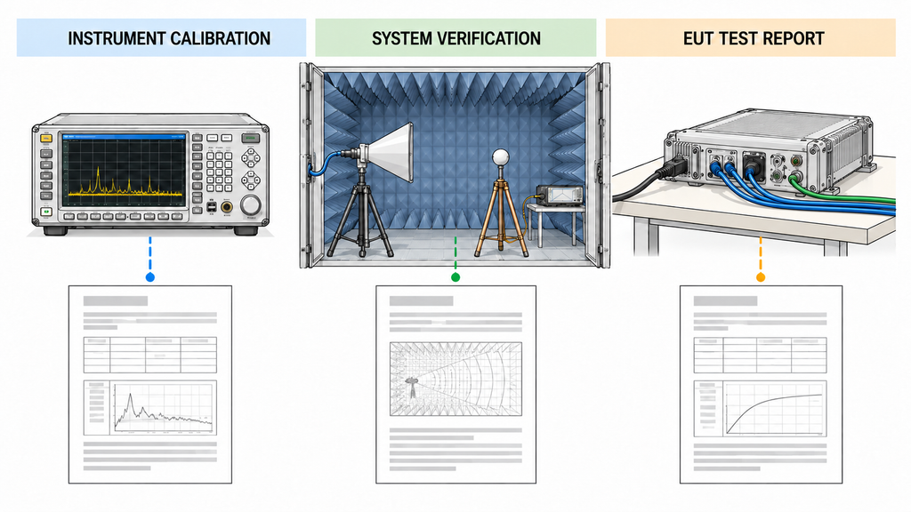
A calibration certificate for an individual instrument, an installed-system verification record, and an EUT test report prove different things.
Buyers need evidence that matches the equipment being supplied, the intended configuration, and the required test functions.
Instrument calibration and equipment records
For instruments requiring calibration or verification, request documentation linked to the actual equipment.
The records should identify the instrument, relevant configuration, calibration or verification status, covered measurement functions and ranges, and applicable uncertainty or traceability information.
A certificate may be genuine but insufficient if it does not cover the relevant operating range or measurement condition.
Representative test data may describe a different unit or configuration from the equipment being delivered.
The purchasing agreement should make clear which records must accompany the supplied instruments.
Installed-system verification
Individual instrument calibration does not establish the performance of every possible combination of instruments.
For a radiated RF immunity system, request the applicable field characterization records, amplifier-linearity checks, probe calibration information, and RF-path correction data.
Each record should identify the test method, relevant configuration, and conditions it supports.
For other immunity methods, the applicable generator, coupling arrangement, and verification requirements will differ.
System software and EUT monitoring may also require demonstration under the agreed installation and acceptance scope.
Link each verification record to the actual configuration. A verification result obtained with one cable, antenna, amplifier, or software arrangement may need reassessment after a relevant change.
The extent of any additional checking depends on what changed and how the change affects the applicable test method.
Keep equipment readiness separate from EUT results
Instrument calibration supports defined equipment functions under stated conditions.
Installed-system verification supports the readiness of a particular arrangement against an agreed verification scope.
An EUT test report records the behavior of a particular product under specified test conditions.
A system can be ready to perform a test without any particular EUT having passed that test.
Likewise, a supplier’s installation demonstration does not independently establish product certification or compliance.
The buyer should agree on the evidence required for equipment delivery, system commissioning, and any separately contracted EUT testing.
When documents cannot be connected to the delivered equipment or installed configuration, request the missing information before confirming the affected capability.
How Do You Compare EMC Equipment Suppliers and Prepare an RFQ?
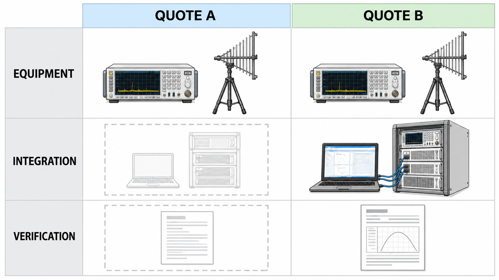
Two EMC equipment quotations can list similar models while assigning different integration and acceptance work to the buyer. An effective request for quotation (RFQ) makes those differences clear before comparing prices.
Define the evidence and responsibilities
The RFQ should specify the intended test methods, operating conditions, integration boundaries, required documents, and acceptance deliverables.
Request the following evidence with each quotation.
| Procurement requirement | Applicable scope or conditions | Supplier evidence requested | Responsible party | Hold condition |
|---|---|---|---|---|
| Test capability | Required EMC methods, product requirements, EUT types, intended laboratory use | Proposed capability coverage and identified exclusions | Buyer: defines scope; supplier: confirms coverage | Required test function missing or method applicability unclear |
| Instrument interfaces | Frequency, levels, impedance, connectors, measurement paths, existing equipment | Relevant specifications, interface details, connection and correction assumptions | Instrument supplier: device data; named integrator: installed interfaces | Critical interface or operating condition unverified |
| Laboratory and safety | Intended site, facilities, power, cooling, shielding, monitoring, interlocks | Site requirements, facility responsibilities, protection and safety provisions | Laboratory owner: facilities; named integrator: interface and safety verification | Facility capability or safety responsibility unresolved |
| Software and automation | Instrument models, firmware, drivers, licenses, control and reporting functions | Compatibility information, license scope, supported functions and limitations | Software supplier: supported functions; integrator: end-to-end operation | Required control or reporting function not demonstrated |
| Calibration and verification | Delivered equipment, intended ranges, installed configuration, agreed methods | Instrument certificates, verification procedures, planned system checks and records | Instrument supplier: certificates; designated verification owner: installed-system checks | Evidence does not cover the proposed configuration |
| Installation and support | Delivery scope, commissioning, training, documentation, future service | Scope of work, acceptance deliverables, support terms and exclusions | Named contractual lead: commissioning and handover | Installation or acceptance responsibility unclear |
For each acceptance deliverable, name one accountable party.
A component supplier may provide instrument-specific evidence, while the designated integrator or laboratory takes responsibility for the agreed installed-system verification.
Decide whether quotations are comparable
Classify each quotation before comparing prices:
Comparable: The proposals cover equivalent test capabilities, installation assumptions, documentation, and service scope. Their technical differences and commercial terms can be evaluated against the same requirements.
Partially comparable: Some deliverables are equivalent, but others differ. The buyer can compare the aligned portions while requesting clarification for the remaining scope.
Not comparable yet: Critical test functions, operating conditions, verification duties, or acceptance deliverables are missing or inconsistent.
Supplier A quotes an EMI receiver and antenna. Supplier B quotes similar instruments together with software integration and installed-site verification.
The instrument portions may be comparable, but the total proposals represent different delivery scopes.
The buyer should separate the equipment supply from the integration services and request clarification.
If Supplier A cannot identify who will verify the installed arrangement, the complete system proposals remain not comparable yet.
Confirm the delivery scope before selecting a supplier
State whether the supplier will provide individual instruments, integrated equipment, and software configuration. Define who will handle installation, commissioning, calibration services, operator training, and post-delivery support.
Include existing laboratory equipment in the review.
A new instrument may meet its published specifications but remain incompatible with the laboratory’s current control software or measurement arrangement.
Where the supplier is not responsible for integration, the buyer must assign that responsibility separately.
Move to final comparison only after aligning the required functions, operating conditions, evidence, and contractual responsibilities.
Missing information is a reason to request clarification, not proof that a product has failed.
For RF power amplifiers and other critical components, the RFQ should request evidence tied to the intended operating conditions rather than catalog ratings alone. Keep the component decision open until the supplier identifies the relevant performance basis, interfaces, and supporting test records.
Conclusion: Build an EMC Test Setup That Meets Your Requirements
Choose EMC test equipment by the methods your laboratory must support, then evaluate each instrument in its intended configuration. A suitable receiver, amplifier, or antenna does not make a complete system if interfaces, software, facilities, or verification records are missing.
Before sending an RFQ, list the required tests and EUT operating conditions. Identify equipment that can be reused, note missing functions, and assign responsibility for installation, safety, and verification. Ask suppliers to state exclusions and provide evidence for the exact proposed setup.
This selection process does not define project-specific test limits, guarantee the suitability of unverified equipment combinations, or prove that an EUT will pass its required tests.
If the setup needs an RF power amplifier, RF SKYPOWER can review amplifier-side requirements and available module options. Share the frequency range, modulation and signal conditions, input drive, operating power, antenna or coupling arrangement, load conditions, supply and cooling needs, control interfaces, and expected technical records.
The RF SKYPOWER engineering team can then discuss candidates and the information still needed for an application-specific decision.