










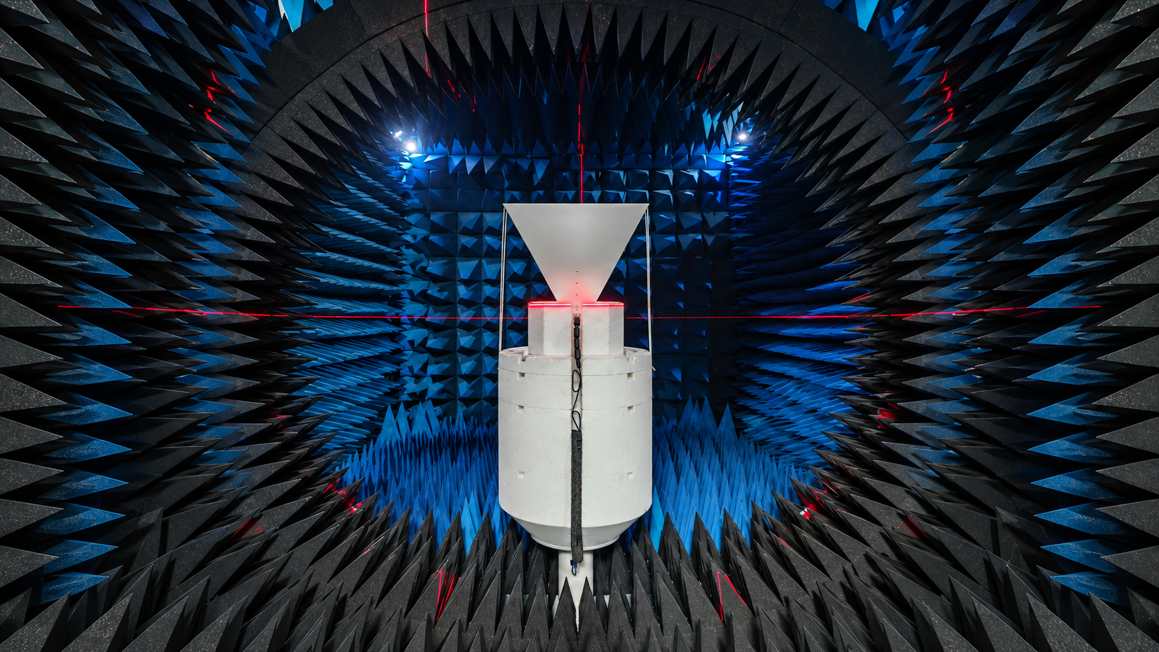
Choosing a broadband horn antenna for EMC immunity testing starts with the required electric field, test frequencies, and test geometry. The antenna must provide suitable performance across those conditions, while the connected RF amplifier and feeder system must supply enough usable power.
A wide operating range or high peak gain alone cannot establish suitability. An antenna may perform well near the center of its frequency range but lose considerable gain near the band edges. Its radiation pattern may also make it difficult to achieve the required field uniformity.
RF SKYPOWER offers several broadband horn antenna configurations with different frequency ranges, gain characteristics, and power ratings. The models below provide a starting point for comparing available hardware against your EMC immunity test requirements.
| Broadband Horn Antenna | Published Gain | Max. Input Power | Technical Information |
|---|---|---|---|
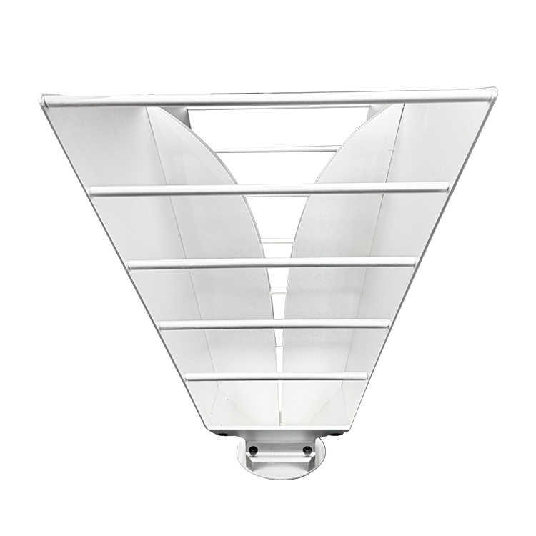 300–2700 MHz HornUltra-wideband horn | 16.19 dBi at 1300 MHz | 250 W | Datasheet & Test Report ↗ |
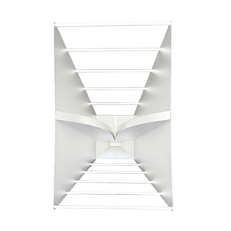 400–2700 MHz HornStandard directional horn | 5–10 dBi | 100 W | View Published Model ↗ |
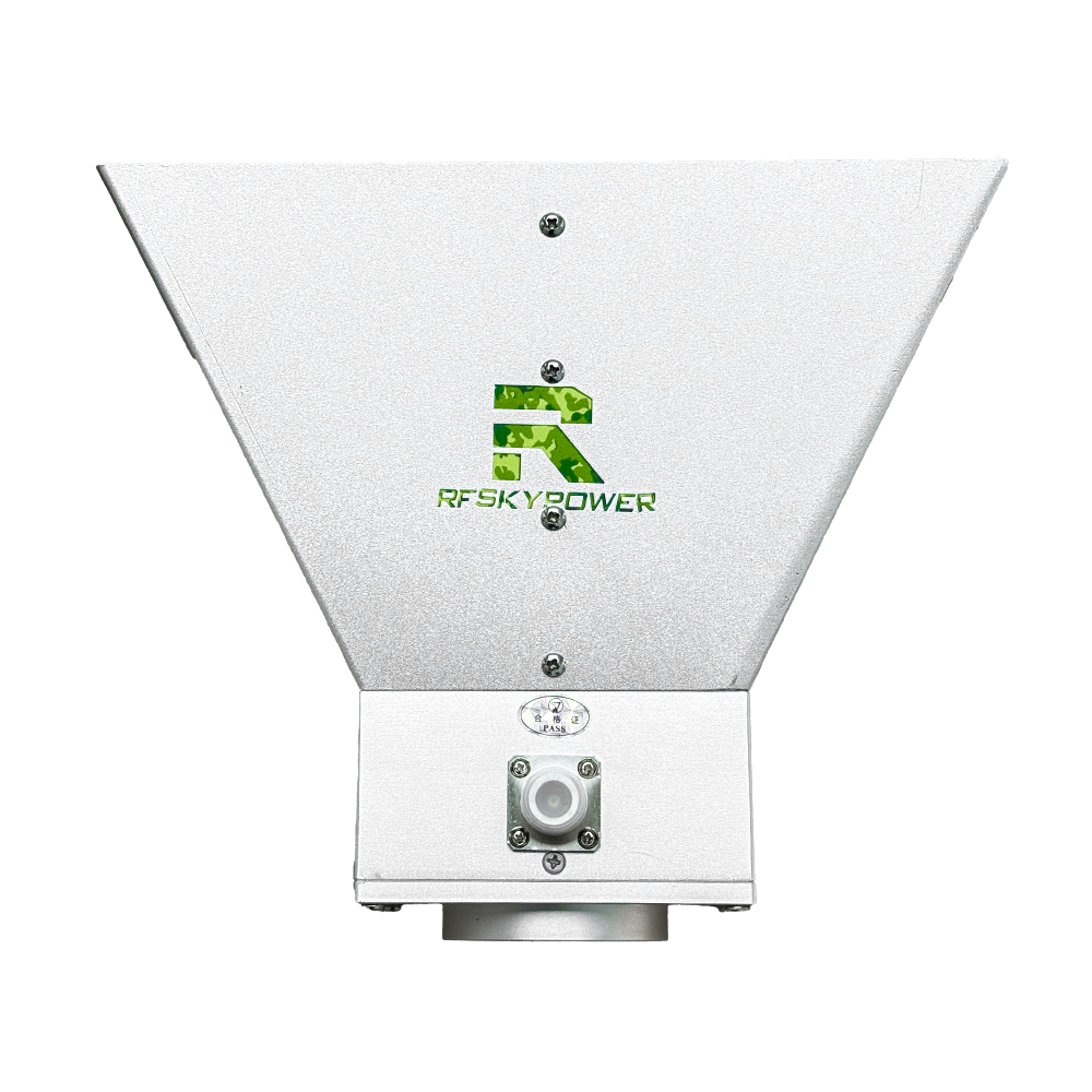 2000–6000 MHz HornHigh-gain long-range horn | 13.16–19.07 dBi | 100 W | Datasheet & Test Report ↗ |
 2–6 GHz Compact HornCompact tactical horn | 12–18 dBi | 100 W | View Published Model ↗ |
Swipe horizontally to compare all four antenna configurations →
Explore the RF SKYPOWER antenna product range for additional configurations. These specifications are intended for initial screening. Before selecting a model, engineers should confirm that a horn antenna is suitable for the required EMC test frequencies, field strength, and test geometry.
1. When Is a Broadband Horn Antenna the Right Choice for EMC Immunity Testing?
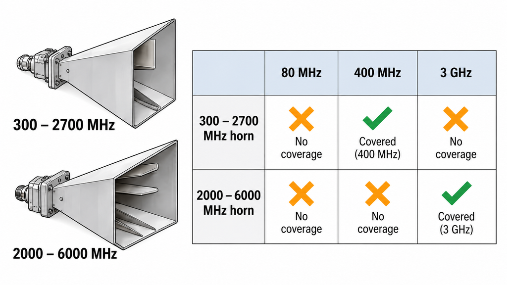
Start with the test frequencies and the area that must be exposed to the RF field.
IEC 61000-4-3:2020 establishes methods for evaluating equipment immunity to radiated radio-frequency electromagnetic fields. The applicable product standard and test plan determine the required frequencies, test levels, and performance criteria.
The test method does not require a horn antenna for every configuration. Double-ridged horn antennas can provide directional radiation over broad frequency ranges, making them useful for arrangements with defined antenna positions and test areas. Log-periodic or biconical antennas may be more appropriate for other frequency ranges or laboratory conditions.
Consider a hypothetical test plan covering 80 MHz, 400 MHz, and 3 GHz.
A horn rated for 300–2700 MHz nominally covers 400 MHz, while a 2000–6000 MHz horn covers 3 GHz. Neither includes 80 MHz. Using both horns would still leave part of the test range uncovered, requiring another suitable antenna or a different configuration.
A missing frequency and missing performance data are different problems. A horn rated for frequencies above 300 MHz cannot serve as the only antenna for an 80 MHz requirement. If a required frequency falls within its rated range but relevant gain measurements are unavailable, the model may remain under consideration while the supplier provides further data.
Frequency coverage is the first filter. The antenna’s directional characteristics must also suit the test distance and required uniform field area.
A high-gain horn may concentrate more energy toward a smaller region. A wider radiation pattern may cover more of the test area but increase the amplifier power needed to maintain the target field.
Engineers should confirm the antenna type, frequency coverage, and intended geometry before selecting a model. If the test standard or installation conditions remain undefined, a meaningful comparison is premature.
2. Which Test Frequencies and Field Strengths Should Drive Antenna Selection?
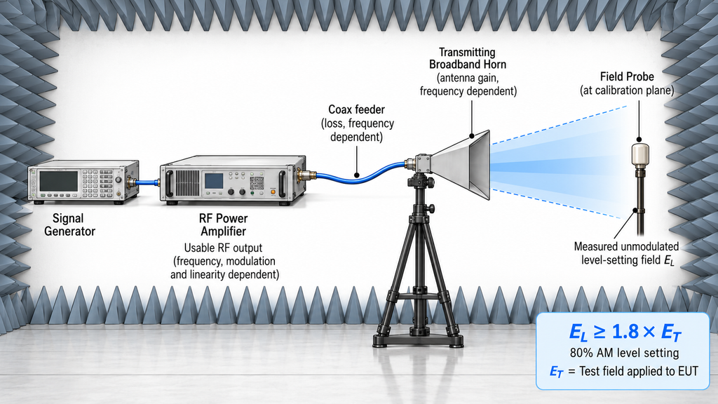
The most demanding test frequency often determines the required antenna and amplifier combination.
Engineers should first establish the frequency range, target electric-field strength, modulation, test distance, polarization, equipment under test (EUT) dimensions, and required uniform field area.
A higher target field may require more RF power. Increasing the test distance can also raise the power requirement, while a larger test area may favor different radiation characteristics.
However, the frequency with the lowest antenna gain is not always the most demanding point for the complete system.
An antenna may lose gain near its lower band edge. At another frequency, the amplifier may deliver less usable output, the feeder may introduce greater loss, or the chamber may produce a less favorable field distribution.
The limiting frequency is the required test point where the configured RF chain has the least usable margin for producing the specified field.
During procurement, engineers can identify likely limiting frequencies using gain curves, amplifier output data, and estimated feeder losses.
The field-level-setting requirements also matter.
For the IEC 61000-4-3:2020 level-setting procedure using 80% amplitude modulation (AM), the unmodulated level-setting field is established at least 1.8 times the field strength to be applied to the EUT.
This requirement affects the field level the system must produce. It does not establish a universal multiplier for amplifier power, which depends on the antenna, chamber, and RF chain.
The applicable amplifier linearity checks must also be considered. Selecting an amplifier solely from the nominal test field strength can underestimate the usable output required.
Engineers should therefore review band edges, gain minima, changes in amplifier performance, and frequencies identified as critical by the test plan.
These are preliminary findings. Field calibration and verification of the actual operating conditions establish whether the configured system can achieve the required field.
A frequency that appears demanding from datasheet calculations may prove less restrictive in the installed chamber. Another may become the limiting point because of measured field distribution or amplifier behavior.
Comparisons also need consistent conditions. Field-strength results obtained at different distances, polarizations, or chamber arrangements are not automatically equivalent.
The buyer should finish this stage with defined test conditions and a set of potentially limiting frequencies. Without those inputs, any power estimate remains provisional.
3. How Do Gain and VSWR Curves Affect the Required RF Amplifier Power?
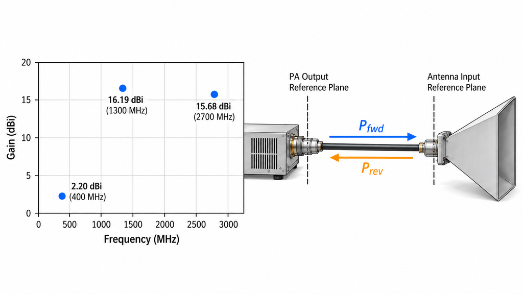
Antenna gain determines directional radiation performance. Voltage standing wave ratio (VSWR) describes impedance matching at the antenna input. Both influence RF system performance, but they must be evaluated separately.
RF SKYPOWER’s published 300–2700 MHz horn antenna specification and test report includes frequency-specific gain measurements.
The reported gain is 2.20 dBi at 400 MHz, 16.19 dBi at 1300 MHz, and 15.68 dBi at 2700 MHz. These are published measurement results, not guaranteed values for every delivered antenna.
The difference between 400 MHz and 1300 MHz is approximately 14 dB, corresponding to a linear gain ratio of about 25:1.
That variation matters when assessing amplifier power. It does not mean an EMC test will require exactly 25 times more amplifier power at 400 MHz.
Such a power comparison requires consistent gain definitions, measurement directions, distances, and mismatch treatment. A simplified far-field estimate can indicate the effect of lower gain, but it cannot predict the actual power requirement inside a particular EMC chamber.
Chamber behavior, the antenna radiation pattern, usable amplifier output, and the required field area all affect the result.
The published report also does not establish measured gain at 300 MHz. Although the antenna is rated from 300 MHz, buyers requiring performance at that frequency should request supporting measurements.
VSWR presents a different concern.
A higher VSWR indicates greater mismatch and potentially more reflected power. Depending on its protection settings, the RF amplifier may reduce output, issue an alarm, or enter a protective state.
That behavior can affect the available field, but VSWR alone cannot establish field strength at the EUT.
Power measurements must be assigned to the correct reference plane. Amplifier output power is measured at the PA output connector. Forward power at the antenna input is the incident power arriving after feeder losses. Accepted antenna power excludes the portion reflected at the antenna connector.
The antenna gain definition matters here. Conventional gain and realized gain treat mismatch differently. Applying a separate mismatch correction without checking the reported gain definition may count the same loss twice.
An amplifier characterized with a matched dummy load may behave differently when connected to a real antenna load, particularly where reflected power affects its operation.
For preliminary selection, combine frequency-specific gain and VSWR data with feeder losses and the amplifier’s usable output under the intended conditions.
If the necessary data or reference planes are unclear, request them before finalizing the power budget. Peak antenna gain and nominal amplifier output are insufficient for that decision.
4. Can the Antenna Beamwidth and Polarization Meet Field Uniformity Requirements?
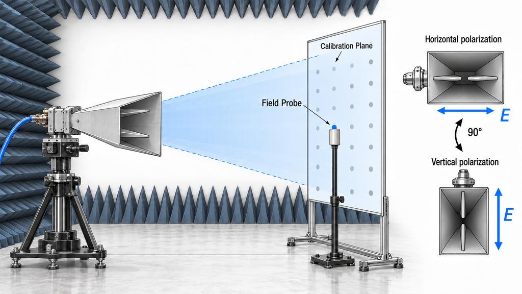
A strong electric field along the antenna’s main beam does not guarantee adequate field uniformity across the required test area.
Horn antenna radiation patterns vary with frequency and may differ between the principal E-plane and H-plane cuts.
A narrower beam can provide higher directional gain, although it may concentrate the field within a smaller region. A wider pattern may cover more of the test area while requiring additional amplifier power to maintain the specified field strength.
The appropriate choice depends on the test geometry and permitted illumination method.
Under IEC 61000-4-3:2020, full illumination is the preferred approach. Where the applicable procedure permits partial illumination, an antenna that cannot cover the entire EUT in one position may still be suitable. The required areas must be covered using the prescribed and verified antenna or EUT positions.
The antenna’s half-power beamwidth provides useful screening information. It describes the angular separation between the points where radiation power falls by 3 dB relative to the relevant maximum.
It does not establish the electric-field distribution throughout an EMC chamber.
The required uniform field area must be verified using an appropriately calibrated electric-field probe and the applicable field-calibration procedure. Measurements at the prescribed positions determine whether the specified criteria are met.
Before purchasing, engineers should examine radiation patterns at the frequencies most relevant to the test. If plots are provided only at selected frequencies, their behavior cannot automatically be extended across the entire operating range.
Polarization also affects the installation.
For a linearly polarized horn, horizontal polarization can often be obtained by rotating the antenna by 90 degrees. The mounting system must support the required orientations while maintaining the intended beam direction and calibration conditions.
Mechanical clearance, cable routing, and the available mounting arrangement may limit how the antenna can be positioned.
A datasheet identifying vertical polarization does not, by itself, answer whether the complete installation supports both required orientations.
The purchasing decision should account for the available radiation patterns, mounting options, and intended illumination method. Final field uniformity remains a property of the configured test system, established through the applicable calibration procedure.
5. Does the Antenna Power Rating Match the Actual Immunity Test Conditions?
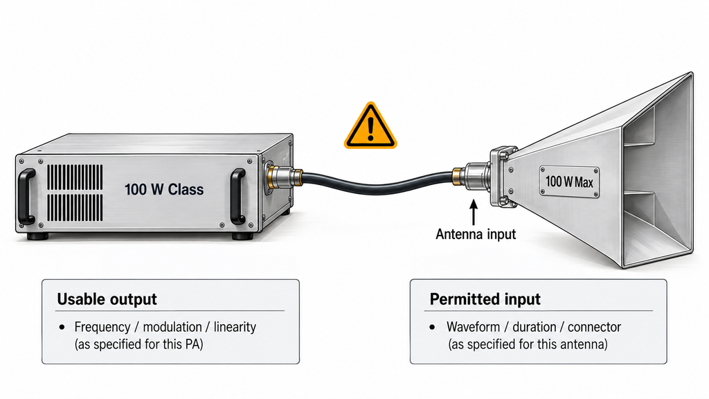
An antenna’s maximum input-power rating must be evaluated under the conditions for which it applies.
Frequency, waveform, operating duration, temperature, and connector capability can all affect the permissible input power.
Consider a 2000–6000 MHz horn antenna rated for a maximum input power of 100 W.
A 100 W-class broadband RF amplifier operating over the same frequency range may appear to be a suitable match. Yet the two ratings describe different equipment limits, and their numerical agreement does not establish system compatibility.
The amplifier’s published output may represent saturated power under specified conditions.
For EMC immunity testing, engineers should verify RF power amplifier linearity at the specified modulation and operating point before determining how much output is usable.
Where the test procedure specifies harmonic-content limits, engineers should check RF amplifier harmonic distortion at the intended operating point, particularly near compression.
The antenna rating requires a separate check. Continuous average power, peak power, and permitted operating duration are not interchangeable.
A modulated waveform must be evaluated against the appropriate rating definition. Its peak power cannot be compared directly with an antenna limit whose conditions are unspecified.
Frequency-dependent ratings, thermal restrictions, and connector limits should be included in the assessment.
The expected antenna-input power must remain within the applicable limits. The calculation should use consistent reference planes and the feeder-loss and mismatch definitions established during the power-budget review.
Amplifier behavior under load matters as well. If mismatch or temperature causes output reduction or protection, the system may be unable to maintain the required field even when its nominal power rating appears sufficient.
When comparing RF power amplifier module specifications, use the output available at the required frequency, waveform, linearity, and operating point rather than the headline power class.
A combination can receive technical approval only when its power definitions and operating limits are compatible with the intended test. If those limits are unclear, request the relevant conditions before proceeding.
6. What Calibration Data Should Be Checked Before Approving a Horn Antenna?
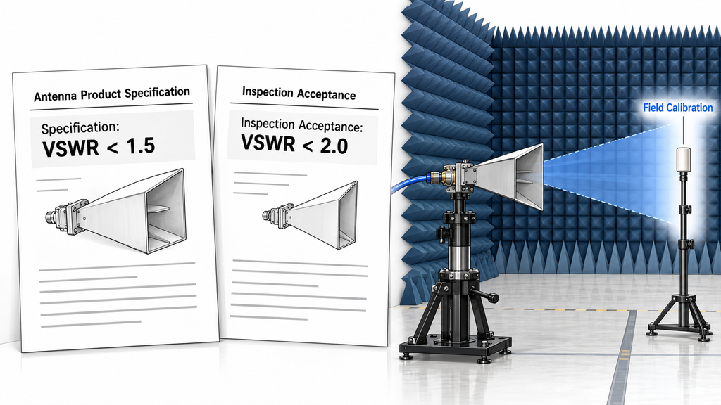
Antenna procurement and EMC system calibration require different evidence.
Before purchasing, engineers can evaluate the antenna’s published specifications, measured performance, and available calibration records. After installation, the configured test system must undergo the field verification required by the applicable procedure.
The latter may not be available before the antenna is purchased. Procurement should therefore establish what evidence is needed immediately and what must be verified after the system is configured.
A product datasheet typically lists frequency coverage, gain, VSWR, power handling, and radiation patterns.
A measurement report provides more specific evidence when it identifies the tested hardware, method, frequency points, and measurement conditions. The buyer must establish whether the results apply to a representative sample, a defined production unit, or another specified scope.
A sample report should not be treated as a measurement guarantee for every delivered antenna.
This matters when different limits appear in the same documentation.
For RF SKYPOWER’s published 300–2700 MHz horn antenna, the specification states VSWR below 1.5, while the inspection conclusion reports acceptance against a limit below 2.0.
The published summary does not establish whether every delivered unit meets the tighter limit throughout the specified frequency range.
Buyers requiring VSWR below 1.5 should request corresponding frequency-dependent measurements or acceptance records for the relevant units.
The same principle applies to gain and radiation patterns. Results at selected frequencies do not establish performance at every unmeasured point.
Antenna calibration records also need to be interpreted according to their purpose. They may establish measured characteristics for a specified antenna and method. Where the project requires unit-level traceability, the records should identify the corresponding hardware.
These records do not establish field uniformity for an entire EMC test arrangement.
The configured system must be evaluated using the applicable field-calibration procedure. Existing calibration records remain relevant only while their documented configuration and conditions apply. Replacing or repositioning the antenna, or changing another significant part of the RF chain, may require reassessment.
Procurement approval therefore depends on evidence that the candidate meets the applicable purchase requirements and can proceed to the necessary system-level verification.
Test-system approval requires the evidence applicable to the completed configuration, including field calibration and any other specified checks.
Missing product measurements may prevent procurement approval when they concern mandatory requirements. Field-calibration results that can only be obtained after installation should instead be defined as subsequent verification obligations.
Keeping these stages separate allows buyers to make an informed equipment decision without treating product documentation as proof of complete EMC system performance.
How Should Engineers Shortlist a Broadband Horn Antenna Before RFQ?
Build the shortlist around the actual test requirements and the evidence available for each candidate.
Three comparison outcomes are useful:
Comparable: The essential specifications and supporting measurements are available under sufficiently consistent conditions.
Partially comparable: Some parameters can be compared, but missing information prevents a complete decision.
Not comparable yet: Critical requirements, measurement definitions, or supporting evidence are missing or incompatible.
These states describe whether a valid comparison is possible. They do not override a known technical limitation.
For example, an antenna rated from 300 MHz cannot independently cover an 80 MHz test requirement. That is a frequency mismatch, whereas missing gain data at an in-band frequency is an evidence gap.
Broadband Horn Antenna Selection Matrix
| Check | Buyer action | When to Hold or Exclude |
|---|---|---|
| Frequency coverage | Match every required test frequency against the rated range and available performance data. | Exclude as a standalone solution if a required frequency is outside the rated range, or specify an additional antenna. Hold if essential in-band evidence is missing. |
| Gain | Check critical-frequency gain and distinguish measured, typical, peak, and guaranteed specifications. | Hold when only peak gain is available but frequency-specific performance must be established. |
| VSWR | Review matching data across the required frequencies and check amplifier load limits. | Hold if necessary mismatch data or acceptance limits are unclear. |
| Power handling | Compare expected antenna-input power with the rating under the required frequency, waveform, and duration. | Hold when rating conditions are unknown. Reject an operating condition that exceeds a verified limit. |
| Beamwidth and polarization | Check radiation patterns, test geometry, required orientations, and mounting arrangements. | Hold if essential pattern or polarization information is unavailable. |
| Calibration evidence | Verify procurement-stage measurements and records, then define the required system field-calibration obligations. | Hold if mandatory product evidence is missing or the system-verification requirements cannot be defined. |
A candidate with missing information can remain under consideration while the supplier provides the necessary evidence. A confirmed mismatch with a mandatory requirement calls for a different candidate or a revised configuration.
Where suppliers report parameters under incompatible conditions, request comparable measurements before ranking their products.
Technical Data to Include in the RFQ
A request for quotation (RFQ) should define the application clearly enough for suppliers to evaluate the same requirements.
Include:
- Applicable standard and test plan: Standard edition, product-specific requirements, test levels, and performance criteria.
- Frequency requirements: Complete test range and frequencies requiring closer evaluation.
- Field conditions: Target electric-field strength, modulation, waveform, required field-calibration conditions, and operating duration.
- Test geometry: Test distance, chamber arrangement, EUT dimensions, and required uniform field area.
- Polarization: Required orientations and mounting constraints.
- Existing RF amplifier: Usable output under the intended conditions, frequency coverage, linearity requirements, and load limitations.
- Feeder and interface: Cable losses, connector types, adapters, and antenna-input reference plane.
- Antenna performance evidence: Frequency-dependent gain, VSWR, radiation patterns, applicable power ratings, and measurement conditions.
- Verification requirements: Product measurements, calibration records, equipment identification, unit traceability where required, and subsequent system field-calibration obligations.
Separate mandatory acceptance requirements from information requested for further evaluation.
If a supplier cannot substantiate a mandatory parameter, keep the item unresolved until suitable evidence is available. If a candidate exceeds a verified limit or fails a required frequency condition, exclude it for that configuration or revise the system design.
This produces a shortlist based on comparable engineering evidence rather than unmatched datasheet figures.
Conclusion
Peak gain alone cannot establish whether a broadband horn antenna is suitable for EMC immunity testing. Its frequency-dependent performance and operating limits must match the actual test requirements. Confirm that the antenna, amplifier, feeder, and test geometry can support the specified field conditions.
The selection process can identify suitable candidates and distinguish missing evidence from confirmed limitations. It cannot establish final EMC system performance without the required configuration-specific verification and field calibration.
Before purchasing, identify the potentially limiting frequencies, compare measurements under consistent conditions, and document any remaining product or system verification requirements.
For a project-specific assessment, contact RF SKYPOWER’s engineering team with the applicable test standard, frequency range, target field strength, modulation, field-calibration requirements, test distance, uniform field area, polarization, existing amplifier and feeder details, and required technical evidence. These inputs allow the available horn antenna and RF amplifier hardware to be evaluated against your test requirements.