










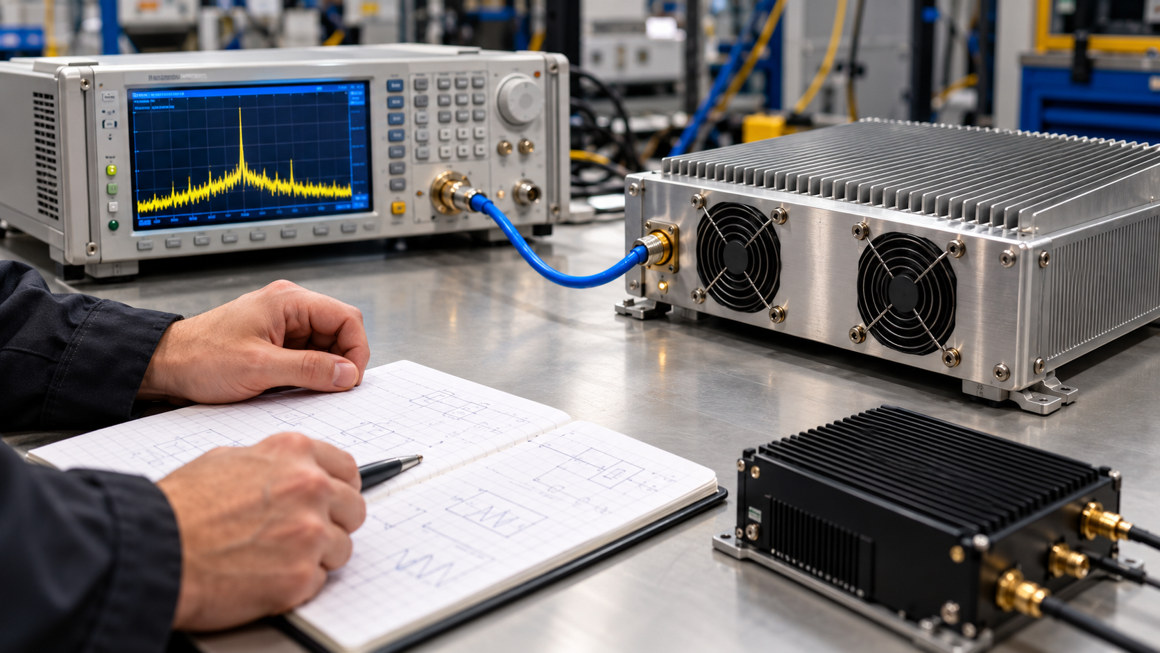
An RF signal generator should match the PA task it must support. A conventional analog source may be enough for continuous-wave (CW) checks and frequency sweeps. A vector signal generator (VSG) often suits digital modulation. A transmitting software-defined radio (SDR) may suit custom I/Q or embedded work. Its RF output must meet the project needs.
A VSG is one type of RF signal generator. SDR describes a programmable radio architecture, not a guaranteed level of RF performance. Neither the equipment name nor its output setting proves what reaches the power amplifier (PA). Start with the job the source must perform.
1. What Does the PA Drive Source Need to Accomplish?
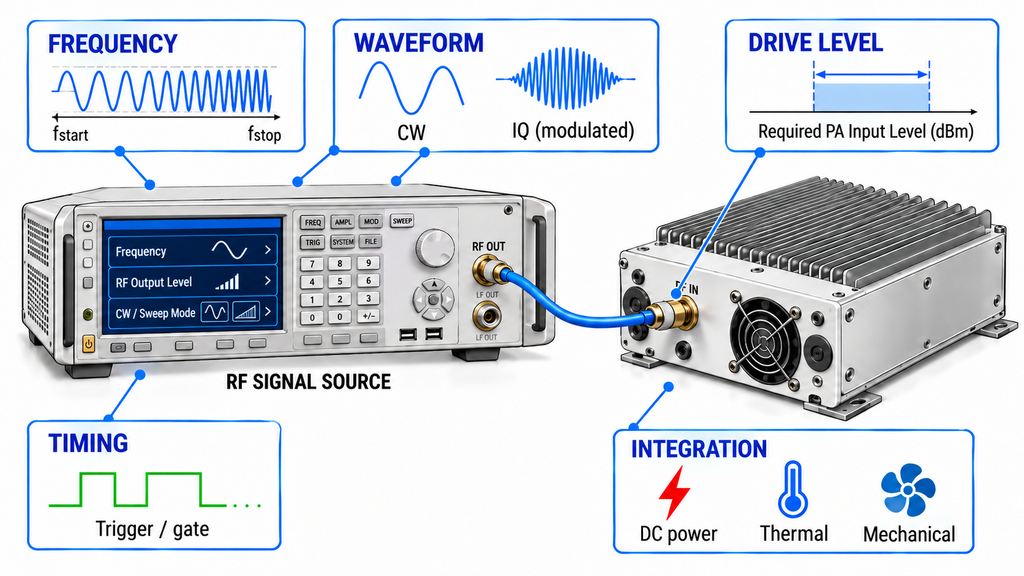
A CW gain check needs a controlled carrier at the required frequency and level. A swept test also needs suitable frequency coverage, settling behavior, and level consistency across the test points.
A digital-modulation PA test needs a known waveform and a clean source. Check its bandwidth and distortion against the test goal. Production retesting adds repeatable settings, calibration records, and version control. Custom waveform work requires supported I/Q data and reliable RF playback.
Multichannel work raises a separate question. Must signals start together, share a frequency reference, or hold a defined phase relationship? Those are different requirements.
An embedded source must also fit the supply, thermal, mechanical, and maintenance limits of the system. These limits can rule out a candidate even when its waveform capability looks suitable.
Define the target frequencies, waveform and bandwidth, intended PA measurement, drive conditions, and timing needs before comparing models. State which results require calibrated evidence. If the task or waveform remains undefined, do not shortlist devices based only on frequency range or rated output.
2. Is a VSG Different from an RF Signal Generator?
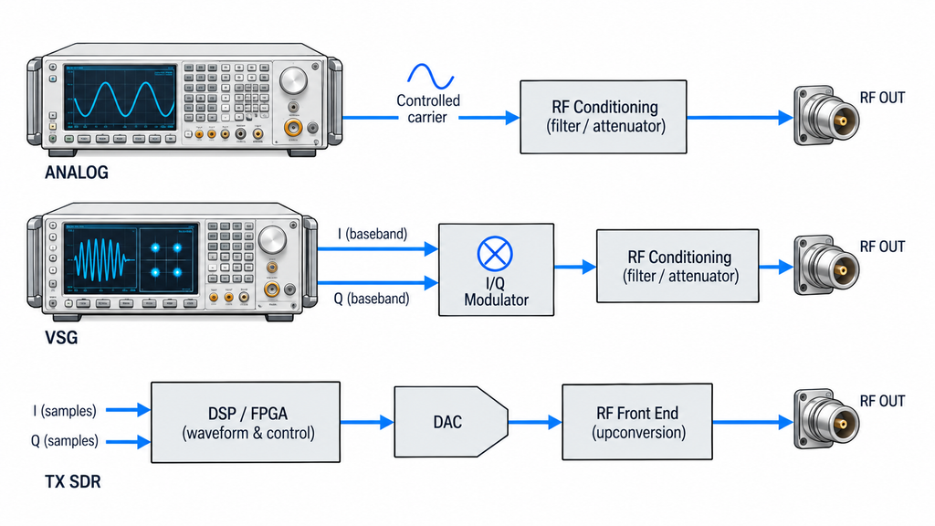
An analog RF signal generator provides a controlled carrier. Some models also support sweeps and basic modulation.
A VSG adds complex modulation through in-phase and quadrature (I/Q) signal components. It can create many digitally modulated waveforms. Supported formats, bandwidth, waveform memory, and options still vary by instrument.
A transmitting SDR creates RF through a programmable digital chain and RF hardware. It may play standard or custom I/Q signals. Output accuracy, noise, and linearity still depend on the model and setup.
Together, I and Q form a complex baseband signal that controls RF amplitude and phase. The I/Q-to-RF conversion path explains how digital samples become an RF waveform. Playback success alone does not confirm waveform quality at the output.
Some VSGs offer broad software control, while some SDRs have calibrated outputs. No class is always cleaner or more accurate. Compare the installed options, physical RF ports, calibration conditions, and model-specific test evidence. If a supplier supplies only a category name, request the actual configuration.
3. Which Source Fits CW, Modulated, and Custom-IQ PA Work?
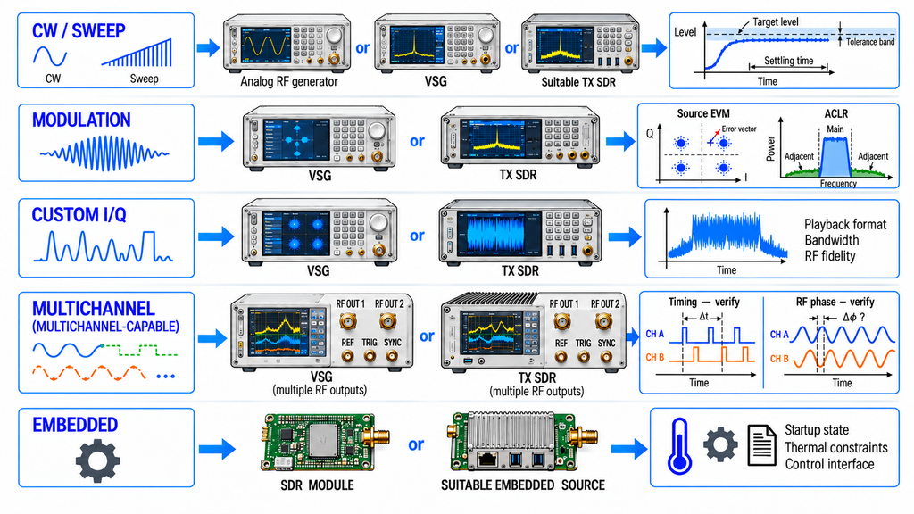
Use the PA task to qualify source classes. Then compare individual models under matching conditions.
| PA task | Candidate source class | Capability to prove | Evidence required | Stop condition |
|---|---|---|---|---|
| Basic CW or frequency-sweep checks | Analog RF generator; suitable VSG or SDR | Carrier coverage, stable level, and required sweep behavior | Frequency, level, flatness, and settling data at test points | Frequency, level accuracy, or settling unverified |
| Digitally modulated PA testing | VSG or suitable transmitting SDR | Required modulation, bandwidth, and source waveform quality | Waveform settings and source EVM/ACLR at required level and bandwidth | No relevant source EVM/ACLR baseline for the planned test |
| Custom I/Q waveform generation | I/Q-capable VSG or SDR | Sample format, playback, RF bandwidth, and output quality | File/interface data and RF playback results for the exact version | Format, bandwidth, or output waveform remains unverified |
| Synchronized multichannel work | Suitable multichannel VSG or SDR | Physical RF-port count, triggers, timing, and phase behavior where needed | Port map, timing specifications, and relevant synchronization measurements | Required port count, timing accuracy, or phase behavior lacks evidence |
| Embedded waveform generation | SDR module or suitable embedded source | RF output, control, startup state, supply, thermal, and mechanical fit | Model/revision documents and setup checks | Startup RF state, control path, or integration limits remain unclear |
The matrix filters candidates; it does not rank brands. An I/Q-capable VSG and an SDR may both qualify for the same task.
For performance comparisons, align frequency, waveform, output-power definition, reference plane, test method, and source revision. Otherwise, compare only the evidence that uses equivalent conditions.
The source waveform and the PA result also need separate interpretation. CW and modulated PA testing have different evidence requirements after the stimulus has been selected.
4. Can the Source Deliver the Required Level at the PA Input?
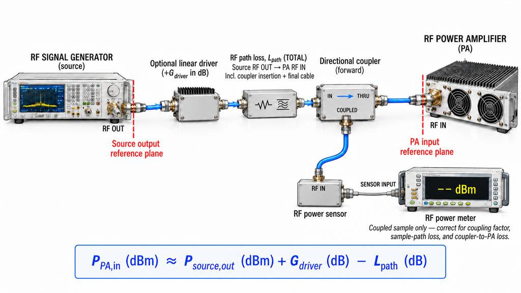
The generator’s RF output connector and the PA input are different reference planes. Between them may be cables, switches, couplers, attenuators, filters, or a driver stage.
For a defined, approximately linear path, use this planning estimate:
Estimated PA input (dBm) ≈ source output (dBm) + driver gain (dB) − path loss (dB).
Source output refers to power at the source’s defined RF reference plane. A front-panel setting may differ from the output delivered there.
Check the source’s stated level accuracy and flatness at each key frequency and power level. Read the test and calibration conditions behind those figures. Then check the full RF path to the PA. A calibrated source does not calibrate its cables, switches, or driver.
The estimate cannot replace an input measurement or a calibrated path calculation. Loss changes with frequency. Mismatch, gain compression, drift, and uncertainty can also alter delivered power.
For a modulated waveform, specify both average and peak-power requirements where relevant. The peaks may exceed the average level. Check the PA’s useful drive range and maximum safe input, as well as the source’s usable output range. Too little drive may miss the target output. Too much may cause compression, distortion, heating, or protection events.
If the PA input window, power definition, or path conditions remain unknown, direct compatibility is not established. Measuring actual PA input power requires a defined reference plane. A separate SDR drive-margin check addresses the usable source-to-PA window.
5. When Do Phase Noise, Spurs, and Triggering Change the Choice?
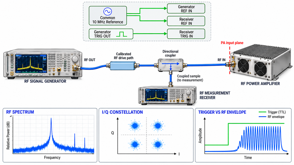
Two sources can produce the same nominal waveform yet lead to different PA measurements. Check the stimulus quality at the PA input reference plane, not only at the generator connector. A driver stage or other RF-path element can alter that quality. The measurement receiver can also affect the reported result.
Source purity and modulation quality
Frequency accuracy describes how closely the carrier matches its assigned frequency. Phase noise describes fluctuations around that carrier. Compare phase-noise data at the offset frequencies that matter to the test, under the stated source conditions.
For spurious emissions and harmonics, request the unwanted frequencies, levels, and measurement settings. Include the relevant resolution bandwidth. Source-related components may appear at the PA output and distort the interpretation.
For digital modulation, compare the stimulus EVM and adjacent-channel baseline with the measurement objective. Use the intended waveform, output level, and bandwidth. If source or receiver imperfections could dominate the result, the available data cannot isolate the PA’s contribution.
Also check usable I/Q bandwidth and waveform peaks. Sample rate is not the same as occupied RF bandwidth. Peak-to-average power ratio may change the required output headroom.
No single noise, spur, or EVM threshold applies to every PA test. Ask for source-baseline evidence under comparable conditions before ranking performance.
Triggering and synchronization
Pulsed and dynamic tests may need trigger inputs, waveform markers, or repeatable output timing. Confirm the timing behavior of the actual hardware and software configuration.
A shared reference clock supports a common frequency basis. It does not by itself prove phase coherence between RF outputs. If the test needs a stable phase relationship, request evidence for that requirement.
Match the trigger method, clock arrangement, output ports, and test conditions across candidates. Without the decisive timing evidence, hold the synchronization comparison.
6. What Changes Between a Bench Instrument and an Embedded Source?
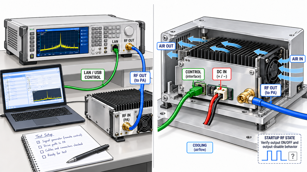
Bench instruments can provide reusable test setups and documented calibration procedures. Their actual accuracy, remote-control options, and calibration status remain model-specific.
For an automated bench, verify the supported commands, trigger I/O, and interfaces. Some instruments use SCPI through LAN, USB, or GPIB. Do not assume every device supports the same commands or functions.
An embedded source must fit the supply, heat, and space limits. It also needs suitable RF ports, controls, firmware support, and calibration access.
Startup behavior deserves explicit review. Some devices can restore a saved transmit configuration when power returns. Check the initial RF state, output-disable behavior, and firmware revision before connecting the source to a PA.
RF SKYPOWER offers SDR Signal Source Modules for embedded-source evaluation. Public model documentation describes RS422 control for certain configurations. This supports a product-discovery route, not a claim of bench-VSG measurement accuracy.
A dual-PHY description also does not prove the number of physical RF output connectors. Confirm the exact RF ports, control interface, and operating conditions in the applicable revision.
A candidate may satisfy RF waveform requirements and still fail the integration needs of the project. If the required ports, startup state, or system limits remain undocumented, pause the integration decision.
7. What Evidence Should You Request Before Choosing a PA Driver Source?
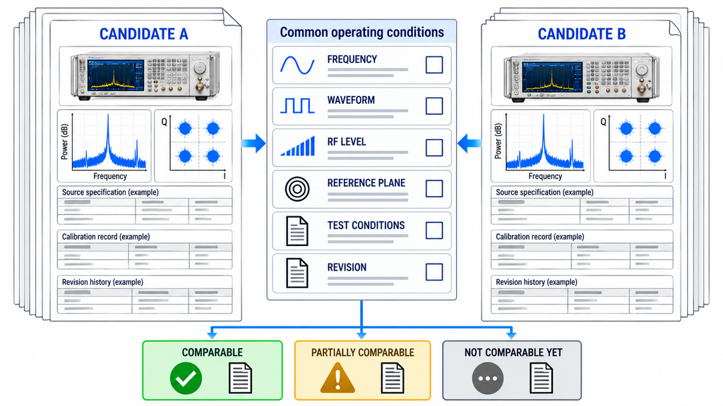
Send each supplier the same operating conditions. Record what each source can prove and what remains missing.
- Application and waveform: Target PA, operating frequencies, modulation or custom I/Q, occupied bandwidth, real-time bandwidth, and intended measurement.
- Levels and RF interfaces: Physical RF ports, source output range, average and peak-power definitions, path gain and loss, actual PA input plane, and required input window.
- Signal quality and timing: Phase-noise offsets, spur and harmonic test settings, EVM/ACLR baseline, triggers, reference clocks, and phase requirements.
- Integration: Control/API support, hardware and firmware versions, startup RF state, supply, mechanical fit, cooling, and environment.
- Evidence scope: Datasheet revision, installed options, test setup, calibration plane and date, measured unit or sample scope, and unresolved fields.
A typical specification, a calibrated measurement, and a result from one unit do not prove the same thing. Check the conditions and scope of every claim.
Classify each candidate based on the evidence:
- Comparable: The decision-critical conditions match, and the evidence supports the intended comparison.
- Partially comparable: Some capabilities can be compared, but other results use different conditions or lack data.
- Not comparable yet: Missing evidence could change the selection, so a performance ranking would be premature.
For example, Supplier A may document CW output but give no EVM baseline for your waveform. If Supplier B provides matching CW data, you can compare their CW capability. Hold the modulation comparison until both supply EVM data for the same waveform, power, and bandwidth. Missing data does not prove that a product fails.
If the PA model is still open, the RF Power Amplifier Modules range can help define a candidate family and input requirements. A product listing does not prove that any source and PA pair has passed integration testing.
Once the source class and candidates are qualified, verify the source output and the drive delivered at the PA input under controlled conditions. That is the next engineering stage, not a result already established by this comparison.
Conclusion
An analog RF generator may be enough for a defined CW or sweep task. A capable VSG often fits controlled digital modulation. A transmitting SDR may suit custom I/Q and embedded work. Each remains a candidate only when its waveform, output level, source quality, timing, and interfaces meet the project conditions.
This framework can qualify source classes and identify missing supplier evidence. It cannot set universal acceptance limits, certify a particular model, or replace PA-port verification. A VSG is still an RF signal generator, and a source setting is not actual PA input power.
Before requesting a quote, freeze the operating conditions and compare evidence on the same basis. Record missing items, then plan controlled source-output and PA-input checks.
For an embedded SDR route, review RF SKYPOWER’s SDR Signal Source Modules against the required interfaces and waveform conditions.
For project-specific evaluation, request an engineering review. Provide the frequency points, modulation and bandwidth, PA model or input range, source average and peak levels, and path gain or loss. Include physical RF-port count, control and synchronization needs, supply and environment, and the calibration or test evidence required.
An inquiry starts a technical review; it does not certify the source–PA pair.