










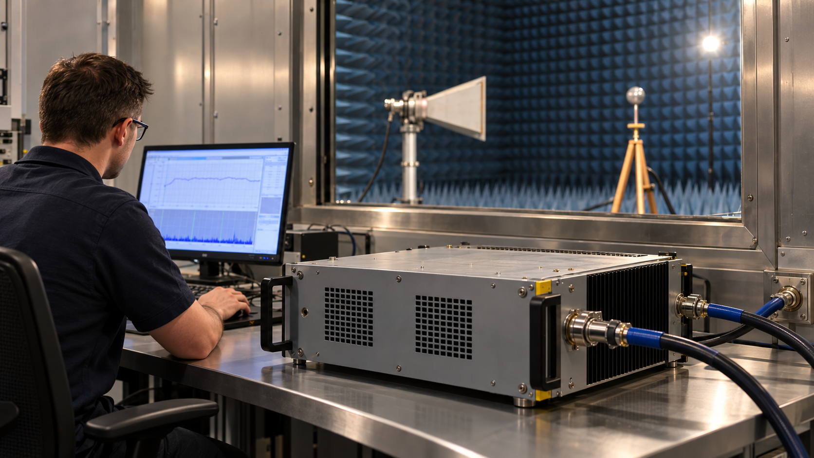
To size an EMC amplifier, calculate the PA output required at each test frequency using the field target, antenna gain, and installed RF-path losses. Check whether the PA can deliver that output linearly under the planned waveform and thermal conditions, then verify the field on site. A 50 W or 100 W rating alone cannot guarantee 10 V/m.
In radiated immunity testing, an EMC amplifier is the RF power stage driving a transmitting antenna, not the low-noise preamplifier used for emissions measurements.
Antenna gain changes with frequency, and the installed RF path adds loss. Modulation and heating can further limit usable PA output, so a single wattage estimate may miss the field target or lead to unnecessary oversizing.
The test plan must define the field requirement and geometry before an amplifier catalog becomes useful.
1. Define the Radiated Immunity Field Requirement Before Sizing the Amplifier
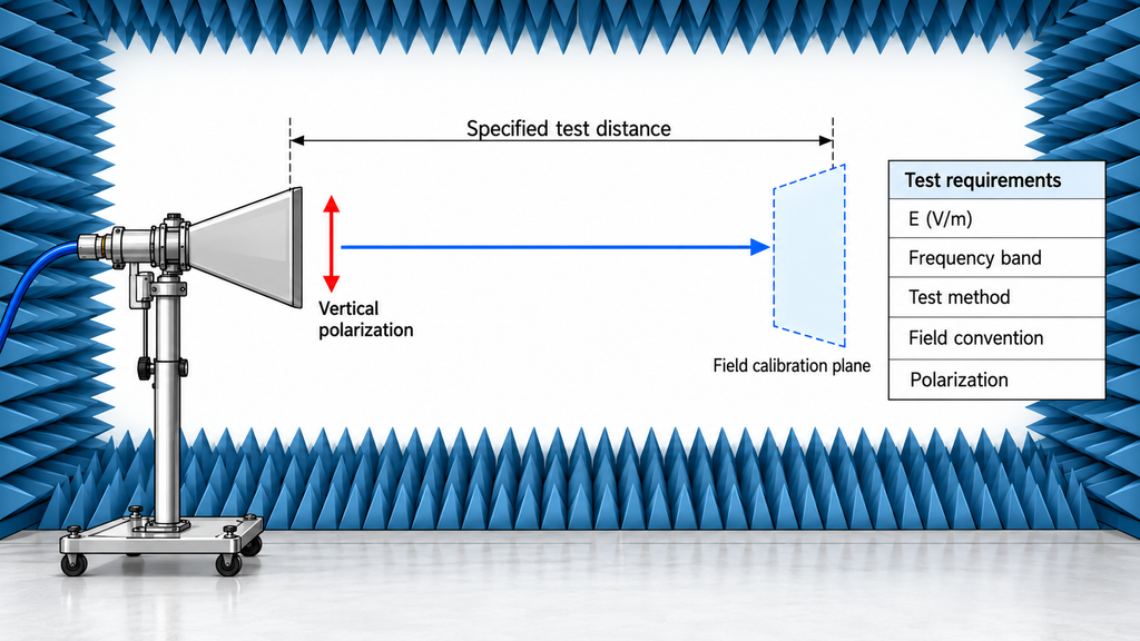
Record the target field in V/m, the frequency range, and the test standard with its edition. State whether the field level refers to an unmodulated carrier, a modulated field, or another defined condition. That choice changes the later linear-power calculation.
For example, a test under an applicable edition of IEC 61000-4-3 needs a defined antenna-to-calibration-plane distance. The plan must also state the field area, antenna orientation, polarization, and calibration method. The product’s test plan determines the level, band, and geometry. Do not infer them from a generic “10 V/m” request.
Under ideal far-field assumptions, doubling the distance requires four times the antenna-side power. Use the calibration distance specified by the test geometry, not an approximate measurement from the antenna stand to the equipment under test.
The result should be a field requirement for each relevant frequency and polarization. If the field convention or geometry is unclear, hold the amplifier choice until the test engineer confirms it.
2. Calculate the Antenna Power Needed for the Target Field Strength
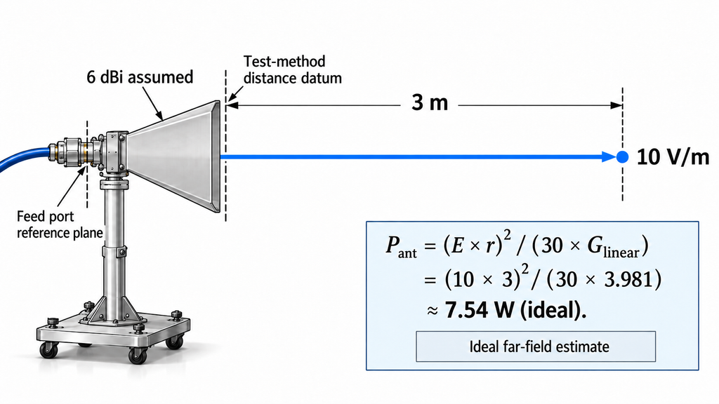
For an ideal free-space, far-field estimate, use:
P_ant = (E × r)² / (30 × G_linear)
Here, P_ant is antenna-side power in watts. E is the RMS field in V/m at the target point, and r is the distance in meters. G_linear is antenna gain in linear form for the relevant direction and polarization. Convert dBi using G_linear = 10^(G_dBi/10).
Consider an illustrative requirement of 10 V/m at 3 m with an assumed 6 dBi antenna gain:
- Linear gain: 10^(6/10) ≈ 3.981.
- Ideal antenna-side power: (10 × 3)² / (30 × 3.981) ≈ 7.54 W.
The 7.54 W result is an antenna-side starting point based on ideal far-field behavior, the stated directional gain, and a matching power reference. It excludes feeder loss, chamber reflections, field uniformity, modulation, and PA linearity, so it cannot serve as a PA specification.
Use gain at the actual frequency, direction, and polarization. A peak value at one point cannot replace the full gain curve. Check whether the source reports gain relative to power accepted by the antenna or realized gain that includes mismatch. This determines how to account for reflected power later.
3. Translate Antenna Power Into Required PA-Port Output
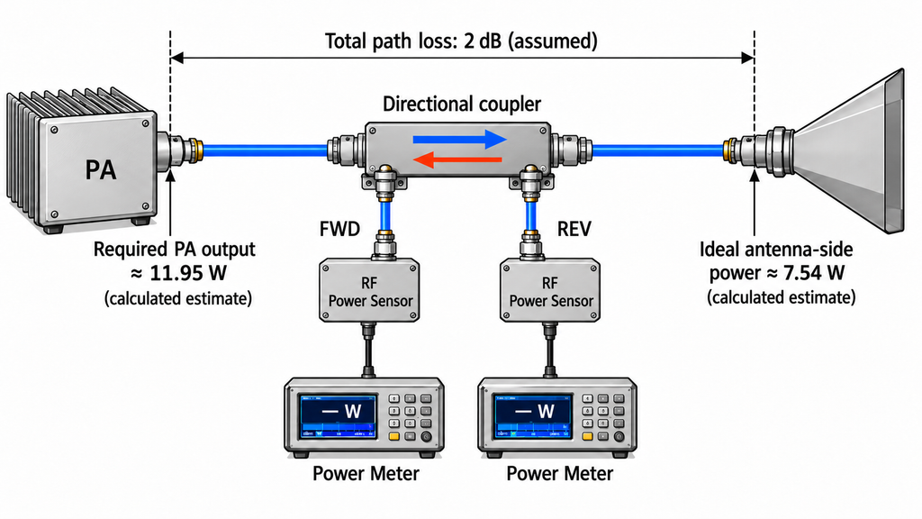
Downstream loss raises the power required at the PA output connector. For a reasonably well-matched path, use this first estimate:
P_PA,out ≈ P_ant × 10^(L_path/10)
Here, P_PA,out is power at the defined PA output reference plane. L_path is the loss in dB between that plane and the antenna input. Include the measured cable, connector, switch, and coupler losses that apply. Avoid an unexplained “system loss” allowance.
Continue the same illustrative 10 V/m calculation. If the post-PA path has an assumed 2 dB loss:
P_PA,out ≈ 7.54 W × 10^(2/10) ≈ 11.95 W.
The illustrative unmodulated budget is about 7.54 W at the antenna-side reference and 11.95 W at the PA output port. Modulation, usable linear power, and field calibration still need to be checked; neither figure is a tested requirement for a specific PA.
Mismatch needs its own treatment. Forward power at the PA port, net power accepted by the antenna, and radiated power are different quantities. If realized gain already includes mismatch, do not subtract that loss again. If gain is based on accepted power, the mismatch may need a separate correction.
With high reflected power, simple dB addition may fail. Record the forward and reverse power reference planes, antenna match, and any PA foldback or protection response. A PA tested into a matched dummy load may behave differently on the installed feeder and antenna. Compare the dummy-load and antenna-path conditions before treating their power readings as equivalent.
4. Build a Frequency-by-Frequency EMC Amplifier Power Budget
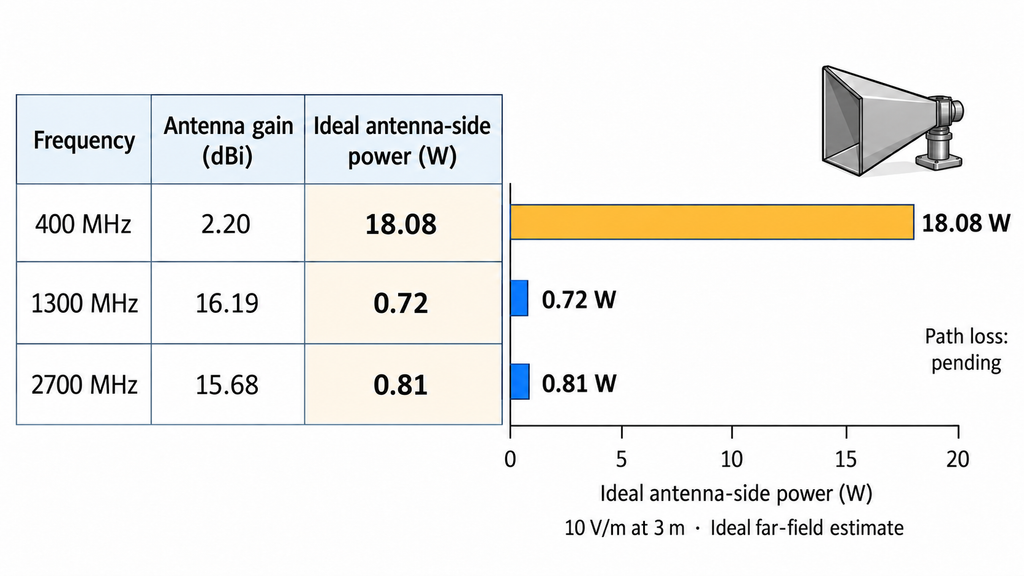
Check usable PA-port output against demand at every required frequency. The highest-demand point sets the sizing floor, but average antenna gain or one favorable measurement cannot identify it when gain and path loss vary across the band.
The table uses published gain points from RF SKYPOWER’s 300–2700 MHz antenna specification and test report to estimate antenna-side power for a hypothetical 10 V/m at 3 m requirement. These ideal free-space calculations exclude installed path loss and mismatch; they are not measured PA output or field strength.
Before applying the results to a 3 m setup, check whether the antenna satisfies the far-field condition at each frequency. The PDF labels the data only as Gain (dBi), without clearly stating whether mismatch is included. Until those points are resolved, use the table for screening; the report does not qualify this antenna for a specific EMC test chain.
| Frequency | Target V/m | Distance | Antenna gain dBi | Path loss dB | Ideal-model antenna-side power W | PA-port power W | Linear / calibration evidence status |
|---|---|---|---|---|---|---|---|
| 400 MHz | 10 | 3 m | 2.20 | Not supplied | ≈18.08 | Pending path-loss data | PA linear output and chamber field not verified |
| 1300 MHz | 10 | 3 m | 16.19 | Not supplied | ≈0.72 | Pending path-loss data | PA linear output and chamber field not verified |
| 2700 MHz | 10 | 3 m | 15.68 | Not supplied | ≈0.81 | Pending path-loss data | PA linear output and chamber field not verified |
At 400 MHz, the ideal antenna-side requirement is about 25 times the 1300 MHz estimate. The 16.19 dBi value belongs to 1300 MHz and cannot represent a minimum across the band.
The published gain table starts at 400 MHz, although the stated antenna range begins at 300 MHz. These three rows cannot identify the worst-case point across the full 300–2700 MHz band. Nor do sample gain results guarantee every delivered unit will match them.
To complete the PA budget, add measured or approved path loss at each frequency. Confirm the gain reference and mismatch treatment, then calculate PA-port output on the same basis. Compare each result with usable linear output under the planned waveform and thermal conditions. Leave missing loss and power data marked as pending.
The limiting frequency may change with the cable, switch, antenna position, or field calibration. Record the provisional worst case and the evidence still missing. Do not select a model until the full required band can be assessed.
5. Allow for Modulation Peaks and Usable Linear Power
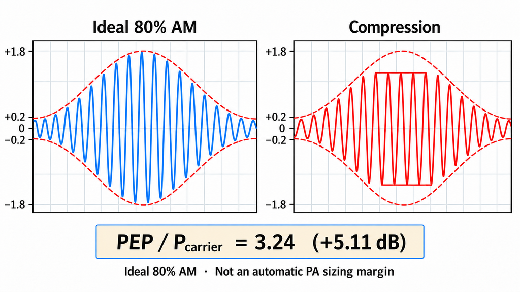
The unmodulated power budget is only a starting point. Amplitude modulation raises envelope peaks, which a PA operating near compression may distort.
For ideal sinusoidal 80% amplitude modulation (AM), the peak-envelope power relative to the unmodulated carrier is:
PEP / P_carrier = (1 + 0.8)² = 3.24, or approximately 5.11 dB above the carrier power.
The 3.24 ratio compares peak-envelope power with unmodulated carrier power; it does not call for an automatic 5.11 dB increase in every EMC setup. Check the field-level convention, calibration method, and modulation procedure. The test plan may already account for the carrier level, and applying the factor twice can oversize the PA.
Compare the waveform with the power the PA can deliver linearly. Rated CW output, the 1 dB compression point (P1dB), saturated output (Psat), and modulated peak power mean different things. A supplier’s wattage claim is useful only when its test basis matches your need.
Ask for measured output at the required frequencies and actual input drive at the PA input reference plane. Record supply voltage, load, cooling, thermal state, and test duration. Where relevant, review harmonics and waveform distortion. A short cold-state reading may not represent stabilized output.
Usable output must cover the calculated PA-port demand while meeting the project’s linearity criteria. Ask for defined RF amplifier test conditions before comparing P1dB or CW figures from different suppliers.
6. Check the Candidate Amplifier Against the Actual Test Chain
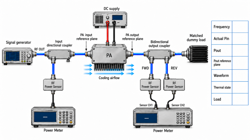
Evaluate candidates under the same test conditions: PA-port output and actual input drive across the required band, waveform and compression, hot-state output, mismatch response, and cooling. Confirm that the antenna, feeder, and connectors can handle the expected power; an antenna’s maximum rating does not establish usable linear PA output.
Use three evidence states. Comparable means frequency, reference plane, waveform, thermal state, and load conditions align well enough to apply the project’s limits. Partially Comparable means some conditions match but gaps remain. Not Comparable Yet means key data are missing or the definitions conflict. Comparing one supplier’s Psat with another supplier’s modulated linear output is one example. These states assess the evidence, not product PASS or FAIL.
Request full-power results at the required frequencies. Each result should state actual PA input power, the PA output reference plane, and the test conditions. A generator setting is not actual PA input power. A matched-load result also cannot prove installed antenna-path behavior.
RF SKYPOWER’s RF power amplifier module specifications can help identify candidate families by band and nominal power. They do not verify a particular EMC field level or modulation performance. Hold the model choice until the missing project data are available.
7. Validate the Required Field With a Calibrated Probe
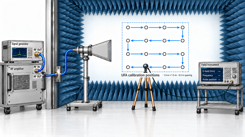
The calculated RF-port budget does not establish field strength in the actual test site. Verify the installed setup with a calibrated field probe and the procedure required by the chosen test method.
Record frequency, probe position, antenna polarization, PA power, drive state, and measured field. Check the required uniform field area (UFA) at the specified positions. One point that reaches 10 V/m cannot establish uniformity.
Check the field result alongside PA linearity. If the target appears only when the PA is driven into unacceptable compression, the setup has not met its intended conditions. Reflections, antenna alignment, loss, and power corrections can shift the measured field.
If the field is too low, return to the budget. Check gain, path loss, polarization, forward and reverse power, and PA state before raising drive. More drive cannot reliably fix mismatch or compression.
Antenna gain describes directional performance, PA testing establishes RF-port output under stated conditions, and field calibration checks field strength and uniformity in the test site. None of these proves the equipment under test passed immunity testing. Confirm RF test-chain capability against the chosen method’s field and linearity criteria.
Conclusion
Choose an EMC amplifier whose usable linear PA-port output covers the required frequencies and field levels under the specified test conditions. Build the per-frequency requirement from target V/m, distance, directional antenna gain, and real RF-path loss, with mismatch treated consistently. Then check the waveform, thermal state, and load before confirming the field through the applicable calibration.
This method gives a provisional power budget. It cannot guarantee a wattage for every 10 V/m setup, approve a model, or certify a chamber’s UFA. A peak antenna gain and the 5.11 dB relationship for ideal 80% AM are not universal sizing shortcuts.
Before requesting a quote, complete the per-frequency budget and identify missing path-loss, mismatch, linear-output, or field-calibration data. Resolve those gaps with the lab or supplier before freezing a model.
For RF SKYPOWER to review the amplifier-side requirements, send the frequency band and critical points, target V/m, carrier/modulation convention, and test method with its edition. Include distance, polarization, antenna gain and mismatch data, downstream loss, and available actual PA input drive. State the peak and linear-output needs, supply, cooling, run time, and test evidence you require. These inputs allow an engineering review of the PA specifications that still need confirmation.