











Radiated immunity testing produces defensible results when the laboratory can trace the EUT’s RF exposure to a qualified uniform field area, a calibrated forward-power reference, and a verified amplifier operating condition.
A target field strength and signal-generator setting cannot establish that exposure on their own. Engineers need the field-setting measurements, power conversion, amplifier linearity check, and equipment-under-test (EUT) observations to assess the result.
1. Which Requirements Define a Valid Radiated Immunity Test?
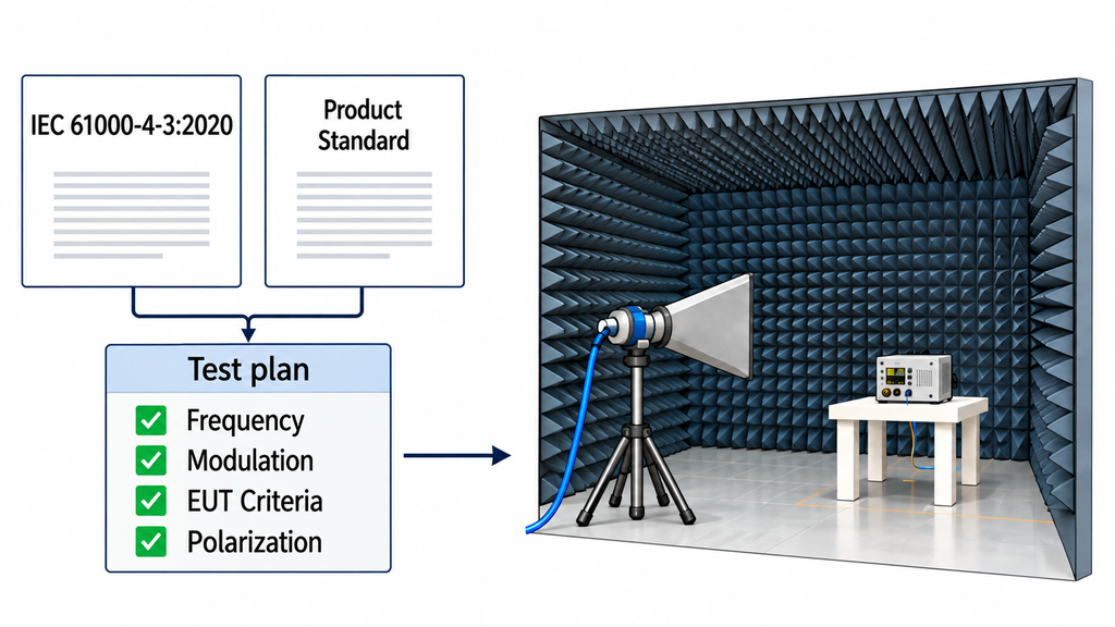
IEC 61000-4-3:2020 provides a basic method for assessing immunity to radiated radio-frequency electromagnetic fields. The applicable product or product-family standard determines how that method applies to a particular EUT.
Before testing, the laboratory must establish:
- Test frequency range and field-strength levels.
- Modulation characteristics and exposure conditions.
- EUT operating modes, monitored functions, and performance criteria.
- Test orientations, antenna polarizations, and any justified exceptions.
Under the IEC 61000-4-3:2020 reference method, the specified field strength refers to the unmodulated carrier. The test signal then uses nominal 80% amplitude modulation with a 1 kHz sine wave. The applicable product standard may prescribe different modulation or additional conditions.
The laboratory must define acceptable EUT behavior before exposure. A device may continue operating while showing a temporary change that breaches its performance criteria.
The signal generator, amplifier, coupler, antenna, and field probe form the EMC test equipment chain. Calibration records and EUT observations show whether that equipment supported the required test method.
2. How Is the Uniform Field Area Verified Before Testing?
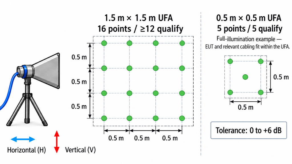
The uniform field area (UFA) is the calibrated region used to expose the EUT. The laboratory establishes it before placing the EUT in the test position.
For a conventional 1.5 m × 1.5 m UFA, the calibration grid contains 16 points arranged in four rows and four columns. At least 12 points must meet the applicable 0 dB to +6 dB uniformity criterion at each calibration frequency.
Under full illumination, the laboratory may use a smaller UFA when the EUT and its relevant cabling fit within the calibrated area. The minimum 0.5 m × 0.5 m UFA contains five points: four corners and one center point. All five must meet the uniformity requirement.
The 75% acceptance rule for larger UFAs does not apply to this minimum grid.
Partial illumination has separate requirements. IEC 61000-4-3:2020 Table 3 defines the minimum UFA dimensions by frequency range and illumination method. For partial illumination up to at least 1 GHz, the minimum UFA is 1.5 m × 1.5 m. The 0.5 m × 0.5 m minimum is therefore not a universal option for partial illumination.
Field characterization uses an unmodulated carrier in both horizontal and vertical antenna polarizations. The transmitting antenna must be at least 1 m from the UFA, with 3 m preferred.
Record the antenna-to-UFA distance using the reference point specified for that antenna type. Maintain the same distance during EUT testing.
The UFA record must identify the grid dimensions, calibration plane, measurement points, field levels, antenna configuration, both polarizations, and qualifying results. The selected illumination method must cover the required EUT and cabling areas.
Grid placement must follow the selected standard edition. A fixed lower-edge height from an older procedure should not be carried into a 2020-edition setup without checking its applicability.
The gain and beamwidth of a broadband horn antenna influence how the calibration plane is illuminated. The measured grid results establish whether the selected area meets the uniformity requirement.
A passing UFA result supports the field-setting configuration. The laboratory subsequently uses that calibration to determine the power required for EUT exposure.
3. What Does a Calibrated Field Probe Actually Verify?
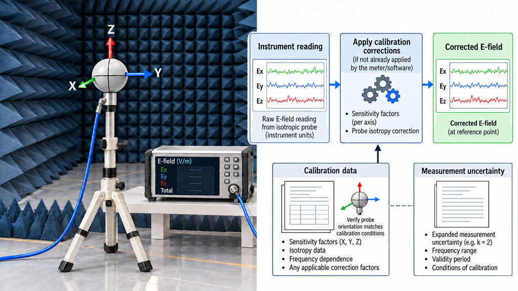
A field probe measures the electric field during UFA calibration and field level-setting. A suitable isotropic probe accounts for the field components along three orthogonal axes.
The laboratory must use the probe’s calibration information when interpreting its readings. This includes frequency-dependent correction factors, measurement uncertainty, and applicable orientation conditions.
Keep three records distinct:
- Instrument reading: the value reported by the probe or its software before any separately applied correction.
- Corrected field value: the result used for field-setting decisions after applying the relevant corrections.
- Calibration evidence: the certificate, validity information, correction data, and uncertainty supporting the measurement.
Some probe systems apply correction factors internally. Others require separate data processing. The record should state which method was used so the same correction is not applied twice.
Probe orientation must agree with its calibration conditions. The laboratory should not assume that a different mounting orientation produces an equivalent response.
The field-setting probe is normally removed from the calibrated location during EUT exposure. The test then uses the validated field-setting procedure and RF power reference. Earlier probe measurements provide the calibration basis, while the power-control records document the subsequent exposure setting.
4. How Does Forward-Power Calibration Set the Test Field?
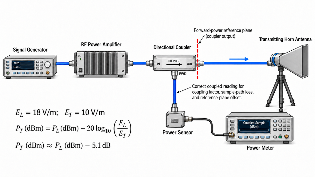
The RF path normally runs from the signal generator through the power amplifier and directional coupler to the transmitting antenna.
Where a directional coupler and separate power sensor are used, the coupled sample reaches the calibrated sensor. The sensor reports its measurement to the power meter. Other calibrated forward-power monitoring arrangements are possible.
The signal-generator setting, amplifier input power, amplifier output power, and measured forward power refer to different quantities. The laboratory must identify the reference plane and applicable losses for each measurement.
IEC 61000-4-3:2020 distinguishes the field-setting level from the level required during EUT exposure:
- E_T: the specified test field strength of the unmodulated carrier.
- E_L: the field strength used during field level-setting.
- P_L: the forward power established during level-setting at E_L.
- P_T: the calculated forward-power reference for the unmodulated carrier during EUT testing.
For the reference 80% AM method, field level-setting uses an unmodulated carrier at an E_L of at least 1.8 times E_T.
The forward-power relationship is:
P_T (dBm) = P_L (dBm) − 20 × log10(E_L / E_T)
Both power values must refer to the same defined forward-power measurement reference plane. Where readings come from different planes, the laboratory must account for the relevant path losses and calibration factors before comparing them.
When E_L is exactly 1.8 times E_T:
P_T = P_L − 5.1 dB (approximately)
For a 10 V/m test level, the laboratory can use an 18 V/m level-setting field. The forward power established at 18 V/m is then approximately 5.1 dB above the calculated 10 V/m carrier-power reference.
This calculation applies to the unmodulated carrier. The laboratory adds the required modulation during EUT exposure according to the selected method.
Retain the measured P_L, calculated P_T, frequency, measurement reference plane, path corrections, and power-control method. If a report includes a power reading taken with modulation applied, identify it separately from the unmodulated carrier reference.
5. How Is Amplifier Linearity Checked at the Required Test Level?
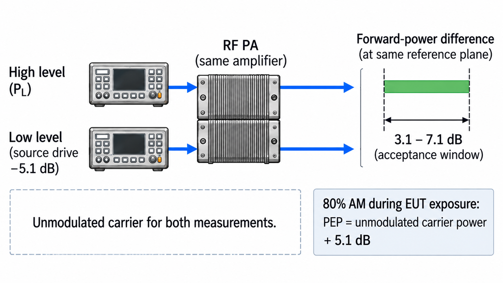
The amplifier must produce the required RF exposure within the linearity conditions allowed by the test method.
Its nominal output-power rating is insufficient evidence. Gain may change with frequency, output level, load conditions, and temperature. A single P1dB value cannot establish linear operation across the full immunity test range.
Amplitude modulation increases the required peak-envelope capability.
For ideal 80% AM:
Peak-envelope power ratio = (1 + 0.8)² = 3.24
The peak-envelope power is therefore approximately 5.1 dB above the unmodulated carrier power. This relationship concerns peak-envelope power and must not be applied indiscriminately to other power measurements.
IEC 61000-4-3:2020 includes a linearity check in its field level-setting procedure.
Where E_L = 1.8 E_T, the laboratory reduces the signal-generator output by 5.1 dB from the setting used to establish P_L. The measured forward-power reduction must fall between 3.1 dB and 7.1 dB for the amplifier to satisfy that check.
These limits apply to the specified procedure. Different modulation schemes or operating conditions may require a different assessment.
An EMC amplifier power budget must account for the calibrated RF path and required linear operating point. The laboratory still needs measured level-setting and linearity results at the relevant frequencies.
For simultaneous multi-signal testing, the assessment must also cover aggregate drive and unwanted signal products. Single-tone UFA measurements alone do not establish multi-signal suitability. Harmonic and intermodulation checks must follow the applicable method.
Where the required measurements are missing, amplifier suitability remains unverified.
6. What Must Remain Controlled During EUT Exposure?
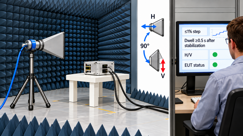
Verify the test system before exposing the EUT. Earlier calibration results do not establish that the equipment is operating correctly on the test day.
A field-strength check at one or more UFA points and frequencies can help confirm the setup. The laboratory must also verify the EUT’s correct operation under the defined reference conditions.
During exposure, apply the required test-power reference and modulation while monitoring the EUT in its specified operating modes.
Under IEC 61000-4-3:2020, incremental frequency steps must not exceed 1% of the preceding frequency. This limit applies to both field level-setting and EUT testing.
Dwell time starts after the test condition has stabilized. It must be at least 0.5 s and long enough for the EUT to respond.
A longer dwell time may be needed for slowly responding functions. A short interval can miss errors that appear only after a control cycle, communication exchange, or delayed system response.
The exposure plan must cover the required EUT faces and both horizontal and vertical antenna polarizations. Any reduced orientation set or other exception needs technical justification under the applicable method.
Monitoring must follow the defined performance criteria. Relevant observations may include communication loss, unexpected state changes, degraded measurements, output interruptions, recovery behavior, or operator intervention.
The exposure log should identify the applied power reference, frequency steps, dwell time, modulation, antenna orientation, and EUT operating mode. Record relevant event timing, deviations, interruptions, and retests.
A test can show no visible alarm while an unmonitored function degrades. The final assessment must therefore connect observed behavior to the agreed performance criteria.
7. When Does a Setup Change Require Revalidation?
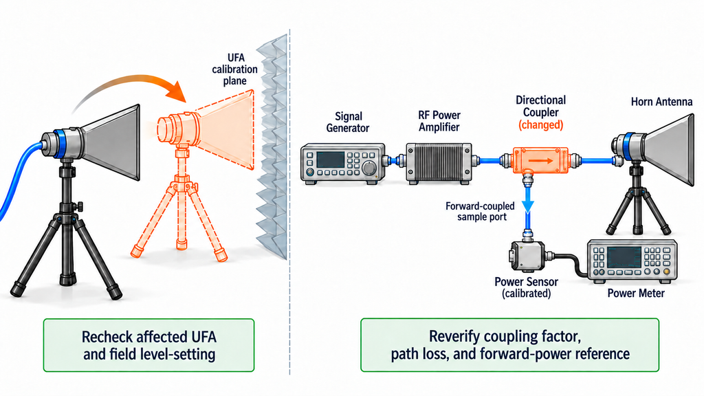
Calibration evidence applies to a defined physical and measurement configuration. A change can alter the relationship between forward power and field strength within the UFA.
IEC 61000-4-3:2020 envisages full field level-setting at least annually and after relevant changes to the enclosure configuration. Changes elsewhere in the RF path may also require verification before further testing.
Examples include moving an antenna, rerouting a cable, replacing the power amplifier, changing the directional coupler, or updating field-probe correction data.
The necessary response depends on what changed. A chamber modification may affect field uniformity. A power measurement-path change may instead require updated coupling, loss, or forward-power verification.
Record the change, its date, and the earlier measurements it affects. Identify which checks must be repeated and which results remain valid.
Retain the measurement uncertainty information relevant to field measurements and level-setting. Uncertainty cannot justify a nonconforming UFA or replace a missing linearity check.
If existing evidence cannot establish the effect of a change, repeat the affected calibration or verification before using the setup for another immunity test.
8. What Calibration Evidence Should a Radiated Immunity Test Report Contain?
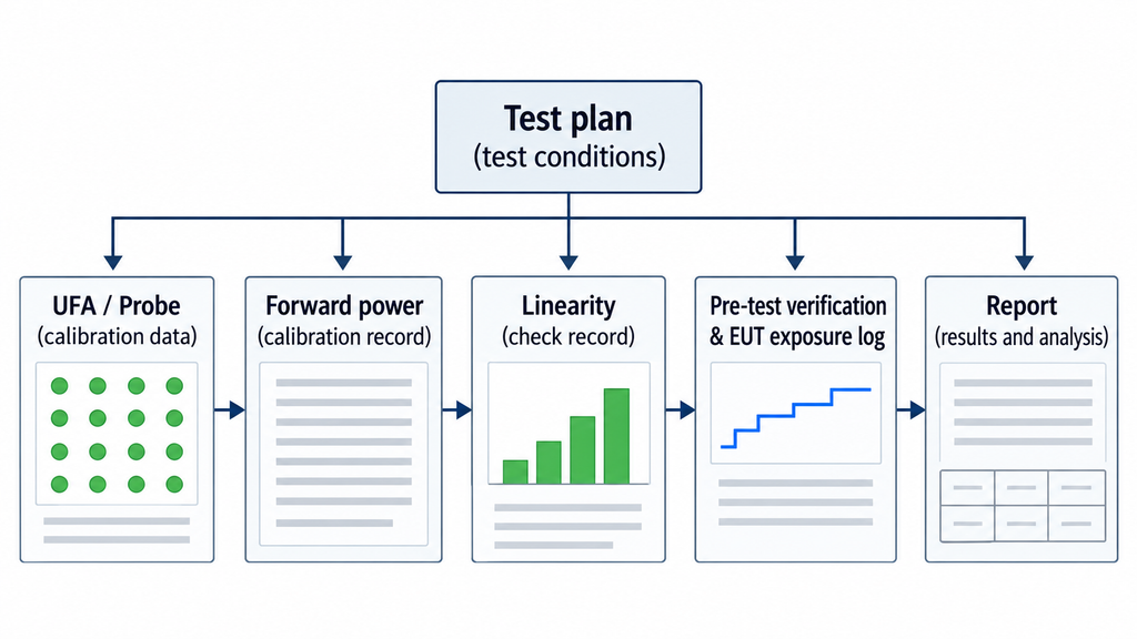
A defensible radiated immunity report links the approved method, calibrated RF exposure, and observed EUT performance. Each stage supplies evidence for a specific part of the result.
| Review stage | Minimum record to retain | What the record supports | What it does not prove |
|---|---|---|---|
| Test plan | Standard edition, frequency range, levels, modulation, EUT and test-equipment identification (including model and serial number), EUT and cable layout, relevant environmental conditions, and performance criteria | Defines the required exposure conditions, equipment identity, physical setup, and assessment basis | That the laboratory applied those conditions |
| UFA verification | Illumination method, grid dimensions, point locations, both polarizations, antenna-to-UFA distance, frequency-specific corrected field results, and acceptance outcome | Shows that the selected calibration area met its applicable uniformity requirement | The exact field around the EUT at every moment of exposure |
| Field probe | Calibration certificate, correction factors, uncertainty, validity, and applicable orientation | Supports the traceability of the field measurements | That probe corrections were applied correctly without an accompanying measurement record |
| Forward-power setting | E_L, E_T, measured P_L, calculated P_T, reference plane, path corrections, and frequency | Connects the calibrated field-setting condition to the EUT test-power reference | That a generator setting alone produced the required field |
| Amplifier linearity | Test frequency, relevant generator settings, measured forward-power values, and linearity-check result | Supports the required linear operating condition at the checked points | Linearity at untested frequencies, levels, or modulation conditions |
| EUT exposure | Pre-test system and field checks, frequency sweep, dwell, modulation, polarization, EUT face, applied power reference, and monitored behavior | Documents the test-day system verification, exposure performed, and EUT response observed | Performance of unmonitored functions or configurations |
| Final result | Observed effects and duration, performance assessment, pass/fail rationale, deviations, retests, and report references | Supports the reported outcome for the tested EUT and conditions | Acceptance of other EUT configurations or RF systems without further evidence |
This matrix supports evidence review; the formal report must still meet the requirements of the applicable standard and laboratory quality system.
IEC 61000-4-3:2020 Clause 10 requires sufficient information to reproduce the test. That includes equipment identification, relevant environmental conditions, observed EUT effects and their duration, the decision rationale, and descriptions or photographs of the test setup.
A reviewer should be able to trace a reported test point from the EUT response back through the applied power reference, linearity check, field-setting results, and probe calibration. Missing evidence should be resolved before relying on the reported exposure condition.
Conclusion
A radiated immunity result is supported when the laboratory can trace its field-setting data, forward-power reference, amplifier linearity, and EUT observations to the same test configuration.
That evidence supports the reported outcome under the tested conditions. Other amplifier, antenna, feed-path, or EUT arrangements require their own supporting measurements before an equivalent result can be claimed.
Before accepting a report or selecting an RF amplifier, compare the UFA, probe, forward-power, linearity, pre-test verification, and exposure records at the required frequencies. Request clarification wherever measurements or reference planes cannot be reconciled.
For an RF SKYPOWER amplifier review, provide the required frequency range, target field strength, modulation, calibrated power data, antenna and feed-path conditions, available drive, PA-output reference plane, cooling conditions, and relevant test evidence. You can request a condition-specific amplifier review to identify the model data and further verification needed before making a selection or acceptance decision.