










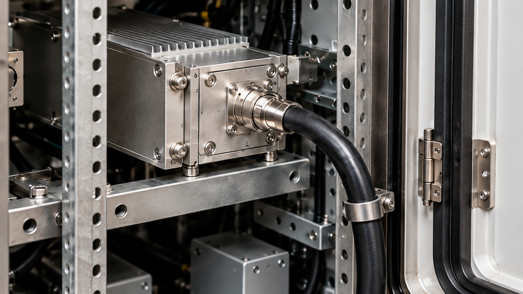
RF output connector orientation in a C-UAS cabinet should be defined before the layout is frozen: establish the RF PA output datum, cable exit vector, and clocking reference, then check the complete assembly envelope against the actual cabinet and service conditions. A straight, angled, or clocked option can be judged only when the PA and connector drawings, cable assembly limits, and cabinet boundaries describe the same interface; no angle or bend radius works as a universal answer.
A connector can clear a panel opening and still conflict with an adjacent component, the cable transition, a mating tool, or a closed door. The project-specific drawings and component data needed to settle those details are not available here, so this article gives a decision method rather than dimensions or a fit conclusion. Freeze the reference first, then compare the physical envelope and planned assembly actions. Local connector clearance is one input to a broader C-UAS cabinet layout clearance assessment, which considers full-cabinet integration boundaries.
1. Define the PA output datum, exit vector, and clocking reference
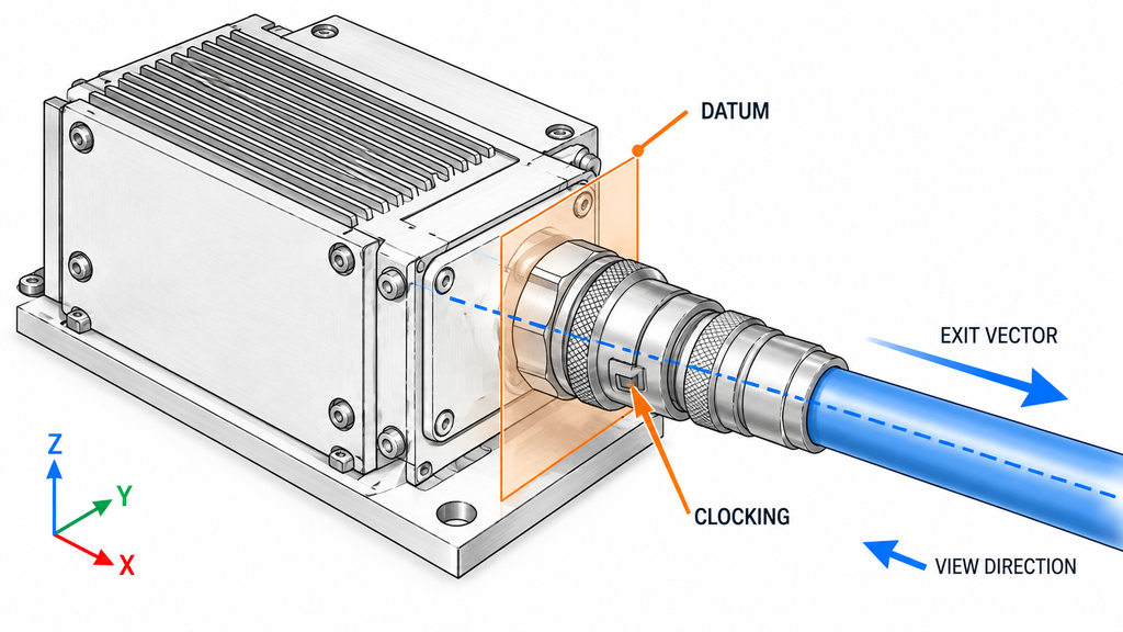
“Point the connector down” is not a drawing definition. Its meaning changes with the view, coordinate system, and side from which someone observes the interface. A datum is the stated mounting surface or axis used as the reference; the drawing should also identify relevant local axes and the viewing direction used to describe orientation.
From that reference, record the cable exit vector, meaning the direction in which the cable leaves the interface, and any clocking reference mark. Clocking describes rotational position around a stated axis; it does not mean every connector can rotate after installation. Whether rotation is allowed, and any permitted position or tolerance, must come from the specific PA and connector documentation. Do not infer adjustability from a drawing view or from an angled connector’s appearance.
This definition lets design, procurement, manufacturing, and installation teams compare the same physical direction. If two drawings use different views, translate them to one coordinate reference before comparing labels such as “left,” “right,” or “down.” If a missing datum or uncertain clocking feature could change the candidate choice, hold the decision and request the current interface drawing.
Record the drawing number and revision alongside the datum, view, exit vector, and clocking mark. That way, a later drawing update does not silently change the meaning of an approved orientation.
2. Measure the connector body and full installation envelope
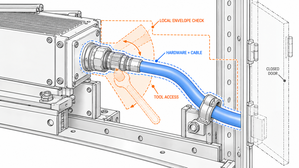
A panel-port measurement captures only one boundary. The installation envelope must include the connector body and coupling hardware, any fixed transition behind the connector, the cable section before its first bend, planned support, mating-tool access, service movement, neighboring hardware, and the door or cover in its closed position.
Build that envelope from the actual component drawings and cabinet model. Connector length, a semi-rigid transition, a cable’s permitted straight section, and tool clearance belong to different sources; a single outside dimension cannot stand in for all of them. Mark each value with its source and revision. If a dimension that could change the selected direction is missing, label it unresolved rather than treating the space as clear.
A manufacturer’s installation-envelope guidance can show why connector length, cable bend limits, and the straight section before bending must be considered together. Those values remain specific to the documented assembly. They do not establish a general clearance or prove that a different cable and connector combination will fit.
Overlay the connector and cable assembly on the cabinet boundaries using one mounting datum. Check interference with the panel, nearby components, door travel, and the route needed for later access. If the decision expands beyond the output interface, include adjacent hardware, service access, airflow, DC, and control clearances in the broader cabinet assessment. An undecided cable construction leaves the envelope open; complete RF PA feeder cable selection before treating its bend and transition limits as fixed inputs.
The useful output from this step is a sourced envelope drawing or model, with unknown dimensions visible.
3. Compare straight, angled, and clocked connector options against the same envelope
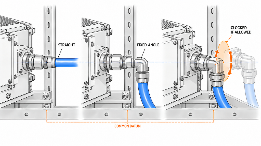
Compare real candidate assemblies, not angle labels. A straight connector, a fixed-angle connector, and a connector with an allowed clocking adjustment may occupy different space once their coupling hardware, transition, cable, and service actions are included. The same cabinet boundary and mounting datum must apply to every candidate.
For each candidate, use the same fields: interface compatibility, exit vector, body dimensions, transition geometry, cable assembly, clocking limits, first-bend constraints, mating access, and closed-door condition. Note which drawing or installation document supports each field. If one candidate lacks a critical dimension, it is not ready for an unconditional ranking. Mark it “not comparable yet” and request the missing evidence.
An angled option may be worth evaluating where space is constrained, but that observation does not make a particular angle the best choice for every cabinet. Manufacturer guidance for a specific assembly supports only that product family and its stated conditions. Orientation alone also does not establish lower insertion loss, improved return loss, or any other RF performance result.
The visually shortest option can move interference to the connector body, cable transition, or tool path. Rejecting a candidate is therefore as useful as selecting one, provided the reason points to a documented constraint. If a symptom points to a crimp or termination fault, isolate it through RF PA connector termination diagnosis; connector orientation alone cannot identify the defect.
4. Check the first bend, cable support, and load path
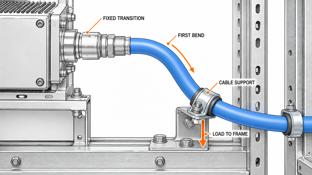
After comparing connector geometry, follow the selected cable from its exit point through the first bend and to its planned support. The cable assembly’s current manufacturer data must define applicable bend limits and any straight transition required behind the connector. Static and dynamic conditions can differ, so do not carry a value from one condition into another without documentation.
No universal bend radius can settle this check. Cable constructions and assembly details differ, and a number from another product instruction does not become a project rule. Use the data for the exact cable assembly and note its revision. If the cable has not been selected, or its first-bend limits are unavailable, keep the orientation decision conditional.
The drawing or model should show where the first bend begins and where support carries cable weight or movement. Avoid a layout that depends on twisting the cable to make an orientation fit, pinching it against a panel, or leaving the connector to carry unsupported cable load. These are mechanical checks; do not turn them into a predicted loss or VSWR change without evidence for the actual installation.
Once the direction is fixed, evaluate RF PA cable bending and loss on the complete installed route rather than inferring it from the connector drawing. If cable grade remains open, keep its bend and support limits unresolved instead of freezing the connector direction.
5. Verify mating, tool access, service space, and the closed-door condition
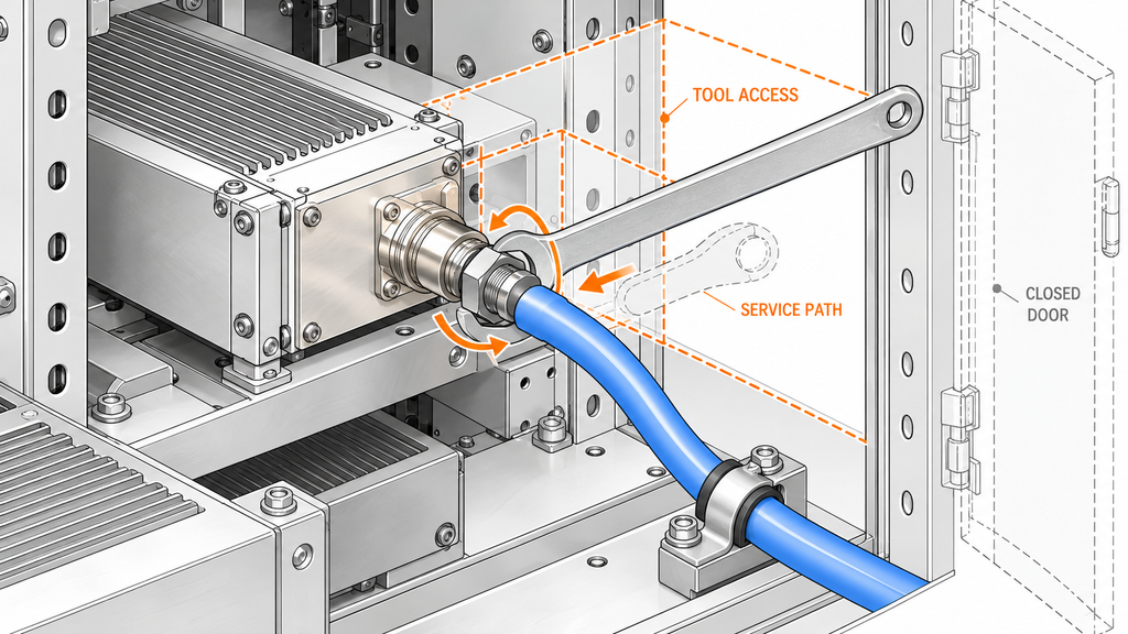
A connector may fit inside a cabinet and still be impossible to mate, tighten, or service in the planned sequence. Review the actual coupling method and required tool movement, then verify that adjacent parts leave enough room for the technician’s hands or tool. Include any support needed while mating or disconnecting the assembly.
Next, check the service action that the design expects: inspection, disconnection, replacement, or another defined task. Do not assume a tool that fits during initial assembly will remain usable after neighboring parts are installed. The required access depends on the connector, the chosen tool, and the cabinet arrangement, so a generic clearance value cannot replace the component instructions and project model.
Finally, evaluate the assembly with the door or cover closed and the cable in its supported final position. An open-door view does not prove that the cable clears the closed panel, hinge sweep, latch, or nearby hardware. If the door would press on the cable, or a required service action cannot be completed, return the candidate for a direction or layout change before freezing the drawing.
This local check does not approve the entire cabinet or verify an installed RF path. A broader cabinet-level fit issue belongs with the layout review. Installed-route identity and acceptance require C-UAS cabinet RF path verification, which the connector-orientation record cannot replace.
6. Freeze the orientation decision in a drawing and RFQ record
Once a candidate has been reviewed against one datum, one component set, and one cabinet boundary, capture the decision in a versioned record linked to the interface drawing and RFQ. The record below is a practical engineering aid, not a standard or a test report. Use “pending” wherever a dimension, limitation, or service condition still needs confirmation. Do not mark the orientation frozen if an unresolved field could change whether the assembly fits or can be serviced.
| Check item | Record value / candidate | Supporting drawing or document and revision | Status | Owner / action before freeze |
|---|---|---|---|---|
| PA datum, viewing direction, and local axes | Project-defined datum and view | PA interface drawing and revision | Pending until documented / confirmed | Mechanical or RF design owner |
| Exit vector and clocking reference; rotation permitted? | Project-defined vector and clocking | Connector or PA drawing and revision | Pending until permitted position is verified / confirmed | PA or connector supplier |
| Connector body, coupling hardware, and fixed transition envelope | Candidate-specific dimensions | Connector assembly drawing and revision | Pending until complete / confirmed | Connector supplier |
| Cable assembly model and complete installation envelope | Candidate cable assembly | Cable assembly drawing or datasheet revision | Pending until selected / confirmed | Cable supplier or RF design owner |
| First-bend limit, straight transition, and support point | Candidate-specific limits and locations | Cable assembly installation data | Pending until documented / confirmed | Cable supplier and mechanical design owner |
| Mating direction, coupling tool access, and assembly sequence | Planned operation and tool path | Connector instructions and assembly plan | Pending until reviewed / confirmed | Manufacturing or integration owner |
| Service or removal access | Project-defined service action | Cabinet service model or procedure revision | Pending until demonstrated / confirmed | Service and mechanical design owners |
| Neighboring hardware and cabinet boundary | Project-specific interference boundary | Cabinet model or drawing revision | Pending until checked / confirmed | Cabinet design owner |
| Closed-door or cover condition with cable supported | Final supported condition | Closed-state model, mock-up, or inspection record | Pending until checked / confirmed | Integration owner |
| Drawing/RFQ revision, unresolved evidence, and responsible party | Current decision status | Interface drawing and RFQ revision | Not frozen / frozen | Assigned owner and pre-freeze action |
Use the record to make the comparison traceable: each candidate should refer to its own current documentation, and inputs from different revisions should not be mixed as though they describe one configuration. A candidate with an unknown dimension remains unresolved; it does not outrank a documented candidate by default. Keep the planning record distinct from later installed-path checks or RF performance acceptance.
After the direction record is complete, product discovery still needs the required frequency band, output power, and interface constraints. Buyers can then review the RF PA module product range; its catalog scope does not prove that a particular model fits the cabinet geometry.
Conclusion
Choose RF output connector orientation only after defining the PA datum, viewing direction, exit vector, and clocking reference, then checking the specific connector and cable assembly against the full installation and service envelope. The result depends on current component drawings, cable limits, cabinet boundaries, and planned assembly actions. No universal angle or bend radius resolves those project conditions, and a planning record does not verify RF performance after installation.
The most likely mistake is treating an angled connector as an automatic cure for interference or cable stress. It is only one candidate, and it can shift a conflict to another part of the envelope. Before freezing the layout, obtain missing drawings or limits, complete the record, and leave any decision-changing item marked unresolved. That gives engineering and procurement a clear basis for the next review.
RFQ and Purchasing Takeaway
For an RFQ, specify the PA and connector drawing revisions; cable assembly model and applicable bend or support conditions; datum, exit vector, and clocking reference; full installation envelope; first-bend and support details; mating tool and service access; neighboring hardware and door boundary; and closed-door check. Name missing evidence and the party expected to provide it. State separately that this record supports layout planning; final installed-path acceptance requires its own agreed method and evidence.
If interface or cabinet conditions still need discussion, contact the engineering team with the relevant drawings and component data. A product-family page does not confirm fit for a specific cabinet, and a project discussion does not guarantee a configuration, performance result, response time, or delivery commitment.