










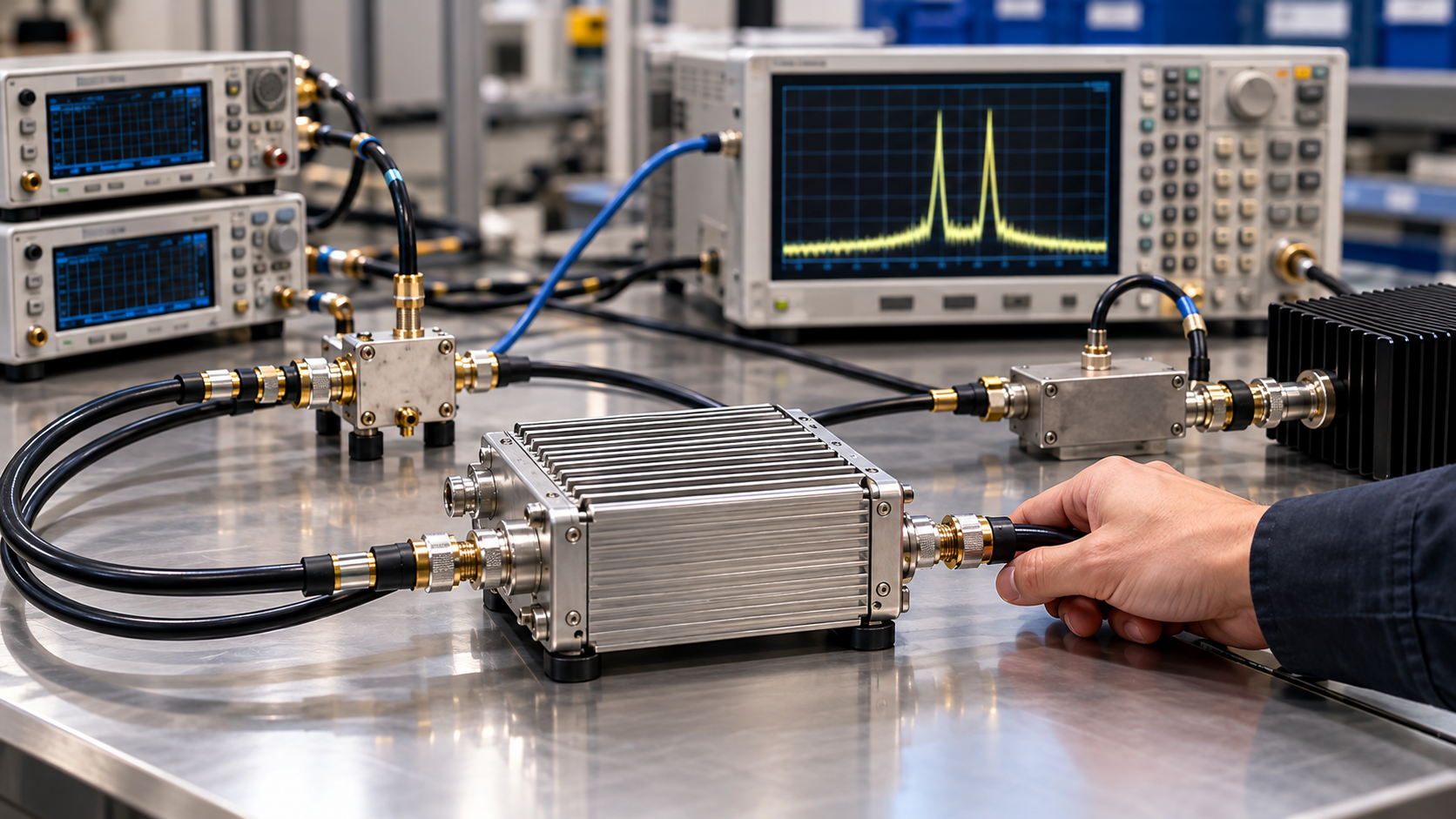
Intermodulation distortion (IMD) does not need to be a default acceptance item for every C-UAS RF power amplifier chain. It becomes a separate requirement when the project explicitly calls for a linearity measurement or, without such a requirement, when simultaneous signal components can meet at a common nonlinear node and the resulting products could affect a defined band or system decision.
The main evidence gap is usually not the definition of IMD. It is the missing test boundary: which carriers are active together, how per-tone and total power are defined, which physical points—or reference planes—Pin and Pout represent, and whether the source and receiver are clean enough to expose the device under test. Without those conditions, two suppliers can report different IMD values that are not technically comparable, or a test team can attribute a product created by the measurement chain to the PA. The first decision is therefore whether the project requires a dedicated IMD test at all.
1. When Does IMD Become a C-UAS RF PA Requirement?
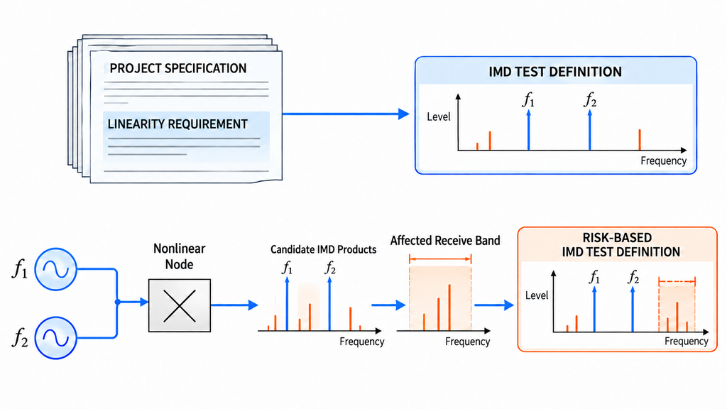
There are two valid ways for IMD to become a project requirement. The first is contractual or technical: the RFQ, system specification, or acceptance plan already calls for third-order intermodulation (IMD3), output third-order intercept point (OIP3), noise power ratio (NPR), adjacent-channel leakage ratio (ACLR), or another defined linearity result. That requirement still needs a complete method, but it does not depend on first proving that an intermodulation product will enter a particular protected band.
The second route is risk-driven. It applies when two or more signal components are active at the same time, can reach the same nonlinear element, and could create products that affect a specified receive band, adjacent channel, protected band, or system-level decision. The nonlinear element may be the PA, another active stage, a passive nonlinear junction, or even part of the measurement receiver. A frequency relationship identifies a candidate product; it does not locate the mixing element. In either route, record the PA operating point: operation closer to a nonlinear region can increase the relevance of IMD, but it does not create a universal back-off rule.
| Project requirement | Actual signal state | Common nonlinear node | Affected band or system decision | Decision | Next action |
|---|---|---|---|---|---|
| A defined linearity metric is already required | Use the simultaneous carriers or waveform stated by the project | Define the device and path being evaluated | State how the result will be used, even if no protected band is named | IMD testing is project-required | Freeze the method, metric, operating point, reference planes, and decision rule |
| No explicit metric, but multiple components operate simultaneously | Identify every active carrier and permitted combination | Identify where the components can meet nonlinearly | Identify the band, receiver, channel, or decision that could be affected | IMD testing is risk-triggered | Select a stimulus that represents the risk and define the applicable limit source |
| No explicit linearity metric is required | Carriers are verified to operate separately and do not share the nonlinear node under review | No common node is established for the stated condition | No IMD-specific decision has been defined | IMD is not the primary test for that stated condition | Retain the power, harmonic, spur, and other tests required by the project |
| No explicit metric has been confirmed | Simultaneous state, path, or decision use is unknown or incompletely recorded | Not established | Not established | The requirement is not defined yet | Hold the acceptance conclusion and complete the missing system definition |
This table decides whether an IMD task exists; it does not diagnose where a product originates. If a spectral component appears only when several modules transmit, the separate problem of multi-module spectral coupling and path isolation determines whether leakage, nonlinear interaction, or the measurement branch is the more credible next path to investigate.
2. Why IMD Is Not the Same as Harmonics or General Spurs
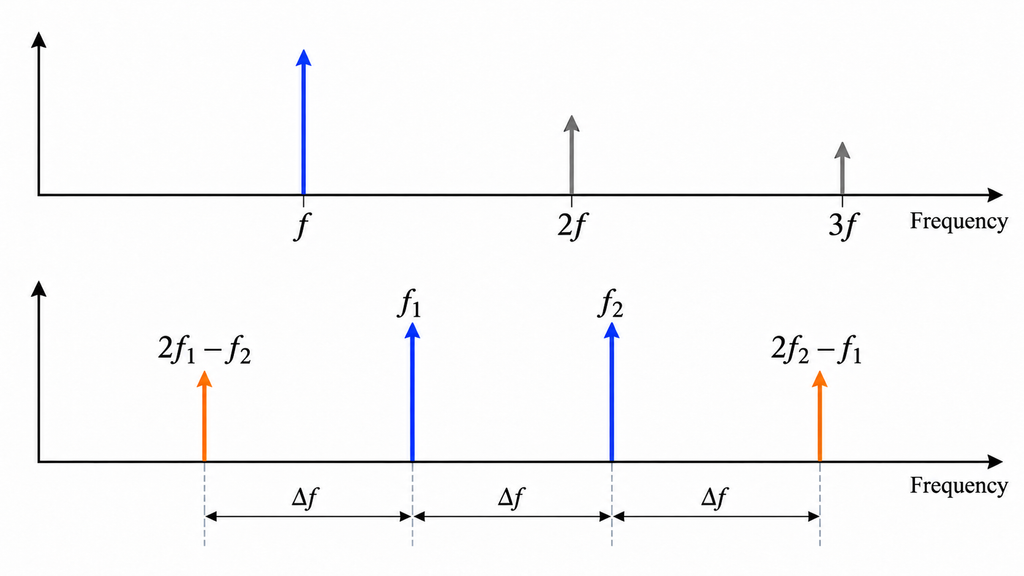
A harmonic is tied to one input frequency. For a single carrier at frequency f, the second and third harmonics occur at 2f and 3f. Intermodulation requires at least two input components. With two carriers at f1 and f2, third-order candidates include 2f1 − f2 and 2f2 − f1. These products are important because they can fall close to the wanted carriers and may not be removable with a simple output filter.
A spur is a broader observation: it is an unexpected spectral component whose source may be the signal generator, driver, PA, switching circuitry, coupling path, or receiver. Linear leakage is different again. It transfers energy that already exists; by itself, a linear path does not create a new frequency. The RF power amplifier harmonic test scope therefore answers a different question from an IMD test, even though both examine nonlinear spectral products.
The observed frequency is a classification clue, not a root-cause verdict. A line at a calculated IMD3 frequency may already be present in the source, may be created by generator interaction after combining, or may be generated inside the analyzer. A complete source, PA, and receiver spur-isolation record remains useful when the component cannot yet be assigned to the DUT. For each line, record the candidate class—harmonic, intermodulation, general spur, or leakage—the alternatives that remain open, and the next controlled check, such as a source baseline, a receiver-loading check, or PA insertion under matched conditions. Until the source frequencies, simultaneous state, and observation point are known, the correct conclusion is that the mechanism is unresolved—not that the PA has failed.
3. Define Carriers, Spacing, and Power Before the Test
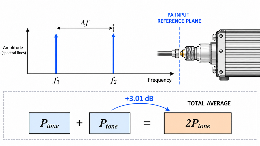
An IMD result is inseparable from the stimulus that produced it. A reproducible definition identifies the number of carriers, each carrier frequency, the spacing between them, their relative levels, and whether frequency or power will be swept. It also identifies the load, supply condition, thermal state, and whether drive is fixed or adjusted. Changing several of these conditions at once prevents the result from isolating PA behavior.
Per-tone power and total power must remain separate. For two equal-power CW tones, total average power is the linear sum of the two tone powers, approximately 3 dB above either tone by itself. That relationship does not define peak envelope power, does not describe a modulated waveform, and should not be applied when the averaging window or signal statistics are different. A phrase such as “100 W two-tone test” is therefore incomplete until the report says whether 100 W is per tone or total, whether it is Pin or Pout, and at which reference plane it applies.
Actual Pin should be defined per tone at the PA input reference plane after the applicable source-path correction. At the output, the report should distinguish each wanted tone, the combined average Pout where relevant, and the measured intermodulation products at the PA output reference plane. If the generator display is treated as Actual Pin or an analyzer-input reading is treated as PA-output power without a correction chain, the operating point is not traceable.
The same discipline used to define Pin, Pout, load, and thermal state in a swept-frequency full-power RF PA test also prevents an IMD comparison from drifting between operating points. Direct comparison is allowed only after carrier frequencies, spacing, per-tone and total power, tone balance, load, supply, thermal state, and drive rule are aligned or their differences are explicitly accounted for.
4. Set the Reference Planes and Measurement Bandwidth
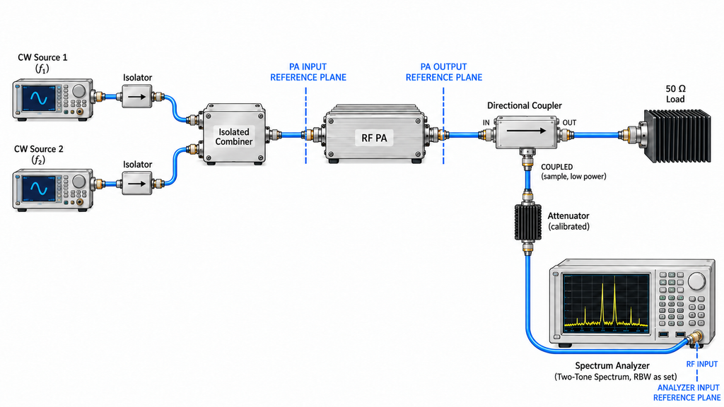
At least three reference planes should be named: the PA input, the PA output, and the analyzer input after the sampling path. The source cables, combiner or coupler, attenuators, output coupler, filters, and analyzer feed can all introduce frequency-dependent loss. Raw readings and correction terms should remain traceable so that the final tone and product levels refer to the intended PA plane rather than an undefined instrument port.
The source path can create the same frequencies the test is trying to measure. Two generators need sufficient isolation from each other, and source harmonics may need filtering because a harmonic from one source can mix with the other carrier. A multitone waveform generated by one source may also carry its own intermodulation. Source purity should therefore be checked at the defined PA input plane under the same carrier and power condition used for the DUT test.
The receiver has a separate linearity boundary. Strong tones can generate intermodulation in an analyzer mixer, preamplifier, electronic attenuator, or wideband conversion path. With the DUT state held fixed, a controlled change in mechanical input attenuation can test whether the corrected product changes with receiver loading. More attenuation also raises the input-referred noise floor, so a disappearing line may have become unresolvable rather than absent. The test record should preserve analyzer attenuation, preamplifier state, reference level, detector, span or acquisition mode, RBW, the observed measurement floor, and the usable dynamic range for the product being evaluated.
For discrete CW tones, RBW mainly controls frequency resolution and displayed noise contribution; it does not change the IMD generated by the PA. Modulated or densely spaced signals may require an integrated measurement bandwidth, defined detector, or a different metric entirely. Compare results only when they use the same metric, the same output-tone reference, the same reference plane, and compatible receiver methods. If the analyzer is overloaded, the product is too close to an unquantified floor, or the path correction does not cover the product frequency, stop the DUT conclusion and repair the measurement boundary first.
5. Choose Between Two-Tone, Multi-Tone, and Modulated-Signal Tests
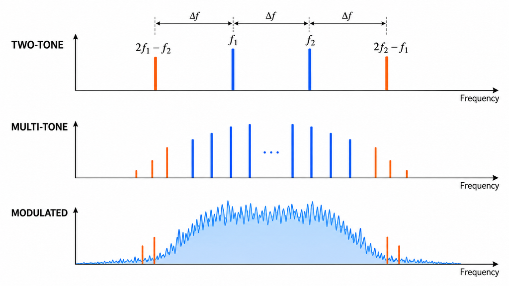
The correct stimulus follows the decision that the result must support. A two-tone test provides a controlled view of device nonlinearity and makes third-order products easy to identify. It proves only the stated carrier pair, spacing, per-tone power, operating point, and measurement method. It does not automatically represent a chain carrying many adjacent carriers or a waveform with different peak statistics.
| Method | Applicable question | Carrier or waveform definition | Power definition | Reference plane and bandwidth | Usable metric | What it cannot prove | Next action |
|---|---|---|---|---|---|---|---|
| Two-tone | How does the DUT behave with one defined carrier pair? | f1, f2, spacing, tone balance, and sweep rule | Per-tone and total Pin/Pout at the stated operating point | PA input and output planes; CW RBW, detector, and usable dynamic range | Absolute or relative IMD products; IMD3; OIP3 only within a valid extrapolation method | Performance with many carriers, a different spacing, or the actual modulated waveform | Use for controlled characterization and repeat at every project-required condition |
| Multi-tone | How does the DUT behave with a defined set of simultaneous carriers? | Complete carrier list, spacing pattern, active combinations, and phase or generation method where material | Per-carrier and total average power, plus the declared drive or back-off rule | Defined PA planes; analysis bandwidth and receiver range covering all wanted and unwanted components | Project-defined product levels, spectral growth, or another agreed multicarrier metric | A waveform whose occupied bandwidth, modulation, or peak statistics differ from the test stimulus | Match the carrier plan to the permitted C-UAS operating state and document the result scope |
| Modulated or wideband signal | Does the PA meet the signal-quality requirement for the actual waveform? | Modulation, occupied bandwidth, peak-to-average power ratio (PAPR) or other relevant statistics, duty behavior, and capture interval | Average and peak quantities with their observation windows and operating-point rule | Defined PA planes; integrated channel, adjacent-channel, notch, or demodulation bandwidth | NPR, ACLR, error vector magnitude (EVM), or another project-defined metric | Direct equivalence to a two-tone IMD3 or OIP3 result without a validated relationship | Use the metric and limit stated by the project acceptance method |
Many contiguous carriers can create combinations that a single carrier pair does not reproduce. Noise power ratio can be useful where a wideband multicarrier stimulus and one or more notches represent the decision, while ACLR or EVM may be the relevant metric for a defined modulation. None of these is a universal replacement for the others. Because equal average watts do not preserve occupied bandwidth, PAPR, or peak behavior, CW and modulated RF amplifier evidence remains comparable only for the quantities and conditions that actually align.
Choose the method in the table, state why it matches the project signal, and record what it cannot establish. If the actual carrier count, modulation, occupied bandwidth, or peak statistics are still unknown, do not upgrade a two-tone result into a system-level conclusion.
6. Decide What the IMD Result Can Support
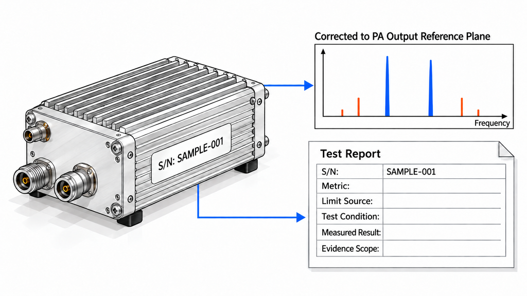
The result needs a metric and a decision rule. An absolute product level in dBm, an IMD value in dBc relative to a defined output tone, IMD3, OIP3, NPR, ACLR, and EVM are not interchangeable. Each one needs its own reference quantity, bandwidth, reference plane, and applicable limit source. A report should also state whether its evidence applies to characterization, a representative sample, a configuration, a batch, or an identified delivered unit.
OIP3 is an extrapolated figure of merit. It can support a controlled linearity comparison when the extrapolation method and operating region are valid, but it does not replace measured product levels near compression or acceptance with the actual waveform. Similarly, a lower displayed product is not automatically a pass if the applicable limit, measurement uncertainty, or decision rule is missing.
Results from different suppliers are comparable only when the metric definition, carrier state, operating point, reference planes, load, thermal condition, method, and evidence scope are sufficiently aligned. If those conditions are only partly aligned, limit the comparison to the aligned dimensions. If a material condition is missing, the correct result is “not comparable yet,” followed by a request for the missing record or a retest under matched conditions—not a supplier ranking.
Evidence scope must remain explicit. If the project requires unit-level delivery acceptance, the buyer should request a record linking one unit and serial number to its dataset, defined test condition, result, and report. A representative or qualification report may still support its stated scope, but it does not establish the result for every delivered unit or an entire batch. The final decision record should name the metric, reference, limit source, applicable scope, conclusion strength, and next action.
RFQ: Define the IMD Test Before Comparing Amplifiers
An RFQ that asks only for “IMD” or “OIP3” leaves the supplier free to choose a stimulus and operating point that may not match the project. Define the test inputs before requesting a comparison:
- List every carrier that can operate simultaneously and identify the permitted combinations.
- State each carrier frequency, the spacing or spacing pattern, and any sweep rule.
- Define the waveform, occupied bandwidth, duty behavior, and relevant peak statistics.
- Specify per-tone or per-carrier Pin, total Pin, per-tone Pout, total Pout, and the applicable average or peak definition.
- Define the PA input, PA output, and receiver reference planes, including the source and sampling-path corrections.
- Record the load, supply condition, cooling arrangement, and required thermal state.
- State the source-combining method and the source-purity evidence required at the PA input.
- Define the receiver method, RBW or integration bandwidth, detector, attenuation, usable dynamic range, and measurement-floor treatment.
- Name the required metric and product order, including the carrier reference used for any dBc result.
- Cite the project limit source, uncertainty treatment, and decision rule.
- Define whether the evidence is for characterization, a sample, a configuration, a batch, or a serial-number-linked delivered unit.
- Require the report to retain the raw observations, corrections, final result, operating state, and evidence scope.
After that record is complete, the RF power amplifier module range can be used for product-family discovery without implying that any listed module already satisfies the IMD requirement. Submit the same bounded test definition through the RF SKYPOWER engineering contact route when a project-specific review is needed. That review can align the product route and evidence request; it is not a guarantee of suitability, a completed test, or an acceptance result.
Conclusion: Treat IMD as a Conditional Linearity Requirement
Treat IMD as a separate C-UAS RF PA requirement when the project explicitly requires a linearity measurement. Without that requirement, trigger the task only when simultaneous components can meet at a common nonlinear node and their products could affect a defined band or system decision. Once either route applies, the result is meaningful only after the carriers, spacing, per-tone and total power, operating point, reference planes, bandwidth, and method are fixed.
This framework can decide whether an IMD task is needed, which stimulus fits the decision, and whether two records are comparable. It cannot define a universal spacing, back-off, product limit, or acceptance threshold, and it cannot turn a two-tone result into proof for a different multicarrier or modulated condition. The most important mistake to avoid is treating every unexpected line as PA-generated IMD—or treating one clean two-tone result as proof that the complete C-UAS chain is linear.
Complete the applicability table, method-definition matrix, and RFQ input checklist first, then close every missing measurement boundary or hold the comparison. Use the resulting record for product-family evaluation and provide the defined carriers, power conditions, waveform, reference planes, method, metric, limit source, and evidence scope for a bounded RF SKYPOWER engineering review.