











Spectral coupling in multi-module RF power amplifier (PA) systems can transfer an adjacent channel’s existing signal or generate new intermodulation (IM) products at a nonlinear junction; similar products may also arise inside the measurement receiver. A line that appears only when two modules operate together is therefore evidence of a state-dependent change, not proof that either module is defective; the channel states, load and measurement reference planes must first be comparable. A reference plane is the defined point in the RF path where a level is measured or specified, such as a PA connector or a coupled sample port.
A useful diagnosis identifies which component changed, where it was observed, and which controlled state or path change supports the next diagnostic step. Without those records, a team can mistake leakage for newly generated intermodulation, blame a module for analyzer mixing, or modify cabinet hardware before identifying a plausible path.
1. What Changes When a Second RF Module Starts Transmitting?
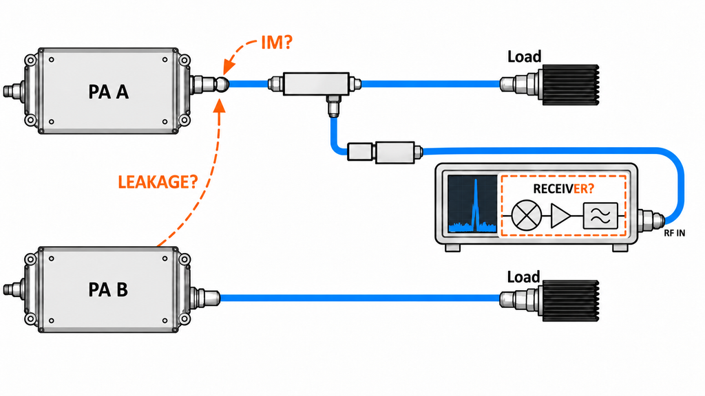
A second active module adds possible coupling paths between transmitters, passive connections, shared references and the measurement chain. It does not make every new spectral component an intermodulation product. Linear leakage transfers energy already present in one channel; by itself, a linear path does not create a new frequency. Intermodulation (IM) is the production of additional frequency components when signals interact in a nonlinear element. That element may be an amplifier output stage or a passive nonlinear contact.
Start by naming the affected channel (the path where the component is observed) and the interfering channel (the adjacent active path suspected of contributing energy). Also name the observation point: for example, a defined PA output reference plane, a coupled sample port, or the analyzer input. The location where a product is observed does not identify where it was generated.
For a narrowband two-tone case, products such as (2f_A-f_B) and (2f_B-f_A) are candidate frequencies to inspect. They are not a root-cause test. Modulated signals may instead produce broadened spectral energy, and a similar component can arise when multiple signals mix in an analyzer or sampling branch. A frequency match narrows what to examine; it does not locate the nonlinear element.
Keep the first conclusion limited: classify the observation as a leakage candidate, a newly generated intermodulation candidate, or a measurement-chain candidate. If the frequency relationship, affected point, channel state or measurement reference plane is unclear, retain the alternatives. Do not infer a failed module, a cabinet isolation value or a universal spacing requirement from simultaneous operation alone.
2. Establish a Comparable Channel-State Baseline
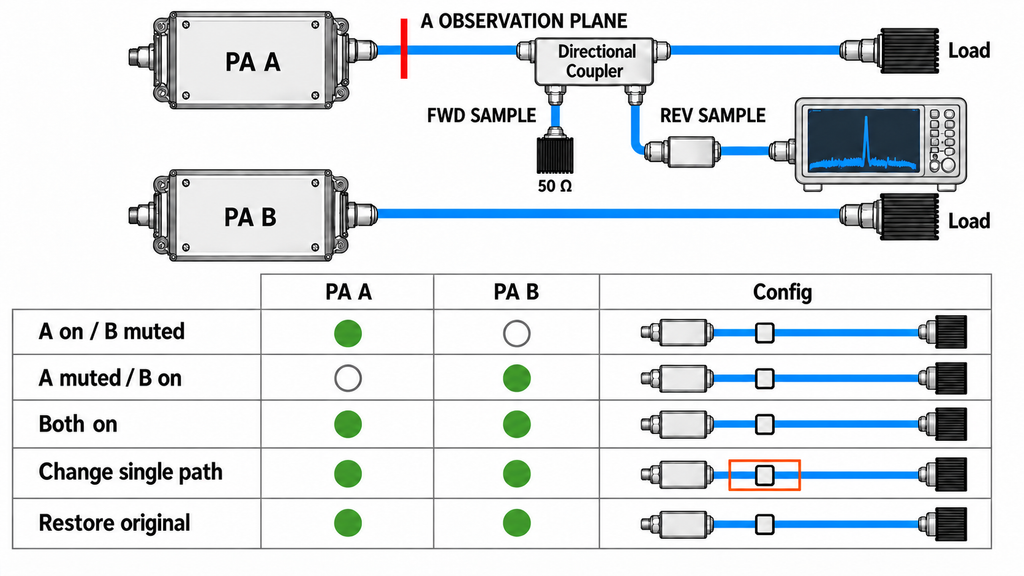
Use a short, repeatable sequence to connect an observed component to channel state. Let A be the affected path and B the adjacent path under investigation. Record the termination and operating state for each row. “RF muted,” “disabled,” “unpowered,” and “replaced by a matched termination” describe different conditions: an inactive port may still reflect or pick up energy. Never disconnect a load while transmitting or directly combine two PA outputs.
| Channel state and termination | Observation point, component and corrected level | Conditions held or single change | Supported conclusion and next action |
|---|---|---|---|
| A operating; B powered with RF muted | Record the point, component or band, and level after the documented path correction | Record A/B frequencies, waveform, drive, load, supply, thermal state and sampling path | Establishes what is visible with B powered but not transmitting; it does not prove B contributes no RF energy |
| A muted; B operating | Record whether B’s existing signal is visible at A’s defined observation point | Keep the sampling topology and analyzer settings identified; record any unavoidable state difference | Supports a direct-leakage observation if B’s existing signal appears at A’s point; it does not show that A+B creates a new product |
| A and B operating in the permitted combination | Record the same observation point and component, including corrected level and analyzer conditions | Compare with the individual states; note changes in total current and thermal state | Shows a combination-related change under the recorded conditions; it does not by itself identify the mixing element |
| One controlled path change | Record the same component before and after the one change | State the path changed and any accompanying load, loss or temperature effect | May support sensitivity to that path if other material conditions remain comparable; otherwise preserve the ambiguity |
| Original path restored | Repeat the original observation and record the same fields | Restore routing, terminations, cover, cooling and analyzer corrections as applicable | A repeatable return strengthens the path association; it still does not establish a component root cause |
A useful record includes each channel’s actual input and output conditions, frequency, waveform and duty cycle, load, PA terminal voltage and current, thermal state, cabinet cover and fan state, source and sampling topology, and synchronization state. Include only values actually observed. Samples must reach the analyzer through rated sampling or attenuation paths; the table is a diagnostic record, not an acceptance limit or a claim that these tests have already been run.
Keep comparisons aligned on the conditions that affect the question. If load, termination, drive, thermal state, correction, or sampling topology changes at the same time, the result has multiple explanations. A change in total current is worth recording when both modules operate, but it does not on its own establish a DC interaction. If a power, thermal or control symptom appears before the spectral change, hand that broader first-change problem to the multi-module fault investigation. For a controlled baseline, distinguish what a matched dummy-load baseline can establish from checks of the real RF path; these checks address distinct measurement boundaries.
3. Exclude Mixing in the Measurement Receiver
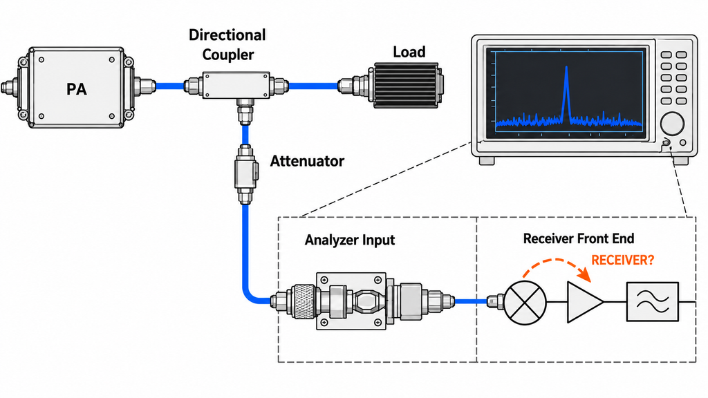
An analyzer marker shows the level at one displayed frequency; it does not describe the total signal burden at the analyzer front end. Multiple strong signals can interact in an analyzer, preamplifier or combined sampling branch. The displayed product can reflect contributions from both the device under test (DUT) and the receiver, and those contributions may add or partially cancel.
A controlled change in analyzer input attenuation, or an appropriate external attenuator or preselector, can help assess receiver contribution while the DUT state stays stable. Apply frequency-dependent corrections to the observed levels. More attenuation also raises the input-referred noise floor, so a line that disappears may have become unresolvable rather than absent. Check the total input level, analyzer operating range, branch isolation, unused-port terminations, correction and noise floor before drawing a conclusion.
The response to an attenuation change is architecture-, frequency- and phase-dependent. One reading, one slope, or one setting is not a universal discriminator between DUT and analyzer products. If the input safety margin, linear range or ability to resolve the component is unknown, leave the source unresolved. A stable, separate sampling path can help identify whether signals meet only inside a combiner; it does not prove the rest of the cabinet is free of coupling. Compare a source or single-PA spur with the A+B observation at the same reference plane before attributing it to multi-module interaction; the single-module spurious-output isolation method covers the source/PA side of that comparison.
4. Trace the Coupling Path Before Changing the Cabinet
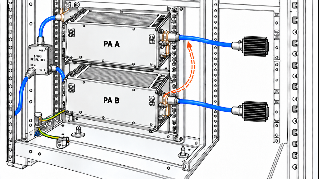
Once the component and channel states are recorded, vary one plausible path at a time. A path comparison is informative only when the channel combination remains permitted and stable, the loads and terminations are defined, and the measurement point and correction remain known. If a change also alters load, insertion loss, drive or thermal state, record that effect; it weakens a simple path attribution.
| Candidate path | Controlled comparison or evidence | What the result may support | What it cannot prove | Next specialist |
|---|---|---|---|---|
| Output or shared passive path | Compare separately defined, rated and terminated paths with documented loss and reference points; preserve the permitted channel state | A repeatable component change may support sensitivity to an output or passive path | It does not identify a particular connector, amplifier stage or failed component | Review the relevant RF routing or passive network |
| Space or cable path | Make one controlled change to cable route, separation or temporary screening; observe the same component at the same point | A repeatable change may support spatial or cable-path sensitivity | A probe reading or temporary improvement does not establish the exact coupling mechanism or a required distance | RF PA shielding seams, penetrations and cable-entry EMI |
| Shared supply or reference path | Compare a controlled branch/reference condition and record PA-terminal voltage, ripple or common-mode evidence alongside the spectrum | Correlated, repeatable changes may support a shared supply or reference path for further review | Stable telemetry alone does not rule out RF coupling or establish a DC root cause | If evidence points to a return or signal reference, review RF PA grounding, DC return and signal reference; assess shared DC bus interaction only when that branch is indicated |
| Measurement or sampling path | Compare independent samples with a controlled combined sampling branch, identified isolation and rated terminations; track analyzer settings and noise floor | A change confined to the measurement branch may support receiver or combiner contribution | It does not show that no cabinet-level coupling exists | Review the analyzer/sampling setup; if the physical route identity remains unclear, verify cabinet RF routing identity and performance |
Board-level supply or return measurements from another device are a mechanism clue, not evidence for this cabinet. A nonlinear connection may generate passive intermodulation (PIM), while a reverse signal at a nonlinear PA output stage may generate transmitter IM. These mechanisms guide the path test; use the table’s next-specialist route only when its row supports it. A temporary screen, cable move or nearby probe can show path sensitivity, but it does not replace controlled measurement.
Do not remove protective earth or test a high-power output open-circuit. If several variables changed, the component is near the measurement floor, or the same change cannot be repeated, report the path as unresolved and list the alternative explanations. A path association is useful because it assigns the next investigation; it is not a root-cause verdict.
5. Define Isolation Evidence and Repeat the Spectral Test
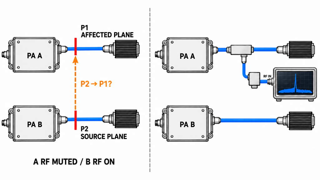
“Isolation” describes transfer between a specified pair of ports under stated conditions; it needs a direction, frequency or bandwidth, termination, channel state and reference plane. A branch-to-branch isolation measurement, a PA’s small-signal reverse gain, cabinet channel-to-channel isolation and a spectrum measurement with the multi-module system operating in its defined configuration answer different questions. In particular, small-signal reverse gain does not establish running spectral isolation, and none of these measures alone proves that the final combination meets a project requirement.
For a linear path, define P2 as the source-side power and P1 as the coupled power at the affected-port reference plane. Use corrected power values in the same linear units at their stated reference planes, not dBm values. 10 log10(P1/P2) is the transfer ratio in decibels; a passive lossy path gives a negative value, while 10 log10(P2/P1) reports the corresponding positive isolation loss. State the terminations and reference planes with the ratio. This estimate describes linear leakage only; it does not predict nonlinear intermodulation. Do not substitute a calculated estimate, a small-signal S-parameter result, or a temporary probe observation for a spectrum measurement in the operating configuration.
The project team should define the unwanted-component limit, interfering-channel state, measurement point, available dynamic range and uncertainty, and the applicable requirement that supplies the limit. Any applicable isolation value, cable spacing, distance or spurious-emission limit must come from the project requirement; none is universal. If the project limit is missing, the measurement is near the system’s resolution capability, or the required reference plane is not defined, keep the decision open rather than label the result acceptable.
After a path change, restore the intended final routing, cables, cabinet covers, cooling, terminations and corrections, then repeat the spectrum test with the original and permitted maximum channel combinations as applicable. A temporary arrangement may help identify a path; only evidence from the defined final configuration can address that configuration’s spectral behavior. Only if project evidence and its requirements justify considering a passive device does the isolator or circulator evaluation become a separate design question; it is not a universal fix for an unexplained component.
RFQ: Request a Multi-Module Spectral Review
Before requesting an engineering review, assemble the information needed to reproduce the observation. These are buyer-supplied inputs, not existing RF SKYPOWER test records or a promise that a particular module will be suitable.
- Permitted channel combination and whether each channel is active, RF-muted or otherwise terminated.
- Module model, configuration and serial number for each participating unit.
- Source setting and actual input at the defined reference plane.
- Output target and its reference plane.
- Spectrum files, component or band of interest, correction method and analyzer or sampling settings.
- Load and any isolation network, including its stated port pair and relevant termination.
- The controlled change and the before/after observations, including any accompanying change in load, loss or thermal state.
- DC and thermal observations, including PA-terminal voltage/current where available and the operating state.
- Explanations or paths that remain unresolved.
Submit the reproducible channel-state and spectral record to RF SKYPOWER for a light engineering review of the likely coupling path and next measurement boundary. The request does not imply that RF SKYPOWER has tested this configuration, can diagnose or resolve it from incomplete records, guarantees a result, or recommends a specific model. Module selection depends on the recorded frequency coverage, output target and integration constraints; project-specific evidence must confirm suitability, and the RF power amplifier modules family provides a starting point for product discovery.
Conclusion: Assign the Path Before Rejecting a Module
Multi-module operation can introduce additional paths: linear leakage transfers an existing signal, nonlinear interaction may generate new intermodulation products, and the measurement receiver may create similar products. A limited path judgment requires comparable channel states, defined terminations and reference planes, a controlled assessment of receiver contribution, and enough measurement range to resolve the component. The path framework does not define a project’s isolation or unwanted-component limit or determine model suitability; those decisions require applicable project requirements and product evidence.
A line that appears only in the combined state does not prove that a module is faulty. A single-module pass or small-signal isolation value does not replace a spectrum measurement in the final combination. The next engineering action is to track the same component through comparable states and one controlled path change, preserve any alternative explanation, assign the supported path to its specialist review, and repeat the test after restoring the final configuration. Once project limits and applicable product evidence are defined, bring that record to the same light engineering review requested in the RFQ.