










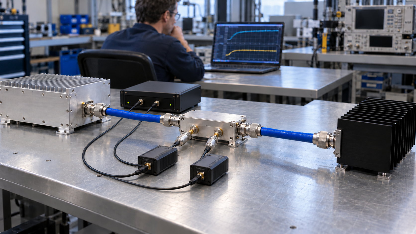
External forward-power (FWD) and reflected-power (REV) measurements can challenge a suspected false VSWR alarm only when they represent the condition the RF power amplifier actually evaluated. Compare the PA’s revision-specific alarm metric with calibrated external evidence from the relevant event, using a defensible RF reference plane, operating state, time window, and uncertainty decision rule. A normal reading recorded after foldback or shutdown cannot rule out the earlier trigger.
First identify what the internal alarm monitors and which event the external record covers. If the trigger definition, reference-plane relationship, or necessary event evidence is missing, the finding is not comparable yet.
1. What Does a “VSWR Alarm” Actually Mean Inside the RF PA?
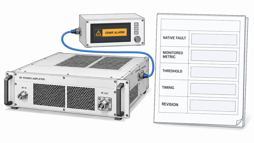
When assessing RF power amplifier load mismatch protection, the controller’s “VSWR alarm” label does not by itself identify the quantity that triggered the response. Depending on the module and its hardware, firmware, and configuration revision, the monitored condition may be an absolute REV-power limit, a calculated FWD/REV ratio, a detector-voltage threshold, or a controller-derived state. The displayed alarm may also be latched after the RF condition has cleared.
Start with the applicable alarm definition for the specific PA and revision. Identify the native fault code, the sensing source, the monitored quantity and units, the configured threshold, and the action associated with that threshold. A warning, output foldback, and shutdown are different states. RF power amplifier alarm monitoring must trace a generic cabinet alarm to the originating PA and its native fault before that alarm can be used as evidence.
For a ratio-based VSWR decision, establish the manufacturer’s minimum valid FWD level and the detector’s usable range. Once FWD falls near the measurement floor, a REV/FWD ratio can become unreliable even if both reported values appear plausible. Also identify any persistence period, debounce, hysteresis, fault latch, and reset rule. An external instantaneous reading cannot be compared directly with an internal alarm that requires a condition to persist for a defined interval.
Keep the version-specific trigger definition with the event record. Where a threshold file governs acceptance, verify its revision, applicability, and test conditions using the RF PA alarm-threshold file guidance.
2. How Can an External FWD/REV Measurement Be Trusted?
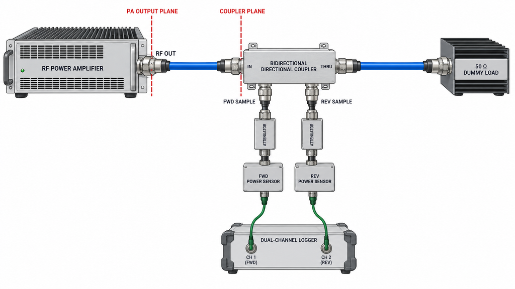
The external measurement chain must be characterized before its readings can test an internal alarm. In a controlled setup, an appropriately rated bidirectional coupler, or another verified directional arrangement, is placed between the PA output and the approved load. Its forward and reverse sample paths feed suitably attenuated measurement channels. Use or terminate coupled ports as the coupler specification requires. Rate the RF components, load, attenuation, and sensor inputs for the applicable forward and reflected power, including permitted mismatch conditions. Do not introduce an uncontrolled open or short circuit to provoke an alarm.
Record coupler orientation, frequency-dependent coupling factors, directivity, calibration status, instrument ranges, sample-path attenuation, and cable or adapter losses. Coupling-factor and attenuation corrections account for known gain or loss; they do not necessarily remove finite-directivity leakage from FWD into the REV channel. That leakage depends in part on relative phase and can dominate a small REV reading. Unless a validated vector correction is available, retain its effect in the uncertainty budget rather than presenting it as fully corrected away.
Preserve the raw FWD and REV readings before applying channel-specific corrections at the actual coupler measurement plane. An external reading used to assess RF power amplifier output VSWR cannot be assigned to the PA output connector or internal sensing plane without a characterized relationship between the reference planes. A scalar insertion-loss adjustment may be adequate only where fixture mismatch and multiple-reflection effects are demonstrably negligible within the required uncertainty. Otherwise, apply a validated reference-plane method supported by the necessary measurement information. Complex wave data may be needed for vector de-embedding; a fixture S-parameter file alone does not turn scalar FWD/REV readings into a valid PA-plane result. When the evidence is insufficient, leave the result at its measured plane and classify the internal–external comparison as not comparable yet.
Adding a coupler or adapter may also change the impedance presented to the PA. Preserve the original RF-path configuration, identify each added component, and state whether the alarm recurred in the instrumented configuration. A clean reading from a modified path does not retrospectively invalidate an alarm in the earlier installation. The FWD/REV reflected-power logging guide covers the detailed measurement corrections and record requirements.
3. Are the Internal Alarm Threshold and External VSWR Evidence Comparable?
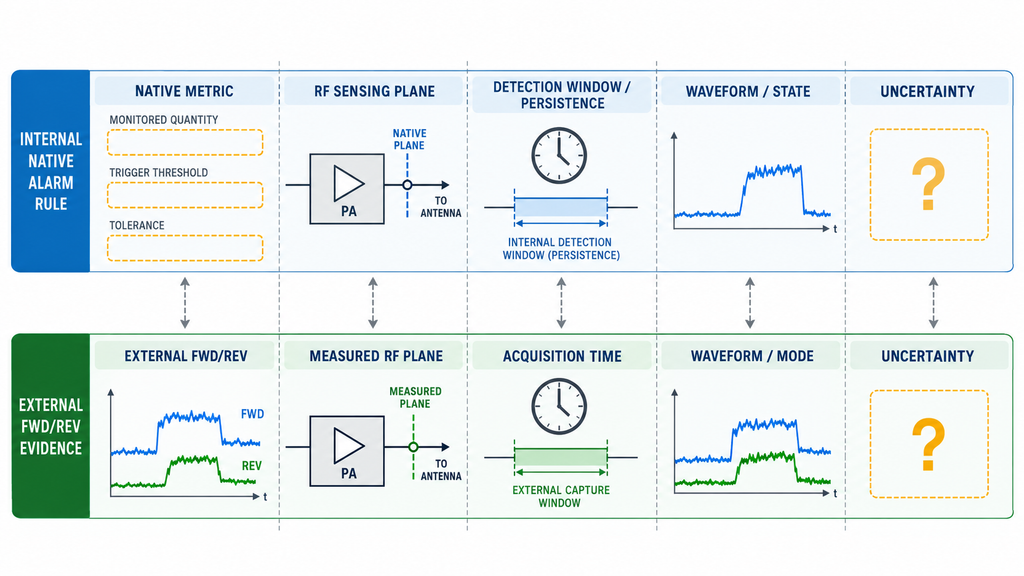
Compare the metric the PA actually monitors. If protection uses an absolute REV-power threshold, an externally calculated VSWR alone cannot establish whether that threshold was crossed; corrected event-time REV evidence is needed, with FWD and operating-state evidence where the rule requires them. If protection uses a VSWR ratio, the external ratio must be valid at the relevant FWD level, frequency, waveform, and detection interval. A detector-voltage or controller-derived trigger additionally requires the documented mapping from external RF quantities to that native decision.
For a suitable single-frequency measurement with valid directional powers expressed in linear units at the same reference plane, the reflection-coefficient magnitude is |Γ| = sqrt(P_REV / P_FWD), and VSWR = (1 + |Γ|) / (1 – |Γ|), provided P_FWD > 0 and the physical power ratio is below one. Do not divide dBm values to calculate the ratio. For pulsed, modulated, or multi-frequency operation, establish that the external measurement bandwidth, detector mode, and averaging interval represent the quantity that the PA used for protection; a band-integrated average need not describe a short peak or a unique single-frequency VSWR.
Define the comparison decision rule before interpreting a difference. For a documented one-sided REV threshold, a credible contradiction requires the upper uncertainty limit of external REV to remain below the lowest permissible internal trigger level throughout the relevant detection window. Affirmative external support requires the lower uncertainty limit to exceed the highest permissible trigger level for the required persistence interval. These conservative bounds apply only when the actual native rule, detector response, reference-plane relationship, and event capture make that comparison valid. Evidence that merely does not exclude a trigger is not independent support for one.
If the measurements are otherwise comparable but their uncertainty bounds overlap the permitted trigger region, the outcome is comparable but inconclusive. Missing native thresholds, event timing, or other eligibility conditions instead produce not comparable yet. For ratio-based rules, include FWD validity and uncertainty propagated through the ratio. No universal VSWR threshold or uncertainty guard band can be inferred from these examples.
Account for uncertainty on both sides: external sensor calibration, finite directivity, sampling mode, fixture mismatch and justified reference-plane translation; internal detector scaling, threshold tolerance, filtering, and timing. State whether an uncertainty interval is a specified limit or a statistical estimate, with its coverage basis, factor or probability and any predeclared guard band where applicable. Include shared or correlated contributions to FWD and REV uncertainty rather than automatically treating the two channels as independent. Align the internal detection window with both external channels, including clock uncertainty and sampling delay. A difference larger than one instrument’s stated power accuracy is not enough to reject the internal alarm.
Internal–External Alarm Evidence Alignment Record
| Evidence field | Record and comparison requirement |
|---|---|
| Internal alarm code | Native PA fault identity and whether the reported status is native or controller-derived |
| Monitored quantity | Absolute REV, calculated VSWR, detector voltage, or another revision-defined quantity; include units and minimum-valid-FWD rule where applicable |
| Threshold and configuration revision | Applicable setpoint, tolerance, persistence/debounce, hysteresis and latch semantics, with hardware/firmware or threshold-file revision |
| Internal FWD/REV indication | Available detector or telemetry values, source, units, scaling, state and timestamp; mark unavailable rather than inferring them |
| External raw FWD/REV | Uncorrected directional-channel readings, units, peak/average mode, sensor bandwidth or averaging aperture, time window, and channel alignment |
| External corrected FWD/REV | Linear power values after justified coupling and attenuation corrections, derived VSWR where valid, and residual directional uncertainty; retain the raw readings |
| RF reference plane | Actual external measurement plane and documented basis for relating it to the internal sensing plane; state any uncharacterized fixture mismatch |
| Frequency | Actual event frequency or verified frequency interval covered by the measurements |
| Waveform and operating state | Drive/output state, CW or modulated duty condition, load configuration and relevant thermal state |
| Alarm event time | Native assertion time, clock source, resolution and alignment to the external acquisition window; state known or unknown reporting delay |
| Coupler and sensor calibration | Instrument identities, applicable calibration validity, coupler orientation, coupling factors, directivity and sensor response mode |
| Correction factors | Frequency- and direction-specific sample-path corrections; distinguish scalar loss adjustments from validated fixture or reference-plane de-embedding |
| Measurement uncertainty | Residual directivity leakage, sensor uncertainty, fixture mismatch, correlated FWD/REV terms, internal detector/threshold tolerances, bandwidth and time-base uncertainty; state interval basis or unknowns |
| Comparison eligibility | First mark whether metric, plane, waveform, event capture and internal rule are comparable; then separately record independently supported, credible conflict or comparable but inconclusive after uncertainty is applied |
| Missing evidence | Specific documents, calibration records, internal timing data or waveform capture needed before a credibility conclusion |
Use this record to establish whether a comparison is eligible before assigning a decision. External measurements cannot supply an internal threshold that the manufacturer’s applicable documents do not define.
4. Could a Transient Trigger an Alarm That the External Meter Missed?
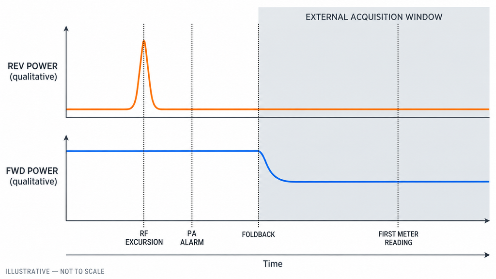
Yes. The PA may detect a brief reverse-power excursion, assert a fault, and reduce or remove RF output before a hand-held meter or slow controller log updates. The first subsequent reading then describes the protected operating state, not the original triggering interval.
Establish a shared event timeline with four points: internal alarm assertion, external acquisition window, RF foldback or shutdown, and first post-protection reading. An RF trigger can precede the recorded alarm assertion because of detector integration, controller processing, communications, or latching. Account for the applicable look-back interval and known reporting latency; a trace beginning exactly at the reported assertion time may miss the cause. If those delays cannot be established, report that limit rather than assuming full coverage. Record each clock source and its resolution instead of assuming synchronized timestamps.
Time coverage also depends on instrument response. Check sensor video bandwidth, detection and peak/average mode, integration or averaging aperture, acquisition trigger, and FWD/REV interchannel timing. A dense log of heavily averaged readings may miss a short excursion even when its timestamps span the alarm. Compare these capture characteristics with the documented internal detector response where available.
Assign one of three coverage findings. Captured means the FWD/REV channels are time-aligned and their verified response and acquisition window can resolve the relevant pre-trigger condition. Partially captured means a timing, bandwidth, averaging, or channel-alignment limitation leaves a material gap. Unavailable means the relevant RF interval was not observed or the record cannot be correlated with the native alarm.
Captured clears the event-coverage requirement only; the metric, reference-plane, operating-state and uncertainty conditions described above must still pass before a credible conflict can be reported. A partial or unavailable capture may justify an approved instrumented retest but cannot establish a false alarm. If the fault reaches the operator through a cabinet controller, the RF PA status-feedback mapping guide helps distinguish the displayed timestamp or label from native PA feedback.
5. What Do Matching and Conflicting Measurements Actually Prove?
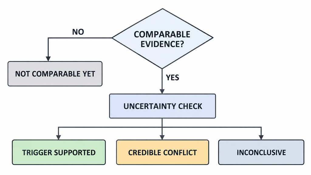
Qualified event-time evidence independently supports a trigger only when it meets the documented condition under the stated timing and uncertainty decision rule. Measurements that merely fail to rule out an excursion are not affirmative evidence that it occurred. A conflict is credible when the external record could have captured the trigger, the internal rule applies to the same RF condition, and the applicable uncertainty bounds exclude that trigger.
Alarm Credibility Decision Matrix
| Internal–external pattern | Internal trigger evidence | External FWD/REV evidence | Comparison condition | Supported decision | Next action |
|---|---|---|---|---|---|
| Trigger supported | Native monitored quantity, threshold range, persistence and response timing are defined | Qualified event-time readings independently meet the documented trigger condition under the declared uncertainty decision rule | Same event, justified plane and FWD range, adequate capture, correct waveform and required persistence | Trigger is independently supported for the measured event; physical root cause remains open | Retain the record and investigate the installed RF path separately if needed |
| Credible conflict | Native trigger and threshold tolerance, detector response, and controller mapping are defined | Qualified event-time readings and their uncertainty bounds exclude the documented trigger condition | Metric, plane, waveform, persistence interval and capture response are demonstrably comparable | An internal sensing, configuration or reporting discrepancy merits engineering review; a false alarm is not yet proven | Review detector calibration, threshold application and controller mapping |
| Essential conditions missing | Metric, revision, threshold tolerance or timing rule is incomplete | Readings exist but reference-plane, bandwidth or uncertainty requirements may be unresolved | Not comparable yet: essential comparison conditions have not been established | No defensible finding on alarm credibility | Name and obtain the missing evidence before interpretation or retest |
| Post-protection reading only | Alarm is recorded, but the preceding RF condition is not | Normal readings begin after foldback, mute or shutdown | Pre-trigger interval unobserved | Earlier trigger remains unverified; recovery data cannot disprove it | Capture the trigger window during an authorized retest |
Swipe horizontally to compare all six decision fields →
Comparable but inconclusive remains a distinct decision when all prerequisites pass but the uncertainty interval overlaps the permitted trigger region. Record it in the Alignment Record; it neither independently supports nor excludes the trigger. Reserve not comparable yet for missing prerequisites, and obtain stronger event evidence before reaching a firmer conclusion.
Consider an illustrative post-trip reading of 100 W FWD and 4 W REV at one valid reference plane. The calculated VSWR is 1.50:1, but that number cannot overrule an earlier alarm if the instrument began recording only after output reduction. A well-supported discrepancy instead warrants a review of sensing or alarm logic without disabling protection.
If qualified event evidence supports a real mismatch, use the post-installation reflected-power alarm diagnosis to examine the installed RF path and PA-side conditions. That physical-path investigation is separate from deciding whether the original alarm was supported by adequate evidence.
6. What Evidence Should Be Saved Before Retest or Engineering Escalation?
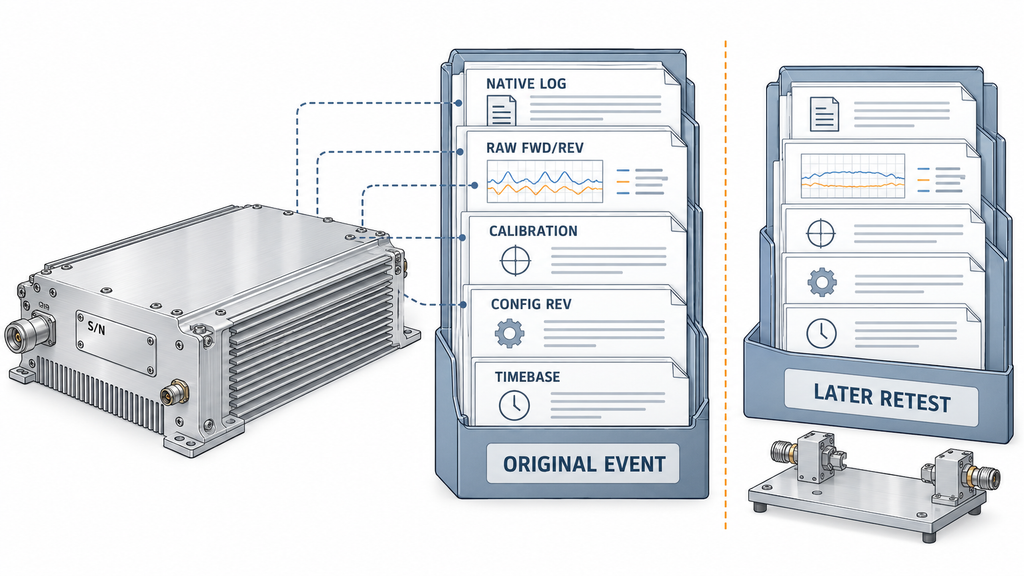
Preserve the original event before changing the load, connector stack, RF source, monitoring settings, or PA configuration. The alignment record should retain raw and corrected RF measurements, their limitations, and the comparison decision. Attach the PA model and serial number, applicable hardware and firmware revisions, threshold-file version, controller/channel mapping, and original time-stamped status log where available; record any missing native log or clock reference explicitly. Record module-terminal DC conditions and the original RF-path configuration where they affect interpretation. Label each later retest as a separate event.
State the unresolved engineering question directly: whether the documented internal trigger condition occurred within a measurement interval capable of observing it, or which missing evidence prevents that finding. Document any coupler or fixture added for a retest so its measurements are not merged with an earlier uninstrumented event. Never force an uncontrolled mismatch or defeat protection for a more decisive screenshot; reproduce conditions only within the approved module and load limits.
Where unit-level acceptance applies, bind the findings to that unit’s S/N and applicable report. Traceability alone does not establish acceptance of the module or installed system. For controlled testing of triggering, foldback, shutdown and recovery, use the RF PA protection-logic validation guide rather than treating this evidence comparison as an acceptance procedure.
Conclusion
Calibrated external FWD/REV evidence can support a VSWR-alarm trigger, reveal a discrepancy requiring sensing or reporting review, or leave the alarm unassessable. A credible conclusion depends on the documented native trigger rule, a justified common RF measurement basis, sufficient event capture and an uncertainty decision rule. External disagreement alone does not prove an internal error or establish a model-specific VSWR limit.
Preserve the original alarm record before retesting. If the relevant RF interval was missed, state that limitation. If the record is comparable but uncertainty still overlaps the trigger condition, report an inconclusive result. Obtain missing threshold, fixture, calibration or timing evidence before assigning fault to the PA, controller or installed RF path.
For model-specific engineering review, provide the PA model and S/N, hardware/firmware and threshold revisions, event frequency, waveform and operating state, load and coupler configuration, measurement and internal sensing planes, raw and corrected FWD/REV data, acquisition settings, event timeline and unresolved discrepancy to the RF SKYPOWER engineering team. For a separate amplifier-selection task, use the RF power amplifier module range.