










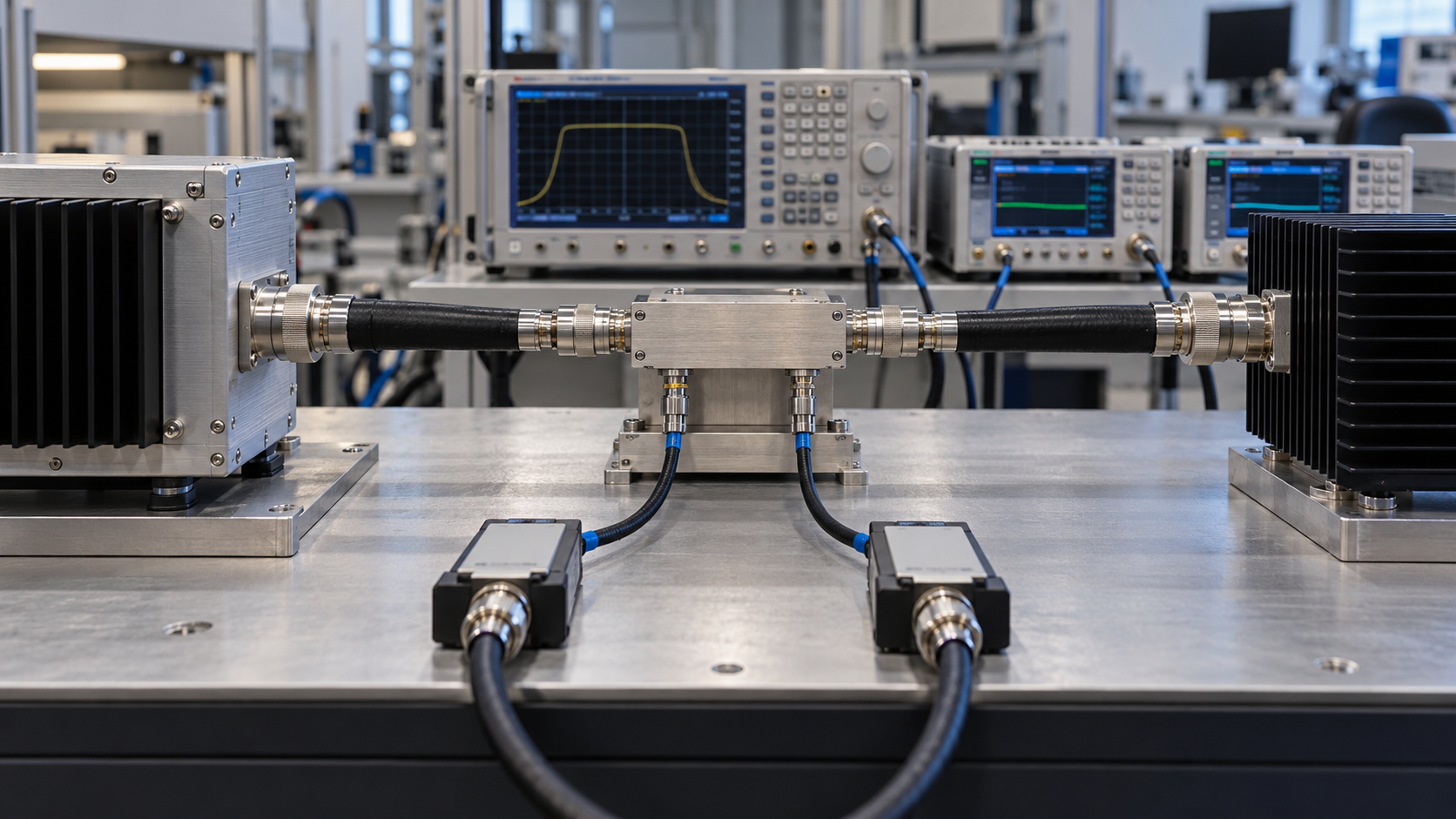
Directional coupler orientation in RF power amplifier testing determines whether an instrument channel samples a wave traveling from the PA toward the load or the reverse wave. A swapped physical path or channel map can make a reading appear abnormal, so define forward at the actual coupler plane from the PA/source side toward the actual load and confirm that direction against the exact model’s port diagram.
The display label alone cannot establish which physical branch the instrument measured. If the branch, sensor, channel name, or existing correction assignment is unclear, retain the result as a configuration question before attributing it to the PA or load. Direction mapping can make a reading interpretable; it does not establish calibration, measurement accuracy, or PA acceptance.
1. Define Forward at the Coupler Reference Plane
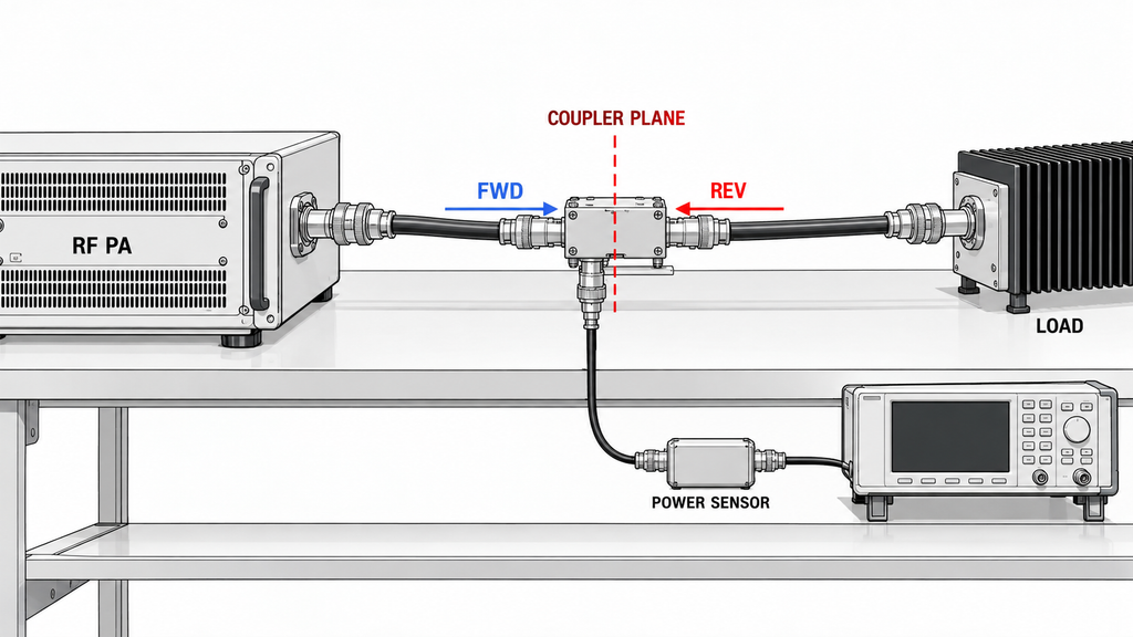
For this test setup, forward means the traveling wave moving along the mainline from the PA side toward the actual load. Reverse means the wave traveling back from the load toward the PA. Both directions are defined at the coupler’s stated measurement plane and along the physical mainline; a software label such as FWD or REV does not define that plane or prove the connection.
A coupled-port sensor reads a sampled signal, not the full mainline power and not the net power absorbed by the load. Keep the raw reading at the sensor separate from any value represented at another plane. An existing correction may represent a downstream or upstream plane. Record the physical sample branch and channel to which it is assigned; its calculation and validation remain separate from the direction map.
A direction label only has meaning at the test’s defined plane and operating condition, so identify both before interpreting the sampled wave during RF power amplifier testing.
2. Match the Port Diagram to the Physical Setup
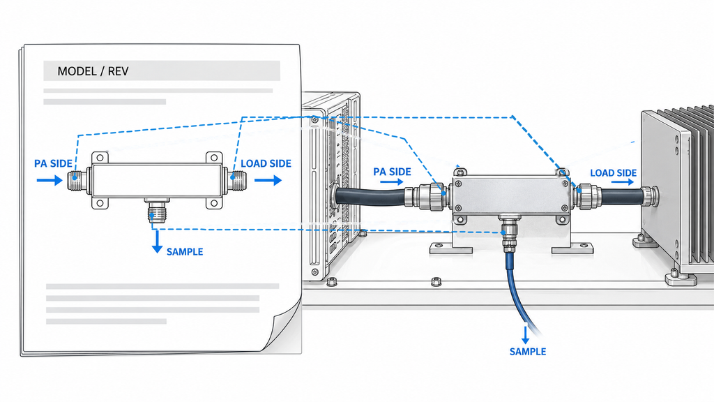
Start with the directional coupler’s exact model and revision. Use its manufacturer diagram to identify the mainline ports, accessible sample ports, any internal termination, and any externally accessible auxiliary port. Connector count, case orientation, port number, or an arrow on another model cannot establish the meaning of this unit’s connections.
A three-port design may expose one coupled branch while internally terminating another port. A bidirectional design may expose samples for both directions, while a dual-directional arrangement can use separate coupled paths. Those descriptions distinguish architectures; they do not create a universal connector-to-FWD rule. The diagram for the actual model must show how its sampling direction relates to the intended mainline direction. Mainline and sample ports also have different roles and may have different power limits, so do not interchange them based on appearance.
Trace the mainline from the PA/source-side connector through the coupler to the actual load-side connector. If the load is beyond a cable, transition, filter, or other component, identify that physical load path rather than treating the nearest connector as the load. Terminate an unused accessible port only as the applicable device documentation requires.
Direction and branch mapping record
| Connection item | Confirm in manufacturer documentation | Trace in the physical setup | Record / status |
|---|---|---|---|
| Coupler identity and direction reference | Exact model, revision, port diagram, arrow convention, and documented port roles | Match the documented unit to the installed coupler and identify its position on the mainline | Record model/revision and diagram source; state the physical coupler plane used for the reported value |
| PA/source-side mainline | Which documented mainline port is the source-side connection | Follow the cable from the PA/source to the coupler | Record the actual connector and source-side path |
| Load-side mainline | Which mainline port continues toward the load | Follow the path from the coupler to the actual load, including intervening hardware | Record the actual connector and load endpoint |
| Forward sample branch | Which accessible sample port represents the forward wave for this orientation | Follow that port’s cable to its sensor and instrument input | Record the port-to-branch trace; do not infer a universal port number |
| Reverse sample branch or no accessible port | Which port represents reverse sampling, or whether this structure exposes no such port | Trace the available branch, if present, to its sensor and instrument input | Record the actual reverse path or “no accessible reverse sample port” |
| Sensor, channel, and correction identity | Sample-port function, instrument input/sensor limits, and the instrument’s correction-setting definitions | Follow each sample cable through the sensor to the instrument input and software channel | Record the actual sensor, channel name, and existing correction identifier; do not validate its numerical value here |
| Unused auxiliary port | Whether the port is internally terminated or requires an external termination and under what conditions | Identify the port and its actual termination | Record the observed configuration and document reference |
The entries are prompts for the reader to verify against the actual unit and setup, not measured results. If the model/revision or port role cannot be matched to the hardware, stop using the case orientation or label as a substitute for the manufacturer definition.
3. Trace Each Sample Port to Its FWD or REV Channel
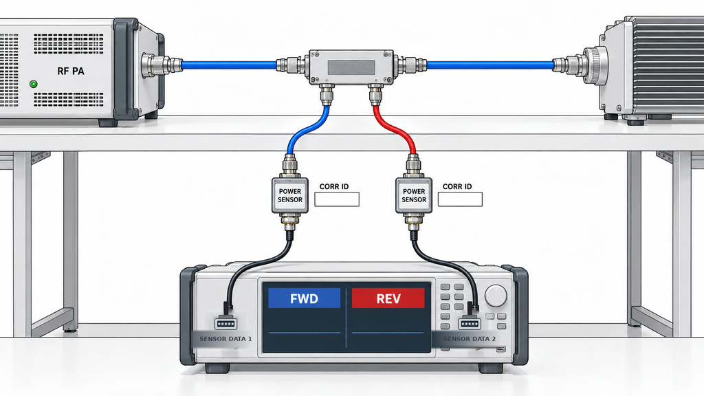
Follow each accessible sample path continuously: coupler port, sample cable, sensor, instrument input, software channel name, and the identifier of any existing correction configuration. Record what is physically connected and what the instrument calls that channel. A channel named “FWD” is only a label until its sensor and cable are traced back to the manufacturer-defined sample port and the forward direction set in Section 1.
Keep the existing correction identifier attached to the sensor and physical branch it was configured for; changing a display name does not transfer that correction to another path. If a value is represented at another plane, it depends on the applicable test-path loss compensation; this mapping records the existing assignment but does not calculate or validate the correction, recalculate Pout, or assess sensor calibration. Calibration status belongs to the identified instrument and sensor; power-meter calibration evidence cannot show which physical sample branch reached an input.
If the instrument has only one accessible sample direction, record that limitation rather than filling in an assumed reverse channel. If two channels are available, trace both independently. Do not swap plotted values or rename channels to make the display look consistent while leaving the source path, sensor identity, or existing correction assignment unresolved.
4. Verify Direction with a Controlled Low-Power Check
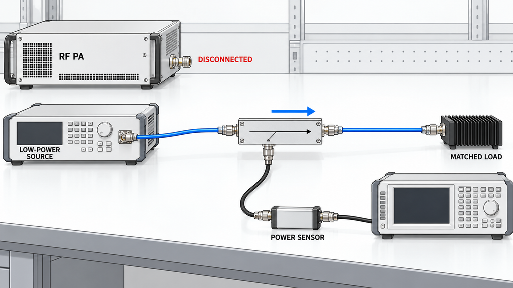
When the port diagram and physical labels do not make the mapping unambiguous, use a direction check only under a method permitted by the coupler and instrument documentation. First turn RF off and physically disconnect the PA from the coupler. Keep it disconnected throughout the check. A qualified test engineer can then use an approved low-power source on the permitted source-side mainline port, with an appropriate matched termination on the opposite mainline end and the sample branches terminated or connected with the required instrument protection. The allowed frequency, power, terminations, and receiver limits must come from the actual equipment procedure; there is no universal test level or pass ratio for this article.
Compare the response pattern with the exact model’s documented coupled and isolated directions for that injection, then record the frequency, injection direction, raw responses on the available channels, actual port/cable path, and manufacturer diagram. Finite directivity can allow a response on an isolated branch; the check asks whether the observed pattern is explainable under the applicable method, not whether the opposite channel reads zero. If the hardware exposes a reverse sample, a second injection from the actual load-side mainline port may be used only when the device procedure permits it; switch RF off before changing connections, move the approved matched termination to the PA-side mainline port, and keep the PA disconnected. If no suitable reverse channel exists, record that the check confirms only the accessible direction. A screen label or a smaller REV display is not a substitute for this observation.
Stop if the PA is not fully disconnected, the permitted input port or limits are unknown, the required termination is unavailable, or the observed response cannot be reconciled with the model-specific diagram. Resolve the setup or request the missing device information before using the readings to diagnose the PA or load. This is a configuration check, not a coupler calibration, directivity specification test, full-power test, or PA acceptance test.
5. Separate Orientation Errors from Directivity Limits
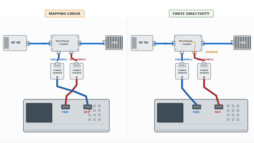
A verified port map answers which physical direction a channel is intended to sample. It does not guarantee that the sampled reverse reading is free of forward-signal leakage. Finite directivity, imperfect port terminations, frequency, and the measurement system’s usable range can affect how well the two traveling waves remain separated. A small reverse display can therefore be consistent with the setup’s limits as well as with a low reflected signal; it is not a universal proof that orientation or load match is correct.
| Observation | Why it needs checking | Next check | What you cannot conclude |
|---|---|---|---|
| Mainline, sample cable, or channel labels appear crossed | The physical path may not match the documented direction or display name | Trace each connector and cable to the actual load, sensor, and instrument input against the exact model diagram | You cannot assign FWD/REV meaning from the display label alone |
| The reverse channel shows a very small or unclear response | The channel may be absent, below a usable response range, affected by directivity/leakage, or mapped to another path | Confirm the device structure, accessible port, termination, instrument path, and applicable measurement range | You cannot treat “near zero REV” as a universal pass threshold or proof of a matched load |
| Direction mapping agrees with the diagram but the PA reading remains abnormal | The remaining cause may lie in the measurement path, load, operating condition, or PA; the mapping check does not isolate it | Preserve the verified map and use the applicable test or troubleshooting method for the remaining question | You cannot identify a root cause or declare the PA failed from this observation alone |
A reverse value near the setup’s effective measurement limit needs an RF PA measurement uncertainty assessment tied to the characterized system and test conditions before it can support a quantitative decision. Direction mapping alone supplies no directivity, return-loss or acceptance threshold.
6. Preserve the Direction Map Before Comparing PA Results
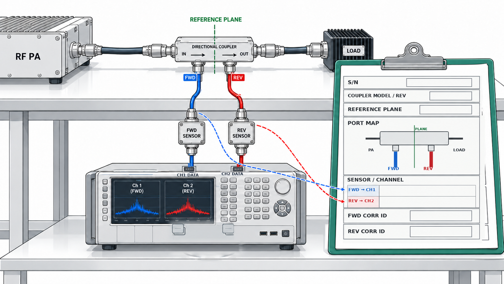
Before changing a connection, preserve enough information to reconstruct the old mapping: coupler model and revision, the diagram reference, the PA/source-side and actual load-side mainline paths, each accessible sample port and cable, sensor identity, instrument input and software label, the identifier of the existing correction configuration, stated measurement plane, check frequency, injection direction, and observed raw channel response. Keep original records and images; a later change of channel name does not establish what an earlier measurement represented.
For project-required unit-level evidence, tie the direction map, readings and test conditions to the tested PA’s identity/S/N, test time, dataset and report; define that evidence scope in the RFQ or acceptance plan.
If the original port-to-channel relationship can be reconstructed, any correction to labels or records must remain traceable to the original configuration and follow the approved method. If it cannot be reconstructed, mark the affected FWD/REV readings as direction-unresolved and do not use them for a PA performance comparison until the affected measurement is checked or retaken under the project’s approved plan. After the direction map is established, time-correlated FWD/REV logging should pair each reading with the same event, time, plane, and relevant operating conditions so that direction tags remain interpretable. Direction mapping is only one input to shipment release: the project’s full evidence scope and release rules still determine that decision, so keep the map with the C-UAS RF PA acceptance checklist.
Conclusion
Directional coupler orientation and sample-channel mapping determine whether FWD and REV readings correspond to the intended physical waves at the stated measurement plane. Confirm the exact model’s port diagram against the actual PA/source-to-load path, trace each sample branch to its sensor and channel, and use a permitted low-power direction check with the PA disconnected when the mapping remains unclear.
This check establishes configuration identity only; it does not establish calibration, directivity performance, load match, PA performance, or shipment acceptance. Preserve the original setup and readings, and if their direction cannot be reconstructed, keep them unresolved and check or retake the affected measurement before drawing a performance conclusion.
RFQ: Align the Measurement Setup for Your RF PA Module
For a requirements discussion with RF SKYPOWER, identify the RF Power Amplifier Modules family alongside the operating band and priority frequencies, target output and its definition/reference plane, input conditions, waveform and duty cycle, DC supply, load or VSWR boundary, cooling and control constraints. Include the exact coupler model and port diagram, sample-to-sensor/channel map, existing correction basis and required evidence scope. Equipment compatibility and acceptance still need project-specific evidence.