











An RF switch can be rated for more power than the connected amplifier and still be unsuitable for a C-UAS jamming chain. The specified RF switch power rating may apply only to continuous transmission, particular ports, or defined temperature and load conditions. It may not cover switching while RF power is present.
This matters when RF power amplifier modules are integrated into multi-channel RF systems. The PA may deliver its specified output while an external switch has not been qualified for the conditions it encounters. Insertion loss, internal terminations, and switching-state limits all affect whether that switch is suitable.
The difficulty is that two switches with the same advertised wattage may have quite different operating limits. Before comparing them, engineers need to establish what power each switch must handle, under which conditions, and what the manufacturer has actually rated.
1. Where Is the RF Switch Exposed to High Power?
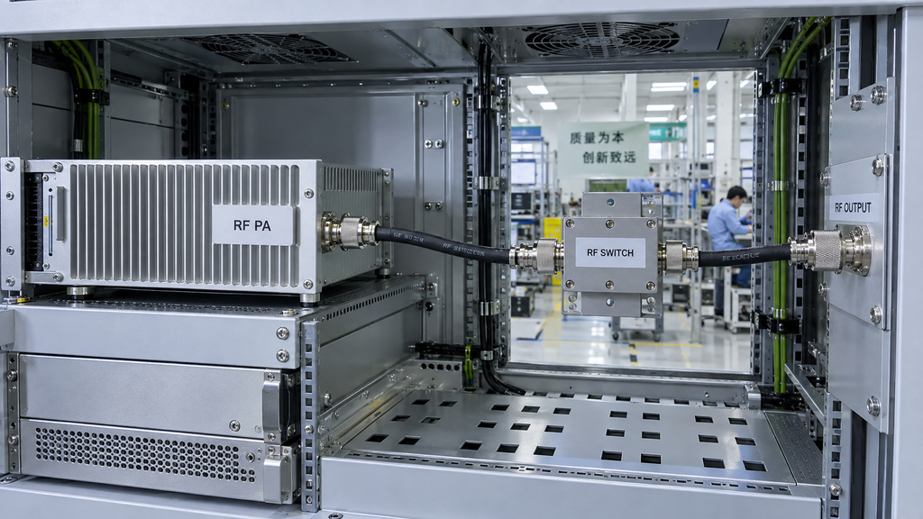
An RF switch’s power requirement depends on its position in the system and the conditions at its ports. A switch carrying a low-level signal faces different requirements from one exposed to a high-power amplifier output. Even in an output path, the PA’s catalog wattage does not necessarily describe the power at every downstream interface.
The relevant requirement belongs to a defined switch port, operating state, and RF reference plane. Without these details, comparing the switch’s advertised power rating with the PA’s nominal output can produce a misleading result.
Port state matters too. A selected transmission path and an unselected port may have different power limits. Depending on the switch design, an unselected port may be reflective or connected to an internal termination. The manufacturer’s ratings must cover whichever conditions are relevant to the intended application.
In multi-channel C-UAS cabinets, several RF paths and operating states may place different requirements on switching components. A single headline rating cannot establish that every applicable port condition is supported.
The first task is to define the RF conditions at the switch interfaces. This includes the power definition, relevant ports, and operating states. These requirements form the basis for comparing candidate specifications.
That assessment is separate from confirming the physical RF path. Cabinet RF routing verification establishes whether the intended connections and paths are correct. Switch qualification determines whether the component is rated for its assigned conditions.
If the switch location, port state, or RF power requirement remains undefined, the selection lacks a reliable basis. The component may be suitable, but the available information cannot establish that yet.
2. What Does the RF Switch Power Rating Actually Mean?
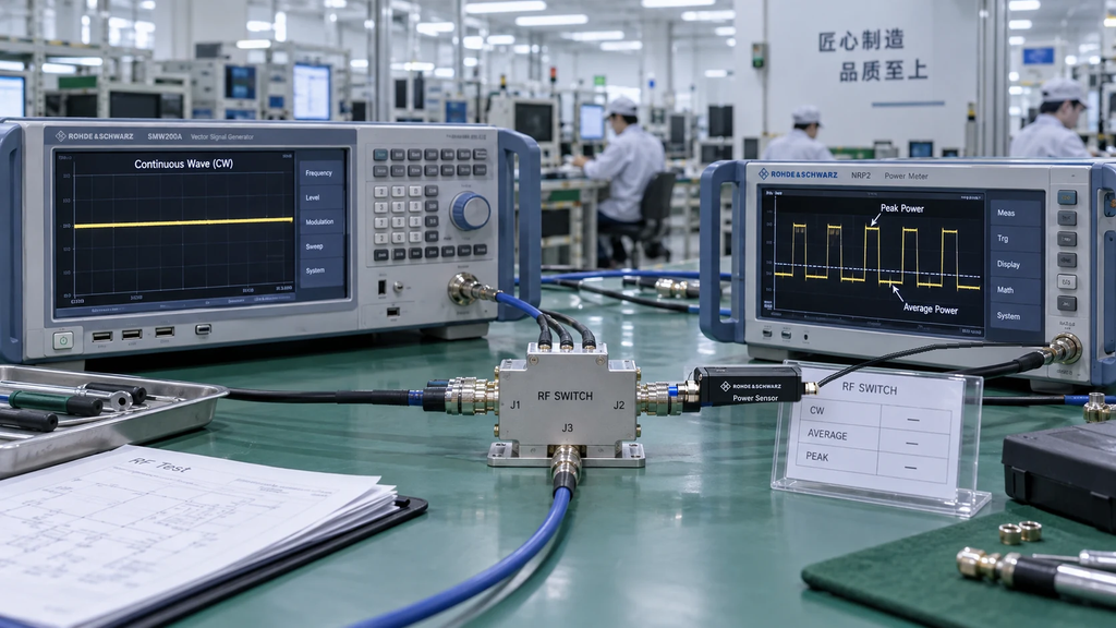
Manufacturers may specify continuous-wave power, average power, peak power, and separate limits for switching under RF power. These figures describe different operating conditions and should not be compared as though they mean the same thing.
Continuous-wave (CW) power refers to sustained operation with a continuous RF signal under specified conditions. Its applicability may depend on frequency, temperature, port configuration, and load.
Average power describes power averaged over a defined interval. For a signal whose amplitude changes over time, the waveform matters because two signals with the same average power can produce different peak electrical stresses.
Peak power describes the highest applicable power level under the manufacturer’s stated conditions. A high peak rating cannot establish continuous-power capability unless the published specifications expressly support that use.
The distinction is easy to miss when comparing product sheets. Suppose two switches advertise the same maximum wattage. One may specify continuous operation at a defined temperature, while the other quotes a peak limit for a restricted waveform. The numbers match, but the supported operating conditions do not.
Rated and typical values need similar care. A typical measurement describes performance under representative conditions. It should not be treated as a guaranteed operating limit unless the manufacturer defines it that way.
The switch technology also matters. Electromechanical and solid-state designs have different physical limitations. Their ratings need to be interpreted using the applicable manufacturer specifications rather than a common assumption about wattage.
Before comparing candidates, engineers should align the power definition, waveform, frequency range, port state, load, and thermal conditions. Where these details are missing, the candidates are not yet fully comparable.
The result may be an incomplete comparison rather than a failed product. A supplier can resolve that uncertainty by providing the relevant rating definition and its operating limits.
3. Can a Switch Handle RF Power but Fail During Switching?
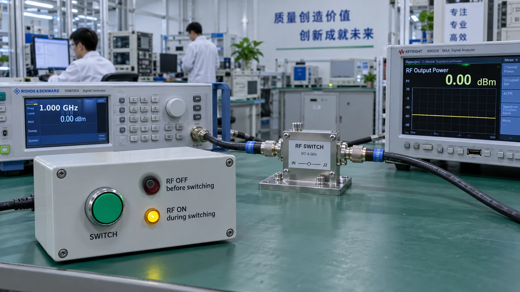
Yes. A switch may carry the required RF power in a stable state but lack the rating needed to change states while that power is present.
Manufacturers distinguish between hot switching, where RF power is present during a change of state, and cold switching, where RF power is removed during that operation.
For an electromechanical switch, changing contacts under RF power can introduce arcing and contact wear, depending on the electrical conditions. Solid-state switches avoid mechanical contacts but have their own semiconductor-related operating limits.
These differences make switching-state ratings important. A manufacturer’s continuous-power specification may describe power handling through an established connection without establishing the maximum permitted power during switching.
Consider a supplier that provides a CW power rating but no hot-switching rating. If the intended application requires switching with RF power present, the CW specification cannot settle the selection. The supplier needs to provide evidence covering that particular operating condition.
Even a published hot-switching rating has limits. It applies to the stated frequency, signal, port, and environmental conditions. A rating obtained under one set of conditions should not be extended to another without supporting information.
Switch power qualification also has a different purpose from system control verification. RF PA frequency switching verification addresses whether the larger system reaches its intended RF state. A switch’s power specification cannot establish that result.
Engineers should therefore evaluate stable-state power handling and switching-state power handling separately whenever both are required. Approval of one condition provides no substitute for evidence covering the other.
4. How Do Insertion Loss and VSWR Change the Decision?
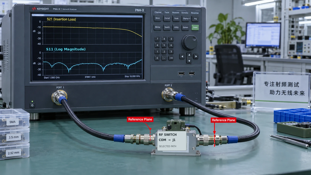
A switch may meet its power-handling requirement yet introduce too much transmission loss or insufficient impedance matching for the intended RF path.
Insertion loss measures the reduction in transmitted RF power through a defined switch path under specified test conditions. It is normally expressed in decibels and may change with frequency or switch state.
The resulting transmission loss affects the power available beyond the switch. But the difference between incident and transmitted power should not automatically be treated as heat generated inside the component. Reflections caused by impedance mismatch can also influence the measured result.
VSWR and return loss describe how well an RF port is matched under stated measurement conditions. They are useful when evaluating interface performance, but they answer a different question from power handling under a mismatched external load.
A switch with good port VSWR does not necessarily have a high tolerance for reflected power. That tolerance needs its own applicable rating or qualification evidence.
Likewise, acceptable insertion loss does not guarantee acceptable port matching. Both must be checked against the relevant project requirements.
The measurement reference plane is important here. Data measured at a switch connector cannot be applied directly to another location in the RF path without considering the intervening components.
Frequency coverage also needs attention. A favorable insertion-loss figure at one frequency does not establish equivalent performance throughout the specified range. Small-signal transmission measurements cannot replace high-power qualification data either.
When comparing switches, engineers need data measured under compatible frequency, port-state, and reference-plane conditions. A comparison based on mismatched test conditions may exaggerate differences between products or conceal a limitation.
Power handling, insertion loss, and impedance matching are separate requirements. A candidate should satisfy each applicable requirement rather than relying on a favorable result in one category.
5. Why Do Isolation and Unused-Port Ratings Matter?
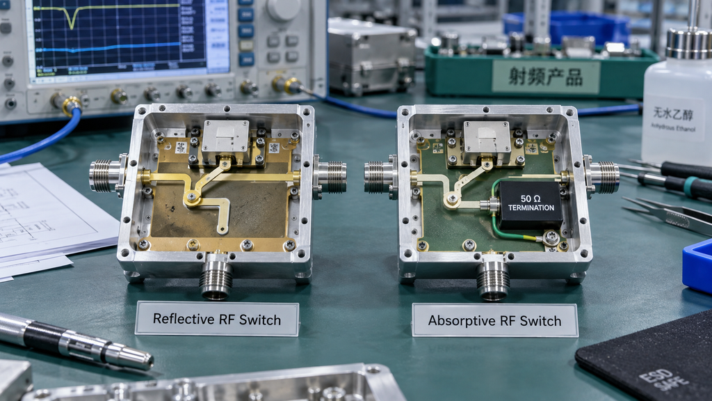
Isolation describes how much RF transmission is reduced between specified ports when the switch is in a particular state. It is usually expressed in decibels.
High isolation can be useful, but it does not establish how much power an unselected port or internal termination can withstand.
The distinction is especially relevant when comparing reflective and absorptive switches.
In a reflective switch, an unselected path generally presents a reflective impedance rather than a matched termination. In an absorptive switch, an internal termination provides a defined impedance for the relevant unselected path.
That termination has a physical power limit. It may have different continuous, peak, or thermal ratings from the selected transmission path.
For example, a manufacturer may specify a particular power-handling capability for the selected RF path while assigning a lower limit to an internal termination. The main path rating cannot be applied to the termination without evidence supporting that use.
A reflective architecture has different characteristics, but that alone does not make it unsuitable. The appropriate choice depends on the port behavior required by the project and the limits documented for the specific device.
This is why a specification listing excellent isolation may still be incomplete for power qualification. Engineers may also need the port configuration, termination type, and power ratings applicable to selected and unselected states.
RF switches should not be confused with isolators or circulators. Although all these components involve RF transmission or isolation, they serve different functions. The decision about when an RF PA chain needs an isolator or circulator requires a separate assessment.
For the switch itself, the selected-path rating, isolation performance, and unselected-port power limits should be examined as distinct specifications.
6. What Changes Under Heat and Reflected Power?
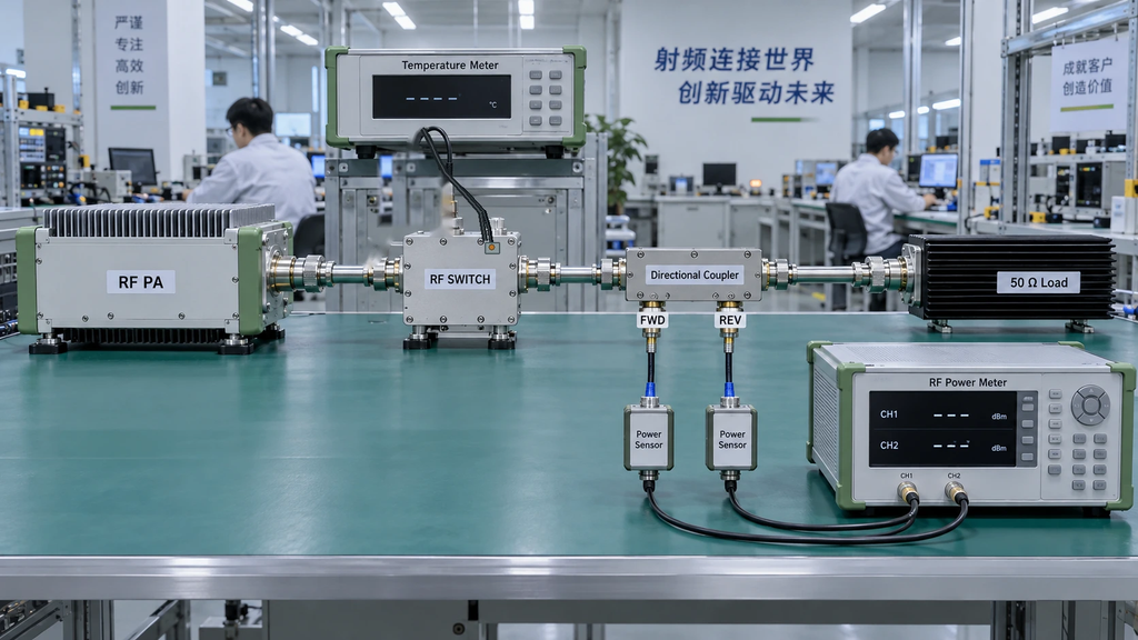
An RF switch’s rated power may change with operating temperature. Its actual temperature depends on the installation environment, internal losses, nearby heat sources, and operating conditions.
In an enclosed C-UAS cabinet, the temperature around an RF switch may differ from the cabinet’s general ambient temperature. A published rating tied to ambient or case temperature must therefore be interpreted using the manufacturer’s temperature definition.
Operating duration matters as well. A brief evaluation at a particular temperature does not establish continuous operation under a hotter condition. The supporting evidence needs to cover the required thermal state and operating duration.
Load mismatch introduces a separate concern.
When an external load is mismatched, reflected RF waves change the electrical conditions at the switch interfaces. Depending on the impedance and device design, voltage or current stresses may differ from those represented by a matched-load rating.
The switch’s port VSWR specification cannot establish how much external load mismatch it can tolerate at RF power. Matching performance and mismatch power tolerance require different evidence.
A PA’s VSWR protection does not settle the question either. That protection operates according to the PA manufacturer’s design and specified conditions. It does not certify the downstream switch against every possible reflected-power or thermal stress.
For qualification, the relevant evidence may include temperature-dependent ratings, manufacturer-defined load limits, or applicable test records. Each document should be used within the conditions it covers.
If the supplier provides only room-temperature, matched-load data, that evidence cannot establish suitability for sustained hot-state or mismatched-load operation.
The correct response is to identify the unsupported requirement and request the corresponding documentation. The missing evidence does not prove that the switch will fail, but it leaves the qualification unresolved.
7. What Evidence Makes an RF Switch Acceptable for the RF Chain?

A defensible switch selection links the project’s requirements to the manufacturer’s stated limits and the evidence supporting them.
The review should distinguish three outcomes. A requirement is supported when the applicable evidence covers it. An evidence gap exists when an essential condition has not been documented. A requirement is outside the rated scope when the available specifications show that it exceeds the manufacturer’s stated limits.
These distinctions matter during supplier evaluation. Missing documentation may be resolved without changing the product. A documented rating conflict requires a different engineering or procurement decision.
The following matrix provides a record for that assessment. It contains no assumed qualification results. Actual project requirements, manufacturer ratings, and evidence references must be entered before a candidate can be assessed.
RF Switch Qualification Matrix
| Review Item | Actual Project Condition | Switch Rated Condition | Evidence Required | Qualification Decision |
|---|---|---|---|---|
| Frequency coverage | Enter required frequency range and relevant ports | Enter supported range and applicable limits | Current manufacturer specification | Does the rated range cover the requirement? |
| CW / average power | Enter sustained power, waveform, and operating condition | Enter corresponding CW or average-power rating | Rating with frequency, load, and temperature conditions | Is sustained operation supported? |
| Peak power | Enter peak requirement and signal characteristics | Enter peak limit and applicable restrictions | Manufacturer peak-power specification | Does the peak rating cover the required condition? |
| Switching condition | Enter required switching state and RF exposure | Enter applicable hot- or cold-switching rating | Manufacturer switching-power documentation | Is the required switching condition supported? |
| Selected / unselected ports | Enter relevant port states and termination requirements | Enter port-specific and termination ratings | Port configuration and power specifications | Are all required port states covered? |
| Insertion loss | Enter acceptable loss across the required frequency range | Enter loss specifications for relevant paths and frequencies | Manufacturer transmission data | Is transmission loss within the project limit? |
| Isolation | Enter required isolation between relevant ports | Enter corresponding isolation specification | Manufacturer isolation data | Does isolation meet the stated requirement? |
| Port VSWR / return loss | Enter matching requirements at defined interfaces | Enter applicable port matching specifications | Port-specific VSWR or return-loss data | Is the required matching performance supported? |
| Load-mismatch power tolerance | Enter relevant external load and reflected-power conditions | Enter manufacturer-supported mismatch limits | Applicable load-tolerance or qualification evidence | Is operation under the required load condition supported? |
| Thermal operation | Enter required temperature and operating duration | Enter temperature-dependent limits | Rating, derating data, or qualification records | Is the required thermal condition covered? |
Each row needs a recorded result and an evidence reference. A numerical pass should not be entered merely because a supplier advertises a higher wattage.
The matrix also keeps related conditions separate. Port VSWR is evaluated independently of load-mismatch power tolerance. Static power handling and switching under RF power have different entries. A favorable result in one row cannot fill an evidence gap in another.
Two suppliers may be comparable for frequency coverage yet not comparable for hot-switching capability if one has not published the relevant rating. The comparison should state that limitation rather than produce an unsupported overall ranking.
Evidence scope matters after the initial selection too. A general specification, a representative test result, and a record linked to a delivered unit support different claims. Where the contract requires serial-number-linked or batch-specific evidence, that requirement should be defined explicitly.
The same boundary applies to adjacent components. A PA test report cannot qualify an external RF switch. Similarly, controlled-load measurements and installed-path measurements may establish different aspects of performance, as discussed in dummy load testing versus real antenna chain checks.
A completed qualification record should identify which requirements are supported, which remain open, and which conflict with the published ratings. Procurement and engineering teams can then resolve specific issues without treating every missing document as a product failure.
Conclusion
RF switch power rating matters in a C-UAS jamming chain because the manufacturer’s wattage figure is valid only within its stated operating conditions. A switch suitable for steady-state transmission may have different limits during switching, at elevated temperatures, or under mismatched-load conditions.
Matching the switch’s advertised wattage to the PA’s nominal output is therefore insufficient. The selection needs evidence that covers the actual power definition, relevant ports, switching conditions, and environmental requirements.
Before approving a candidate, complete the qualification matrix using the project’s requirements and the manufacturer’s applicable specifications. Record missing evidence and rating conflicts separately. This supports a component-level decision, but it cannot replace project-specific verification or certify the complete RF system.
For projects involving RF PA modules and externally selected switching components, RF SKYPOWER‘s engineering team can review the PA product and interface requirements. Share the operating frequency range, PA output conditions, waveform and switching requirements, RF interface boundaries, load assumptions, thermal conditions, and expected evidence scope. The discussion can then focus on the applicable PA requirements while keeping third-party switch qualification and final system acceptance within their proper responsibilities.