










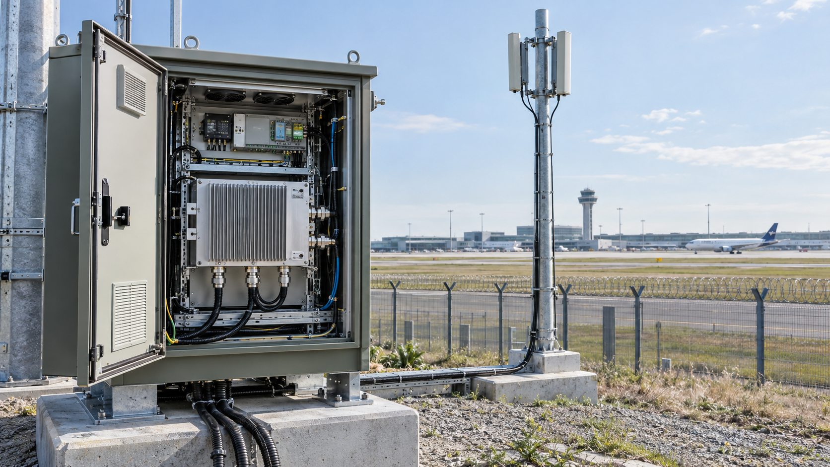
Airport RF PA requirements can be very different when the same amplifier hardware is deployed in a perimeter C-UAS installation. Long standby periods, heat buildup inside outdoor cabinets, remote fault reporting, and limited maintenance access all affect how the PA should be specified and tested. A different amplifier technology or higher power rating is not necessarily the answer.
One common mistake is treating 24/7 airspace monitoring as 24/7 RF transmission. An airport security system may monitor continuously while its amplifier remains powered off, stays in standby, or operates periodically under authorized conditions. Each operating profile places different demands on the hardware.
The published frequency and power ranges of RF Power Amplifier Modules help narrow the initial choices. They cannot tell an integrator whether a module will meet the requirements of a particular airport installation.
Before comparing models, the project team needs to establish what the amplifier must do during normal operation, what happens when a fault occurs, and which test results are needed to support the selection.
1. What Operating Profile Does an Airport Perimeter RF PA Actually Need?
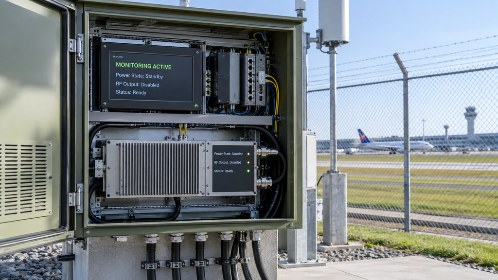
An airport perimeter system can monitor continuously while its RF power amplifier remains inactive. The monitoring period, PA power-on period, RF enable state, and actual RF output duration should be specified separately.
For example, a central controller may remain online while a remote PA is powered off. Another installation may keep the amplifier powered with RF output disabled so that its status remains available to the controller. Where permitted, the PA may operate for defined intervals before returning to standby.
These arrangements produce different DC loads, thermal conditions, and control requirements.
| Operating State | RF Output Condition | Duration / Frequency | Operating Boundary to Record |
|---|---|---|---|
| Monitoring active, PA unpowered | No RF output from the PA | Project-defined monitoring period | Controller status, PA power state and availability indication |
| Powered standby | RF output disabled; power and control circuits may remain active | Continuous or project-defined standby interval | Standby current, temperature, readiness and alarm status |
| Periodic RF enable | RF output permitted only within authorized operating conditions | Defined active duration, frequency and recovery interval | Enable state, actual RF output, current and thermal response |
| Continuous RF output | Sustained RF output only where legally authorized and specified | Project-defined uninterrupted interval | Waveform, output reference plane, voltage, temperature and protection behavior |
| Fault or protection state | RF output inhibited or limited according to verified protection logic | Event-driven | Fault source, reported state, event record and recovery permission |
An RF power amplifier duty cycle rating, including 100% continuous-wave operation, applies only under the manufacturer’s specified conditions. It does not establish performance for every waveform, ambient temperature, load, or cooling arrangement.
The required operating profile should identify the RF signal conditions, active duration, standby intervals, and expected recovery behavior. The integrator also needs to distinguish between a command to enable RF output and evidence that the PA has produced the required output.
Legal authority belongs in the operating specification as well. The project must identify which entity is authorized to conduct any RF mitigation activity and what spectrum and aviation-safety conditions apply. Operating an airport facility does not, by itself, establish permission to operate RF mitigation equipment.
The broader C-UAS RF power amplifier module selection process covers general frequency, power, control, and integration requirements. An airport project must then translate its actual operating schedule into module requirements.
Until the permitted operating states and required durations are defined, two modules with the same continuous-duty rating cannot be meaningfully compared for that application.
2. How Do Outdoor Cabinets Change Thermal and DC Requirements?
An amplifier operates under the conditions inside its cabinet, which may differ considerably from the outdoor temperature listed in a site survey.
Consider the same PA installed in two locations. On an open laboratory fixture, it has controlled room temperature and adequate cooling. Inside a sun-exposed outdoor cabinet, it may share a heatsink or ventilation path with other equipment. Both installations could produce the same RF output during an initial test, yet reach very different temperatures during extended operation.
Solar loading, enclosure construction, internal airflow, nearby equipment, and the thermal path from the PA to its mounting surface all affect heat buildup.
Even periodic operation can create cumulative heating. If the interval between active periods is too short for the assembly to cool, each cycle may begin at a higher temperature. A powered PA in standby can also continue dissipating heat through its auxiliary circuits.
For reliable comparison, engineers need to distinguish cabinet air temperature, heatsink temperature, PA housing temperature, and readings from internal module sensors. A reported temperature is useful only when its measurement location is known.
Environmental protection extends beyond temperature
Outdoor cabinets also face humidity, condensation, water and dust ingress, and changing weather conditions.
A sealed enclosure may prevent direct water entry but still experience condensation as internal surfaces cool. The project should therefore define its environmental exposure and determine how enclosure sealing, drainage, moisture control, and cooling affect the installed PA.
The module supplier is responsible for demonstrating performance within the conditions it specifies. The integrator must confirm that the enclosure provides those conditions, unless the supplier’s contracted scope includes the complete cabinet.
An RF amplifier environmental test can support only the conditions it actually covers; it cannot qualify the entire outdoor installation.
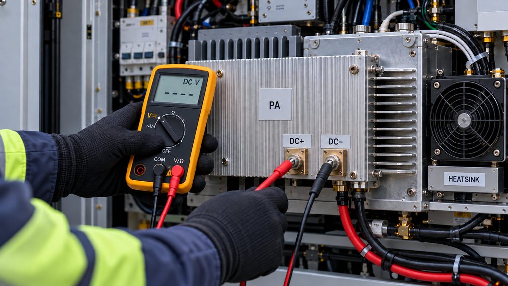
DC voltage must be checked at the PA
RF amplifier power supply requirements must be verified at the PA terminals, because a nominal 28 V DC supply does not guarantee that 28 V reaches the amplifier under load.
Connectors, cable resistance, protection devices, and shared distribution paths introduce voltage drops. Startup and switching events may also produce transients that steady-state measurements will miss.
For modules designed around a nominal 28 V supply, the useful measurement is the voltage at the PA terminals under the relevant load. The specified operating range and any transient limits must be checked against the actual power distribution design.
Cold-state measurements are similarly limited. A PA that meets its output requirement immediately after startup may behave differently once the cabinet and heatsink reach their sustained operating temperatures.
The continuous RF output verification guide examines how test duration, cooling, supply conditions, and measurement setup affect sustained-output evidence.
An airport RF PA specification should therefore describe the expected thermal environment, cooling interface, duty profile, and loaded DC conditions. Those details give the supplier a basis for demonstrating suitability instead of relying on a broad claim of outdoor compatibility.
3. How Do Remote Antenna Locations Change RF Path Requirements?
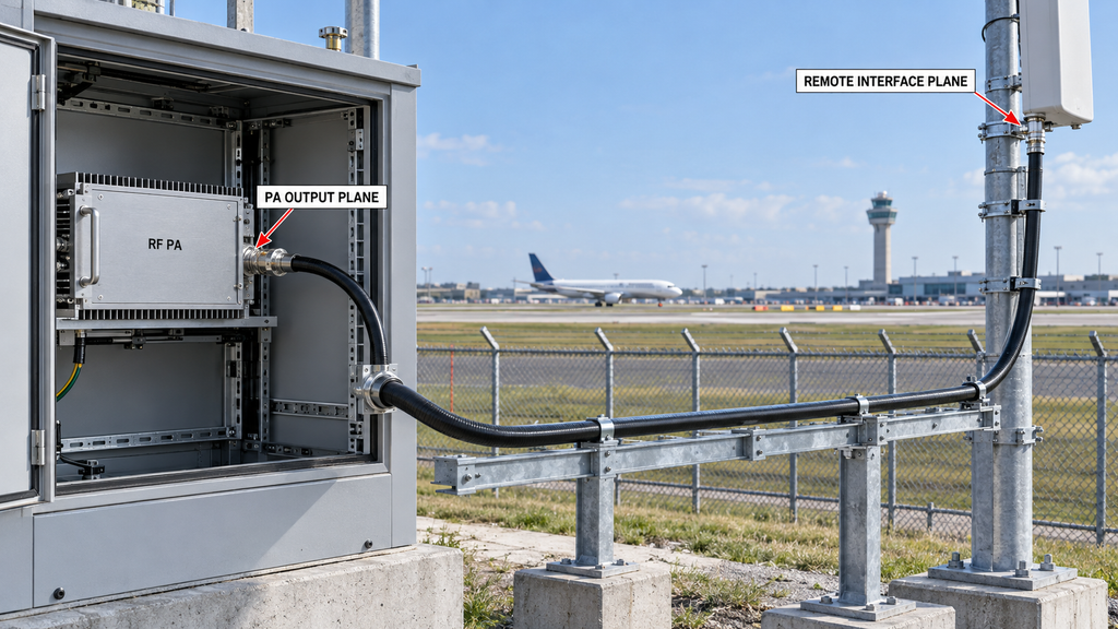
Airport perimeter installations may separate amplifier cabinets from antennas and other RF equipment. Once additional cables and interfaces are introduced, the module’s measured output and the behavior of the installed RF path become different engineering questions.
A PA may meet its rated output during a factory test into a matched 50 Ω load. That result establishes performance at the defined test reference plane. It does not establish how much power will be present at a remote interface after the installed feeder, connectors, and other components are included.
Define the RF measurement reference plane
A supplier might specify output power at the PA connector while the integrator needs to evaluate a downstream equipment interface. These are different measurement locations.
Any comparison must account for the intervening path and the conditions under which the measurements were taken.
The RFQ should therefore identify the module output connector, required measurement reference plane, and responsibility for downstream equipment. This avoids disputes when factory measurements and installed-system results appear different.
Account for mismatch and protection behavior
An installed RF path can change over time. Connector damage, moisture ingress, or deterioration in downstream components may alter the load presented to the amplifier.
A mismatch can increase reflected power and trigger protection, power limiting, or shutdown, depending on the PA design. Such protection may prevent damage, but it can also interrupt the required operating state.
Cable loss, load mismatch, and reflected-power protection should be evaluated as separate conditions. A matched-load PA test does not demonstrate installed-path performance or establish how the module will respond to an out-of-spec load.
The project should define which load conditions the supplier must verify and which installed-path checks belong to the integrator.
Remote equipment must also be maintainable. Connector accessibility, mounting hardware, environmental protection, and inspection access can determine whether a module can be checked or replaced without extensive cabinet work.
The supplier can provide module-port specifications, mechanical drawings, and verified protection information. The integrator remains responsible for the installed RF path unless the agreement assigns that work elsewhere.
If the measurement reference plane or RF interface boundary is unclear, the buyer should resolve it before comparing output claims.
4. What Remote Alarms and Recovery States Are Required?

A remote fault indicator is useful only if the operator knows which module reported it, what the signal means, and whether the information is current.
A cabinet may report power status, temperature, protection events, readiness, or communication health. The available signals depend on the module and its interface specification.
A single alarm flag may not reveal whether the PA has shut down because of temperature, load protection, or another condition. Maintenance personnel need enough information to decide whether the problem requires inspection, cooling, a controlled reset, or replacement.
Communication loss creates another risk. If the controller loses contact with a module, the last reported healthy state should not continue to appear as a valid current reading.
The monitoring design should identify each module, distinguish invalid or missing status from a confirmed healthy state, and retain the information needed to investigate faults.
Recovery needs its own rules
Clearing a temperature alarm does not prove that the amplifier has returned to its required RF operating condition. Re-establishing communication also does not authorize RF output to resume.
The system must define when recovery is permitted and how the controller distinguishes a cleared fault from a module that is ready for normal operation.
RF SKYPOWER modules can be evaluated against their documented control, protection, and status interfaces. The exact signal meanings and recovery behavior must be checked for the selected configuration.
The RF PA status feedback mapping guide covers the detailed verification of module identity, reported states, and controller interpretation.
For an unattended airport cabinet, remote monitoring should provide enough verified information to support maintenance decisions. An alarm interface alone does not demonstrate that capability.
5. How Should Maintenance Interval and Redundancy Be Specified?
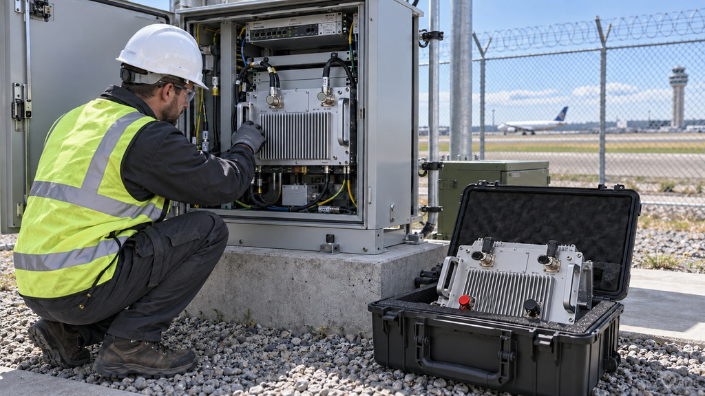
Limited access to remote airport cabinets makes maintenance planning part of the equipment specification.
A failed module might be easy to replace on a workbench but difficult to service at a perimeter location. Access arrangements, connector placement, mechanical mounting, and the availability of compatible hardware can all affect the repair.
The RFQ should identify expected inspection intervals, fault-triggered maintenance requirements, replacement constraints, and the information needed to select compatible spare modules.
Hardware revision control matters when multiple cabinets use nominally identical units. A replacement must match the required electrical, RF, mechanical, and control interfaces. The same nominal power rating does not guarantee interchangeability.
Spare inventory and installed redundancy solve different problems
A replacement module kept in storage can reduce some maintenance delays. It cannot prevent an interruption while the failed equipment is being replaced.
An installed redundant path may support a higher availability target, but that depends on the entire system. Shared power supplies, controllers, cooling arrangements, or RF interfaces can create common failure points.
Whether redundancy is required depends on the project’s acceptable interruption, maintenance access, and reliability objectives. It should not be added merely because the installation is at an airport.
The same distinction applies to maintenance intervals. A continuous-duty rating does not establish an inspection schedule, failure rate, or guaranteed service life.
Before comparing reliability claims, engineers should obtain data relevant to the intended environment and operating profile. Where such evidence is unavailable, the maintenance objective remains a project requirement rather than a proven module capability.
The supplier can support this review with interface drawings, revision records, and applicable qualification information. Site availability remains a system-level responsibility.
6. What Evidence Proves Long-Duty RF PA Readiness?
The value of a test report depends on the claim it supports.
A datasheet provides published operating limits. A short laboratory test can show RF output, gain, or control behavior under defined conditions. An RF amplifier reliability test needs a defined operating profile and observation period, while production burn-in may help identify certain manufacturing or early-life issues.
These documents answer different questions. None should be used as an unrestricted guarantee of long-term field reliability.
For sustained RF output, the relevant evidence should identify the waveform, test duration, load, supply voltage at the module, cooling arrangement, thermal state, and output measurement reference plane.
A periodic operating requirement needs evidence that reflects the agreed active and inactive intervals. A continuous-wave test under different conditions may still provide useful information, but its limitations must be understood.
Airport environments require spectral evidence
Airport applications can impose additional concerns about unwanted emissions and electromagnetic compatibility with nearby aviation services.
Module-level RF measurements may characterize harmonic, spurious, and other unwanted emissions under a defined signal, load, and operating condition. Those results should be evaluated against the requirements applicable to the project.
An installed system includes more than the PA. Its RF components, cabling, enclosure, grounding, and operating environment may introduce additional electromagnetic compatibility considerations.
The project must therefore distinguish module-level spectrum evidence from system-level verification and the applicable aviation-safety and spectrum authorization requirements.
A module test report cannot establish that the complete installation will avoid interference with aviation communications, navigation, or surveillance systems. Any required field verification must follow approved procedures and authorized operating conditions.
Traceable reports have a defined scope
An RF amplifier test report linked to a serial number connects the recorded measurements to a particular delivered module. This makes it easier to confirm which hardware was tested, under what conditions, and with what recorded outcome.
RF SKYPOWER’s One Report One Unit approach is relevant when a buyer requires traceable module-level delivery evidence. The RFQ should specify the required measurements, hardware revision, test conditions, and unit identification.
A report for one unit supports conclusions about that unit under the stated test conditions. It cannot establish the statistical reliability of an entire production batch or prove the performance of the installed airport system.
Factory acceptance and field verification should also remain separate. The supplier can demonstrate module behavior using controlled test equipment and defined loads. The integrator must verify the installed cabinet, electrical interfaces, RF path, and other contracted system conditions.
When reviewing two suppliers, check whether their results use comparable waveforms, operating points, temperatures, loads, and measurement reference planes. If one report lacks those conditions, ask for the missing information before drawing a performance conclusion.
Missing evidence leaves a decision unresolved. It does not establish that the module has failed.
How to Turn Airport Constraints into an RF PA RFQ
A useful airport RF PA RFQ begins with the operating conditions the project has already defined.
Before comparing modules, engineers need the authorized frequency requirements, signal conditions, available RF input drive, and required output power at a specified reference plane. They also need to state how long the PA must remain in each operating state and what conditions the installed equipment will experience.
The following table assigns each requirement to the evidence and responsible party needed for engineering review.
| Deployment Condition | Module Requirement | Verification Condition | Evidence Requested | Responsible Party | If Evidence Is Missing |
|---|---|---|---|---|---|
| Legal operating boundary | Compatible permitted states and documented control behavior | Approved project and operating conditions | Authorization requirements and control-interface documentation | Project authority and integrator | Hold active-operation approval |
| Authorized RF requirements | Defined frequency scope, signal conditions, input drive and required output reference plane | Agreed module operating points and test conditions | Module specifications and relevant RF performance reports | Integrator defines; supplier demonstrates module behavior | Do not finalize module selection |
| Standby and active-duty profile | Required standby, periodic or continuous operating capability | Specified waveform, operating state and duration | Operating specifications and corresponding test records | Integrator and supplier | Do not infer continuous-duty suitability |
| Outdoor cabinet environment | Defined cooling interface, thermal limits and environmental protection | Project-defined temperature, humidity, enclosure and cooling conditions | Module qualification data and applicable cabinet evidence | Supplier for module; integrator for enclosure | Hold environmental suitability judgment |
| DC supply conditions | Compatible voltage, current and applicable transient limits | Module-terminal voltage under relevant loads and operating events | Electrical specifications and loaded-supply evidence | Supplier and integrator | Reassess electrical compatibility |
| Remote RF interface and load | Defined connectors, output reference plane and protection behavior | Agreed module-port load and installed-path conditions | Interface documents, RF test data and applicable protection evidence | Supplier for module; integrator for installed path | Hold installed-path performance judgment |
| Remote monitoring and recovery | Identifiable alarm, status and protection behavior | Defined faults, communication validity and recovery permissions | Interface specifications and status verification records | Supplier for module; integrator for system logic | Hold unattended-recovery claims |
| Maintenance and replacement | Documented mounting, interface and revision requirements | Project-defined maintenance and replacement conditions | Mechanical documentation, revision records and maintenance plan | Supplier, integrator and project operator | Do not claim a guaranteed maintenance interval |
| Spectrum purity and EMC | Defined unwanted-emission evidence within module scope | Approved test conditions and applicable system-level requirements | Relevant RF emission data and required system-level assessments | Supplier for module evidence; integrator and competent authority for broader compliance | Hold compliance claims |
| Delivery and acceptance | Defined module test evidence and unit traceability | Agreed test scope, conditions and delivered-unit identity | Formal reports and applicable serial-number-linked records | Supplier for module; integrator for system acceptance | Request missing evidence before approval |
The table becomes useful when the project team replaces general requirements with actual operating conditions. Any unknown power targets, temperatures, duty profiles, maintenance intervals, or acceptance criteria should remain identified as missing inputs.
The review should keep three decisions separate. The supplier demonstrates whether the module meets its agreed specifications. The integrator verifies the installed equipment against the system requirements. The appropriate project authority establishes the legal and safety conditions for operation.
Those responsibilities may overlap contractually, but the evidence must still show what was tested and what has been approved.
RF SKYPOWER’s airport perimeter C-UAS solutions provide broader application context for engineering discussions. Module selection should proceed from the project’s RF and environmental requirements rather than from the application page alone.
Once the operating conditions and evidence requirements are clear, the engineering team can assess whether a standard RF PA module is suitable for further evaluation or whether a custom configuration is needed.
Conclusion
Airport perimeter C-UAS deployment can change RF power amplifier requirements even when the nominal frequency range and output power remain the same. Long standby periods, outdoor thermal conditions, remote interfaces, fault reporting, and maintenance access can all change what the module must withstand and what the supplier must demonstrate.
That does not automatically call for a different amplifier technology. The deciding factors are the authorized operating profile, actual RF duty, environmental and electrical limits, interface requirements, and supporting test evidence.
The most common specification error is treating a continuous-duty rating as proof of long-term, maintenance-free operation. A module may meet its factory specifications while the complete installation still requires further environmental, RF-path, reliability, and safety verification.
Start by documenting the operating states and completing the requirements-to-evidence table. Resolve missing conditions before comparing models, and assign module-level and system-level verification to the responsible parties.
Contact RF SKYPOWER Engineers to Review Your Airport RF PA Requirements. Provide the authorized operating requirements, signal conditions, available RF input drive, required output reference plane, cabinet environment, DC supply conditions, remote monitoring needs, maintenance objectives, and expected test evidence. RF SKYPOWER can use these inputs to assess relevant standard or custom RF power amplifier module options against the defined engineering requirements.