










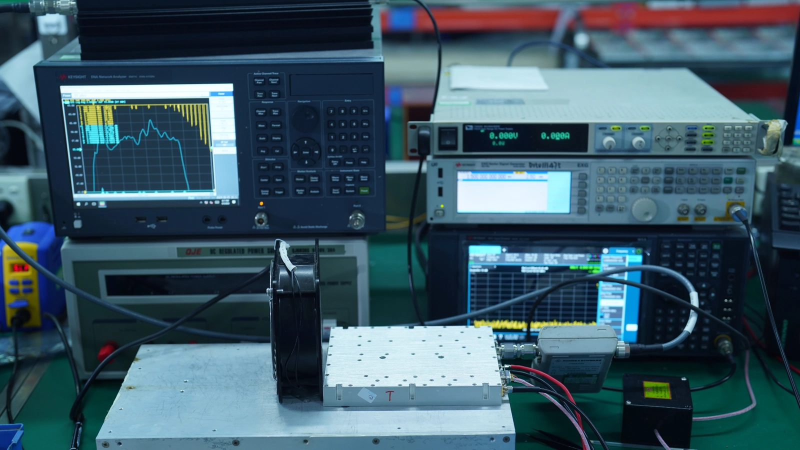
RF amplifier power control resolution describes how finely a control setting can be adjusted, but it does not establish how accurately the RF output follows that setting. A PA with nominal 0.5 dB steps may produce different output-power changes depending on its control architecture, operating point, and measurement conditions.
For C-UAS integrators comparing RF power amplifier modules, this difference matters when a system must switch reliably between defined RF output levels. A command may be accepted and its setting updated, yet the measured output may respond unevenly or remain nearly unchanged at certain operating points.
Before deciding whether 0.5 dB resolution is sufficient, engineers need to establish what the command adjusts and whether the resulting power change can be measured and repeated. The answer depends partly on whether control occurs through SDR drive, external attenuation, internal PA gain, or an output-power feedback loop.
1. What Does RF Amplifier Power Control Resolution Actually Mean?
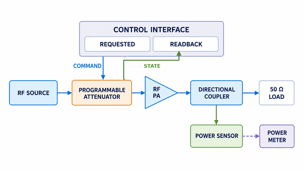
Power control resolution usually refers to the smallest selectable increment in a gain, attenuation, or power-control setting. A specified 0.5 dB step describes nominal setting spacing unless the specification also defines the corresponding measured RF output performance.
The adjustment location matters. An SDR may vary the signal entering the amplifier, a programmable attenuator may change the input signal level, or an internal gain-control function may adjust the PA itself. Some systems also use feedback to regulate output power toward a commanded target.
These arrangements require several parameters to be distinguished. Control step size describes the nominal difference between adjacent settings. Measured output step describes the resulting Pout difference in dB, while step error is the deviation from the expected signed change. Monotonicity indicates whether successive settings move output power in the intended direction, and repeatability describes how consistently a setting produces the same output under comparable conditions.
For digital step attenuators, step error and state error are also different. Step error concerns the change between attenuation states, while state error describes a specified state’s deviation from its defined reference. Neither establishes the absolute Pout accuracy of the complete RF PA chain.
Absolute output accuracy must be evaluated against a defined power target. The units also matter: dB expresses a relative change, while dBm expresses an absolute power level referenced to 1 mW.
The RF PA control interface should identify what the command changes and whether a reported value represents a requested setting, an active-setting readback, or an RF measurement. Without that distinction, nominal control resolution provides limited evidence of actual output performance.
2. What Can a 0.5 dB Control Step Actually Guarantee?
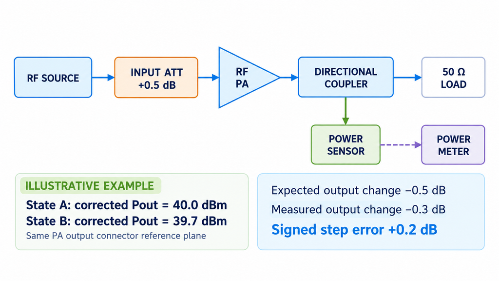
A nominal 0.5 dB step specifies the intended increment between selectable control settings. The actual RF output change depends on the complete signal path.
For two states measured at the same output reference plane:
Measured ΔPout (dB) = Pout,B (dBm) − Pout,A (dBm)
Step Error (dB) = Measured ΔPout − Expected Signed ΔPout
The expected change must include its direction. Increasing attenuation by 0.5 dB would normally produce an expected −0.5 dB output change in an otherwise unchanged linear signal path. Increasing gain would normally produce the opposite direction.
Consider a hypothetical measurement in which increasing attenuation by 0.5 dB changes corrected Pout from 40.0 dBm to 39.7 dBm. The actual change is −0.3 dB, giving a signed step error of +0.2 dB. This is an illustrative calculation, not an RF SKYPOWER test result, and its acceptability depends on the specified tolerance and measurement uncertainty.
Differences between nominal and measured steps can arise from gain compression, frequency-dependent attenuation errors, input-drive variation, supply conditions, or temperature. Near compression, for example, an increase in drive or gain setting may produce a smaller output change than expected.
Measurement uncertainty must also be considered. A power meter displaying a 0.48 dB change does not automatically prove that the physical output changed by precisely 0.48 dB.
A 0.5 dB control step therefore does not guarantee ±0.5 dB absolute output-power accuracy or identical step behavior across the adjustment range. Those characteristics require measurements under defined operating conditions.
3. How to Define the Usable RF Power Control Range
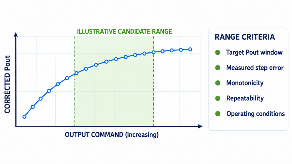
A wide nominal adjustment range does not necessarily mean every available setting provides useful output control.
Begin with the project’s required minimum and maximum Pout and the allowed deviation around each target. The next task is to identify which control states can produce those levels reliably.
At higher output levels, gain compression may reduce the effect of additional drive or gain. At lower levels, measurement uncertainty or signal-path characteristics may make small steps difficult to distinguish. Neither behavior should be assumed for a particular module without supporting data.
The control architecture determines how input power should be handled during testing. With internal PA gain control, actual Pin may remain constant while the internal setting changes. When an SDR or upstream attenuator controls power, actual Pin is part of the adjustment and must be recorded for the relevant states.
The SDR-to-PA drive margin must also support the required operating points. A setting that depends on unavailable input drive cannot be treated as a usable output state.
The usable control range is the portion of the available settings where measured Pout, step behavior, and repeatability satisfy the project’s requirements. Two modules with identical nominal steps may have different usable ranges because their actual RF responses differ.
4. How to Measure Actual Power Steps, Monotonicity, and Repeatability
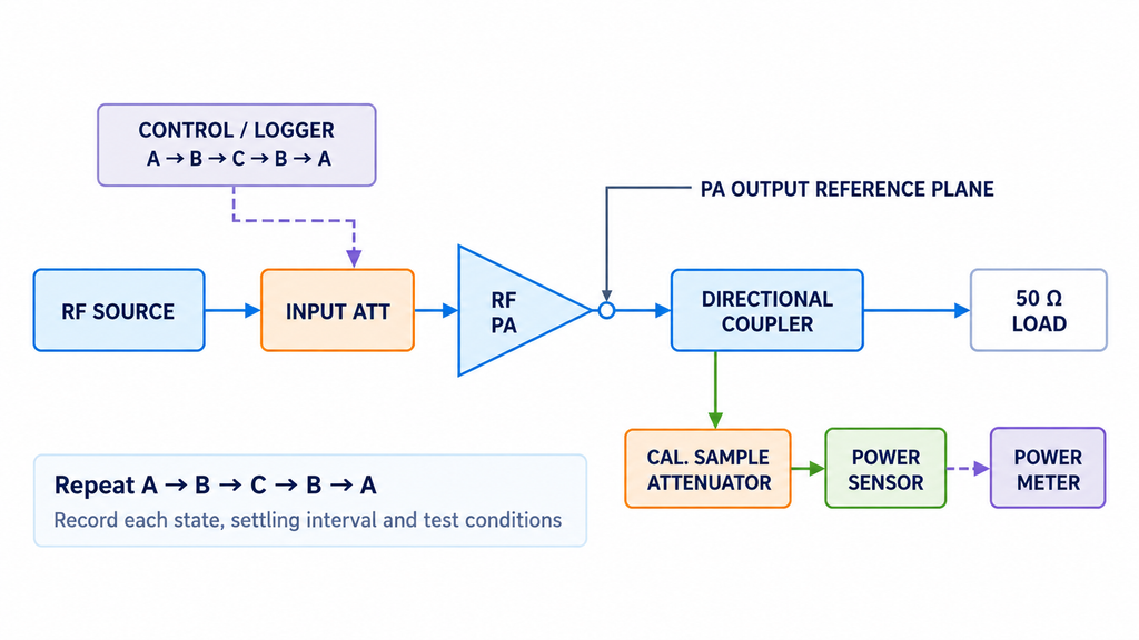
Power control resolution should be evaluated by measuring the RF output associated with defined control states. The test must establish a consistent output reference plane, protect the measurement instruments, and associate each power reading with the correct setting.
For conducted testing, connect the PA output through a suitably rated directional coupler to a power-rated 50 Ω dummy load. Route the forward-coupled sample through any required calibrated attenuation to an appropriate power sensor and meter. The RF components must withstand the applicable power and duty conditions, and the maximum sampled power must remain within the sensor’s input rating.
Define the reference plane, normally the agreed PA output connector, and correct the sample reading for coupling factor, path losses, and applicable calibration terms. Forward power, reflected power, and net delivered power must not be confused, particularly when mismatch is significant.
The test conditions should identify frequency, waveform, power definition, actual Pin or source-control condition, load, supply voltage, thermal state, settling time, and measurement uncertainty.
A practical verification uses an ascending and descending control sequence. Define states A, B, and C within the required operating range, measure A–B–C, then return through B to A. Record corrected Pout after the specified settling interval and repeat the sequence according to the approved test plan.
Adjacent readings establish the measured power steps. Their differences from expected signed changes establish step error, while the ordered results reveal whether the output changes monotonically.
Repeatability requires measurements from multiple visits to the same setting. Compare results obtained under comparable conditions and, where relevant, the same approach direction. Differences associated with approaching a setting from opposite directions should be reported separately rather than automatically treated as random repeatability variation. Temperature, supply conditions, and measurement drift should also be sufficiently controlled before attributing differences to control direction.
Power Control Step Verification Record
The table below shows one illustrative A–B–C–B–A sequence using nine engineering fields. It is a recording template, not actual RF SKYPOWER test data.
| Condition / Frequency | Command / Target Setting | Active Readback | Corrected Pout (dBm) | Measured ΔPout (dB) | Step Error (dB) | Monotonicity | Repeatability (dB) | Assessment |
|---|---|---|---|---|---|---|---|---|
| A / Baseline / f₁ | ___ | ___ / N/A | ___ | N/A | N/A | N/A | Pending | ___ |
| B / Ascending / f₁ | ___ | ___ / N/A | ___ | ___ | ___ | ___ | Pending | ___ |
| C / Ascending / f₁ | ___ | ___ / N/A | ___ | ___ | ___ | ___ | Pending | ___ |
| B / Descending / f₁ | ___ | ___ / N/A | ___ | ___ | ___ | ___ | Pending | ___ |
| A / Descending / f₁ | ___ | ___ / N/A | ___ | ___ | ___ | ___ | Pending | ___ |
Swipe horizontally to review all nine fields →
A complete test record must retain the individual readings for every required repetition cycle. Repeatability results should use the statistic and number of observations defined in the test plan, such as standard deviation or maximum-to-minimum spread. A single five-state sequence is insufficient for establishing a statistically supported repeatability result.
For each state, retain its associated command, available readback, corrected Pout, and actual Pin or source-control record. This is particularly important when SDR drive changes between settings. Shared test conditions and measurement corrections may be documented separately, provided they remain traceable to the corresponding state records.
A command acknowledgement or active-setting readback does not prove the resulting RF output. The RF PA gain feedback discussion explains why setting information and independently measured power must remain separate.
Measurement uncertainty should be evaluated for the difference between power readings, including relevant correlations between calibration and correction terms. Instrument display resolution alone does not establish the uncertainty of a measured power step.
If the uncertainty prevents a reliable distinction between adjacent states, the intended control resolution has not yet been demonstrated. The appropriate response is to obtain better evidence or improve the measurement method rather than automatically classify the module as defective.
5. What Changes Power Control Repeatability Across Frequency and Heat?
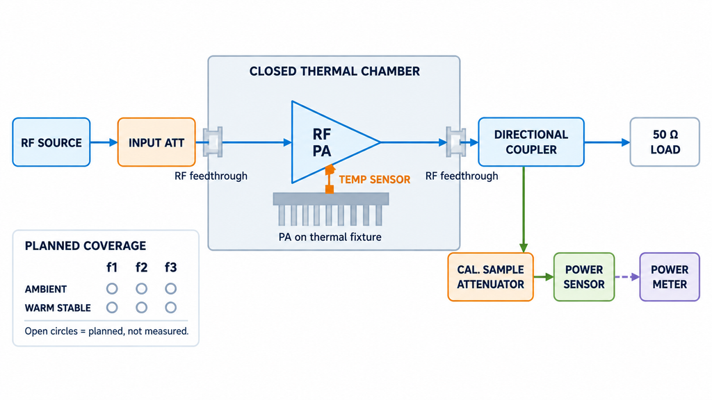
A power-control result measured at one frequency and temperature cannot automatically establish performance across the entire operating range.
Frequency may affect PA gain and the response of the adjustment network. Even when the nominal control step remains constant, the measured output change can vary between operating points.
Temperature introduces another variable. Component characteristics, supply behavior, and protection conditions may influence the RF response as the module warms. The direction and magnitude of any change must be determined from measurements rather than assumed.
Measurement timing matters as well. A command may be acknowledged before the output reaches a stable measurement state. For configurations using AT commands, the AT command timing verification process addresses this distinction. Other interfaces require equivalent timing definitions based on their own specifications.
For multi-frequency or extended-operation projects, identify the critical frequencies, output levels, and thermal states that require verification. A room-temperature result at one frequency remains evidence for that condition unless broader measurements support a wider conclusion.
6. How to Decide if the Control Resolution Meets C-UAS Requirements
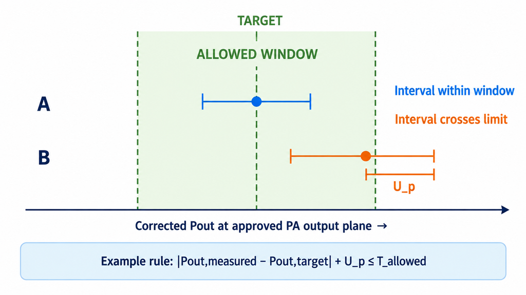
Control resolution is sufficient when the available RF output states can meet the project’s required power targets within the specified limits.
The decision should consider measured Pout, step error, monotonicity, repeatability, and measurement uncertainty. A module with fine nominal steps may still fail to reach a required target, while a coarser adjustment may be entirely suitable for an application with a wider acceptable output window.
Acceptance criteria should be established before testing. For example, a project may choose a conservative guard-banded rule for an absolute output-power target:
|Pout,measured − Pout,target| + U_P ≤ T_allowed
Here, measured and target Pout are expressed in dBm, their difference is in dB, U_P is the expanded power-measurement uncertainty under the defined method and coverage, and T_allowed is the permitted absolute deviation in dB.
The same conservative principle can be applied to step error by comparing its absolute value, plus the uncertainty of the measured power difference, against the approved step-error limit. That uncertainty calculation must account for relevant correlations between measurements.
These are examples of possible acceptance rules, not universal RF PA specifications or RF SKYPOWER acceptance limits. The project’s documented decision rule determines whether a result is accepted, rejected, or requires further evidence. Failing a conservative acceptance inequality does not automatically prove that the product is defective.
Monotonicity and repeatability also require predefined limits and measurement methods. A control setting that reaches the correct output once may still be unsuitable if repeated operation produces unacceptable variation.
For systems with multiple RF paths, each relevant path needs appropriate verification. Candidate configurations can only be compared meaningfully when their frequency, waveform, power definition, input conditions, reference plane, thermal state, and measurement methods are sufficiently aligned.
Step accuracy alone also does not prove closed-loop stability. Feedback validity, sampling intervals, controller behavior, and dynamic response require separate evaluation where automatic output-power regulation is used.
The engineering result should identify the verified usable control range, the conditions under which it applies, and any missing evidence that prevents a final decision.
What Power Control Evidence Should Buyers Request Before RFQ?
An RFQ that specifies only adjustable output power leaves the actual control-performance requirements open to interpretation.
Buyers should define the adjustment method, operating frequency, waveform, target Pout window, nominal step size, permitted step error, repeatability limit, and required settling time. The request should also identify input-drive conditions, output reference plane, load, DC supply, thermal state, measurement uncertainty treatment, and expected verification records.
A published control-setting specification establishes the stated adjustment capability, but measured performance requires additional evidence.
For example, RF SKYPOWER’s published 300–1700 MHz configurations HZ3001700-100, HZ3001700-150, and HZ3001700-200 list a 20 dB gain-adjustment range with nominal 0.5 dB steps. These figures describe the published settings of the corresponding configurations. They do not establish a universal output-step accuracy across all frequencies, temperatures, or operating points.
Where acceptance depends on measured performance, buyers should request the relevant control definitions and condition-specific RF records. Hardware and firmware revisions should also be identified when they affect control behavior.
Evidence requirements should match the procurement stage. A representative engineering test may support an initial configuration review, while individual-unit acceptance requires records associated with the relevant delivered units and agreed test conditions.
Once the requirements are defined, RF SKYPOWER’s engineering team can review the intended control architecture and available module configurations against the project’s technical needs. Model-specific suitability must still be supported by the applicable evidence.
Conclusion
A nominal 0.5 dB control step does not guarantee 0.5 dB output-power accuracy. RF amplifier power control resolution is suitable for a C-UAS application when the measured output states provide sufficient control over the required power range and satisfy the project’s limits for step error, monotonicity, and repeatability.
That judgment requires defined operating conditions, calibrated power measurements, a consistent RF reference plane, and an agreed uncertainty decision rule. Nominal adjustment specifications cannot establish untested full-band performance or closed-loop stability.
Before approving a configuration, compare the required Pout levels with the measured control states and identify any missing evidence. For module configuration review, contact RF SKYPOWER’s engineering team with your frequency range, target Pout, waveform, control method, required adjustment range and step size, permitted error, input-drive conditions, supply and load requirements, thermal conditions, settling-time expectations, and verification requirements.