










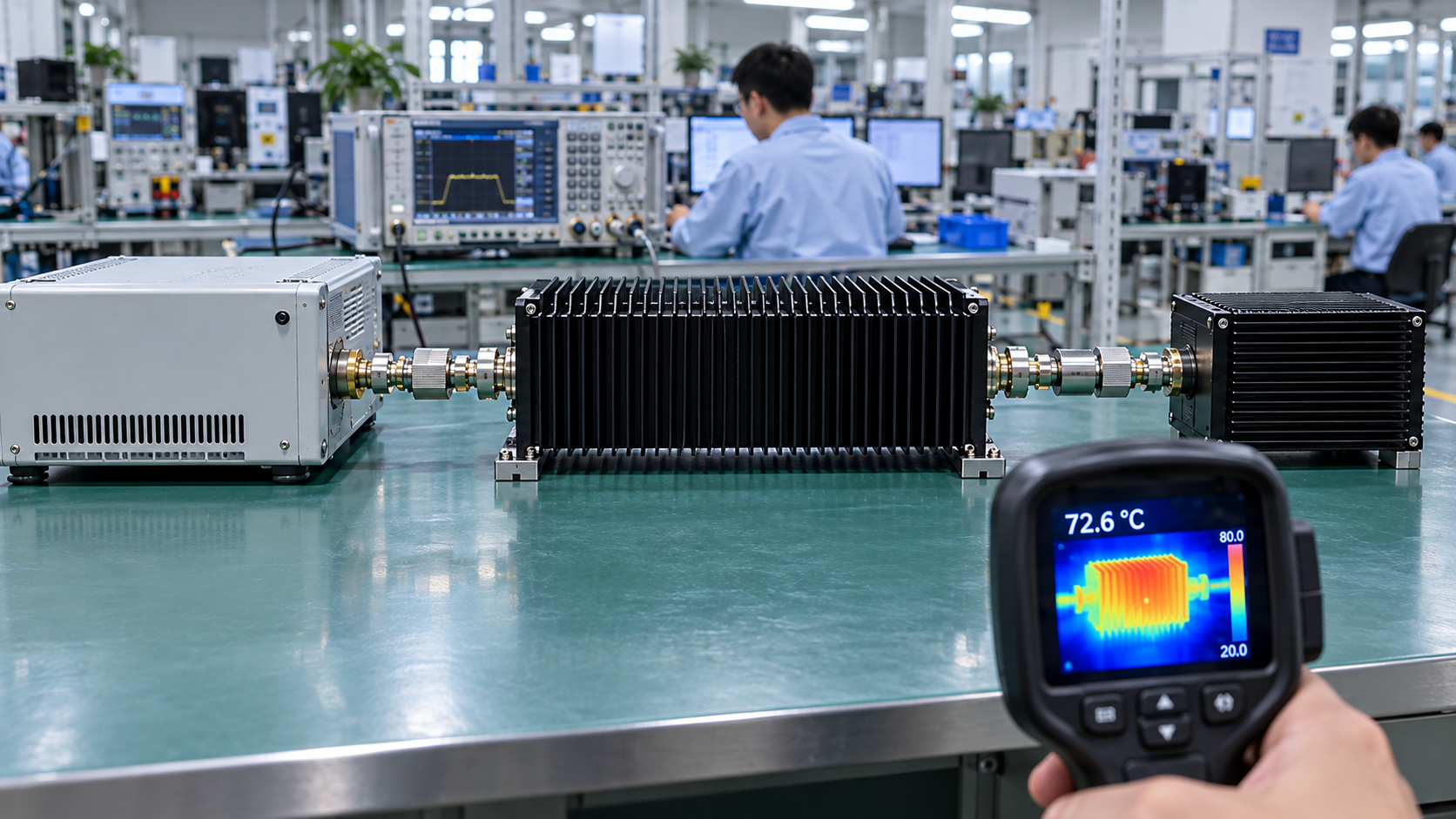
RF attenuator power rating matters in RF PA testing because an underrated attenuator can overheat, compromise measurement accuracy, or damage the test chain. But the wattage printed on the device cannot establish whether it is suitable for a particular test. That depends on the actual RF power reaching the attenuator and the conditions under which its rating applies.
When testing RF Power Amplifier Modules, the attenuator’s actual input power matters more than the PA’s nameplate wattage. Waveform, frequency, operating duration, cooling, and connector conditions also affect whether the published rating applies.
The first check is straightforward: where does the attenuator sit in the RF path, and how much power reaches it?
1. Where Does an Attenuator Sit in the RF PA Test Chain?
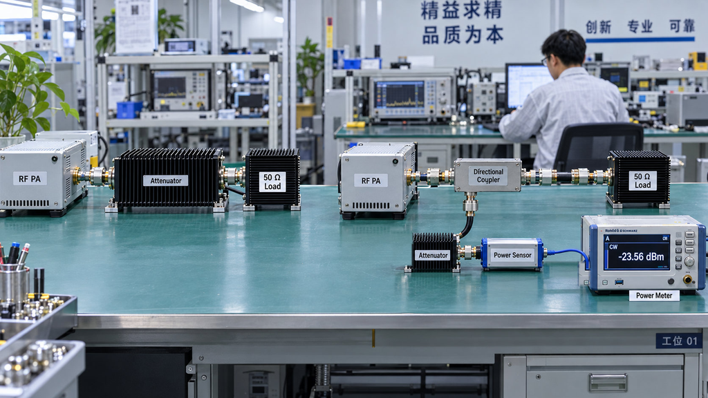
An attenuator connected directly to the PA output faces a different power requirement from one connected to a directional coupler’s sampling port.
In a direct measurement path, the attenuator may receive nearly all the PA’s forward output power. If the amplifier delivers 100 W into a matched path, the attenuator must handle that input under the specified waveform, frequency, duration, and cooling conditions. Reducing the signal to a level suitable for the power sensor does not reduce the power entering the attenuator.
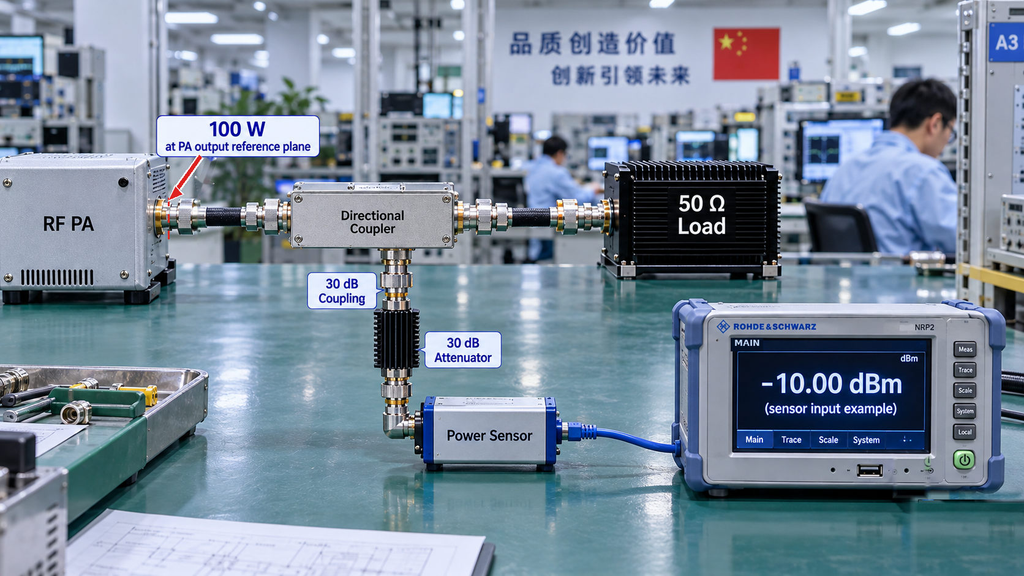
A directional coupler allows the measurement system to sample the signal without routing the main RF power through the sampling attenuator. A typical controlled test arrangement is:
PA → Directional Coupler → 50 Ω Dummy Load
The forward-coupled port feeds a power sensor, with an additional attenuator inserted if the sampled signal exceeds the sensor’s permitted input range.
For example, if 100 W of forward power reaches a directional coupler with a nominal 30 dB coupling factor, the forward-coupled port provides approximately 0.1 W under ideal matched conditions. That is the sampled power before any additional attenuation. The main RF path continues toward the dummy load.
Actual coupled power depends on the coupler’s frequency-dependent characteristics, port termination, and operating conditions. The nominal coupling factor alone is not a complete measurement correction.
These arrangements place very different demands on the attenuator. In the direct path, a high-power unit may need to dissipate nearly the full PA output. In the sampling path, the attenuator normally handles a much smaller signal determined by the coupler and the actual port conditions.
Before choosing an attenuator, identify its input and output ports, intended power-flow direction, maximum expected input power, and measurement reference plane. If the power at that point cannot be established or conservatively bounded, the device is not yet qualified for the test.
The complete measurement sequence is covered by the full-power RF PA test procedure. Here, the immediate task is to establish the load placed on the attenuator itself.
2. Why Can a 30 dB Attenuator Still Overheat at 100 W?
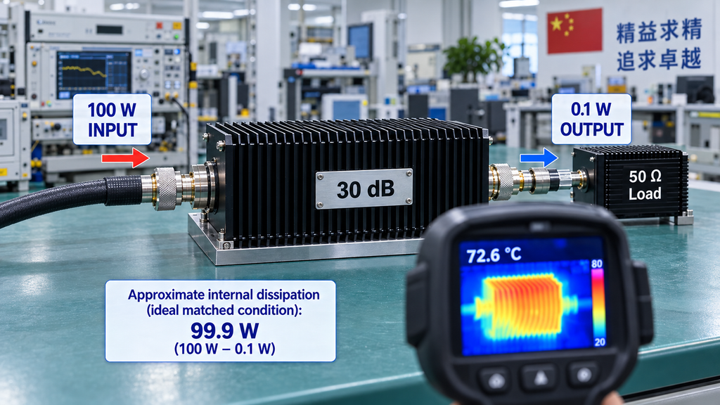
A high attenuation value says little about how much heat the attenuator can safely dissipate.
Attenuation, expressed in decibels (dB), describes the reduction in transmitted signal power. Power handling describes the RF power a device can withstand under its specified operating conditions. The two specifications serve different purposes.
Consider a 30 dB attenuator connected between a 100 W RF source and a properly matched load.
Under ideal matched conditions, the transmitted output power is:
Pout = Pin × 10^(-A/10)
Here, Pin is the input power delivered into the attenuator, Pout is the power delivered to the load, and A is the attenuation in dB.
For 100 W input and 30 dB attenuation:
Pout = 100 × 10^(-30/10) = 0.1 W
The approximate internal dissipation is:
Pdiss = 100 - 0.1 = 99.9 W
Almost the entire 100 W becomes heat inside the attenuator, even though the transmitted output is only 100 mW.
This calculation assumes matched ports and ignores additional losses outside the attenuator. In an actual test, reflected power and the power delivered at each port affect the internal dissipation. The calculated 99.9 W is an illustration of the energy balance, not a manufacturer-approved operating limit.
The rating definition also needs attention. A manufacturer may specify maximum input power, continuous average power, peak power, or a rating tied to particular thermal conditions. An internal heat-dissipation estimate cannot be compared blindly with a number whose definition is different.
A small 30 dB attenuator rated for only a few watts of continuous input could fail under 100 W excitation. A high-power design may handle that exposure if the applicable rating and cooling conditions support it.
Calculate the expected power entering and dissipated by the attenuator, then compare those values with the manufacturer’s actual rating definitions. The dB value alone cannot settle the question.
3. How to Compare CW, Average, and Peak Power Ratings
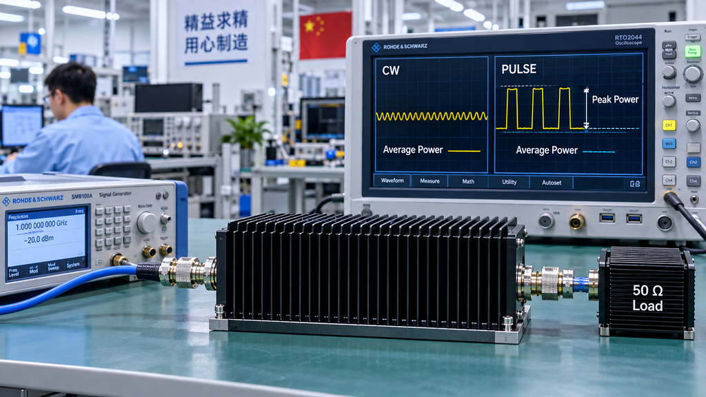
An attenuator rated for hundreds of watts of peak power may be unsuitable for a much lower continuous-wave test. The difference comes from how the power is applied and how the manufacturer defines the rating.
Continuous-wave (CW) operation applies RF power continuously at a defined level. For a steady CW signal, average power remains approximately constant over the relevant interval. Sustained PA testing therefore places particular importance on the applicable continuous or average-power limit.
Pulsed operation introduces another set of conditions. Average power depends on the waveform, pulse duration, repetition rate, and duty cycle. Peak power describes the highest applicable instantaneous or pulse-related level under the manufacturer’s definition. Lower average power may reduce thermal loading, but a pulse can still exceed the device’s permitted peak-power or pulse-energy limits.
The Keysight 8498A high-power attenuator illustrates the distinction. Its published specifications list a maximum average input power of 25 W, alongside peak input-power limits of 500 W from DC to 5.8 GHz and 125 W above 5.8 GHz through 18 GHz.
The 500 W figure is not permission to operate continuously at 500 W. The applicable pulse restrictions, frequency range, and other operating conditions still govern whether a particular test is allowed.
For CW testing, compare the expected input against the specified continuous or average-power capability. For pulsed testing, check both average loading and the relevant peak-power, pulse-width, and duty-cycle restrictions. A device that satisfies one limit may still exceed another.
Two attenuators cannot be ranked meaningfully by their largest published wattage unless the power definition, waveform, frequency, duration, and cooling conditions are comparable.
If the manufacturer’s data do not cover the proposed waveform or test duration, obtain the missing specification rather than calculating an unsupported rating from duty cycle alone.
4. How to Check Frequency, VSWR, and Connector Limits
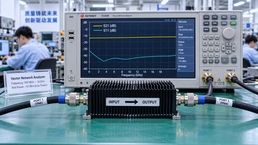
An attenuator’s operating frequency range does not guarantee constant attenuation accuracy, matching performance, or power-handling capability across the entire band.
A nominal 30 dB attenuator may have different actual attenuation values at different frequencies. Those differences affect the power reaching the sensor and the correction used to calculate PA output. A component that meets the required attenuation at one frequency may not meet the same measurement requirement at another.
Voltage standing-wave ratio (VSWR) also matters. In a nominal 50 Ω test system, imperfect matching can create reflections and measurement uncertainty. Review the manufacturer’s input and output matching specifications at the intended frequencies, together with the source and load conditions. A favorable low-power VSWR measurement does not establish high-power thermal capability.
High-power operation introduces an additional concern: signal direction.
Some high-power attenuators are thermally rated for one direction only. The Bird 500-WA series, for example, specifies a unidirectional average-power rating. Reversing such a device may still produce attenuation at low power, but its published forward-power capacity cannot be assumed to apply in reverse.
Respect the designated input and output ports. If significant reflected power could reach the attenuator, check its applicable reverse-power and mismatch limits. This is particularly important when the downstream termination or RF connection may produce substantial reflections.
Connectors and adapters can impose their own restrictions. Poor contact, damaged interfaces, unsuitable adapters, or excessive mismatch may cause local heating even when the attenuator’s internal power-handling specification appears adequate.
The dummy load needs a separate assessment. Its power rating and matching requirements determine whether it can safely absorb the RF power delivered to it. A qualified load does not establish the suitability of an upstream attenuator.
For swept-frequency testing, verify the relevant attenuation, VSWR, connector, power-direction, and power-rating conditions across the intended range. A single-frequency result cannot qualify the entire band.
5. How to Check Cooling and Hot-State Attenuation Drift
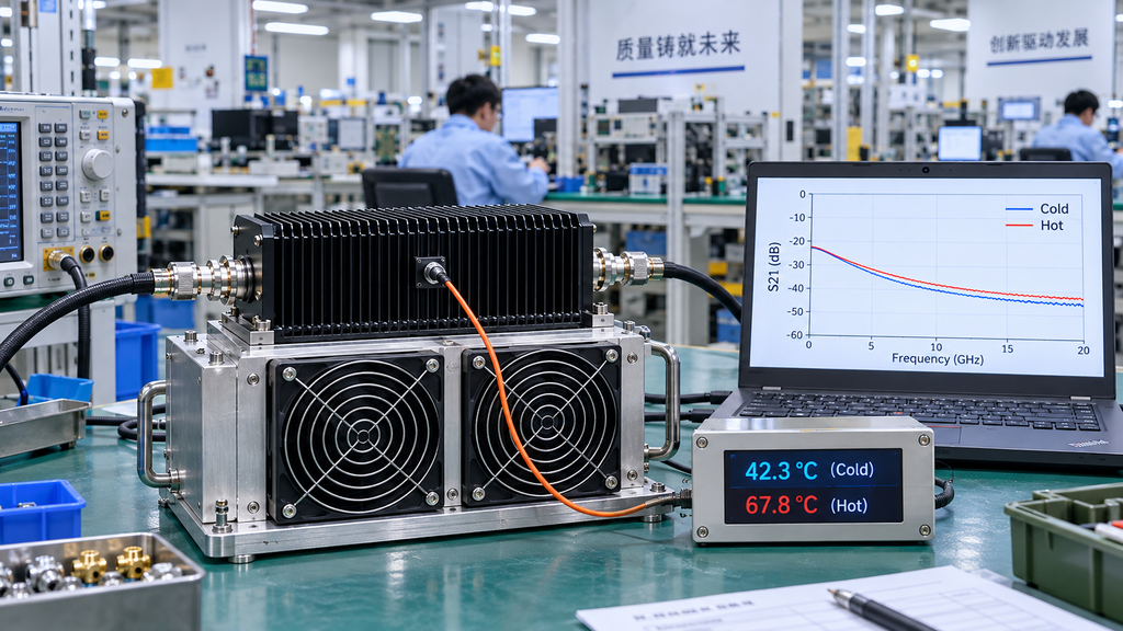
The published power rating may assume a specific mounting surface, ambient temperature, airflow, or heat-dissipation arrangement. Those conditions matter when the attenuator is installed in a real test cabinet.
Some high-power designs require direct contact with a suitable heatsink. Others specify forced-air cooling or a temperature-dependent reduction in permitted input power. A rating established under controlled cooling cannot be carried over unchanged to an installation with restricted airflow or a different thermal interface.
A short test can also give a misleading impression. The attenuator may behave normally during the first minutes of RF exposure while heat continues to accumulate. A sustained PA test requires the applicable rating to cover the intended duration and thermal condition.
Temperature can change attenuation characteristics, although the amount and direction of the change depend on the particular device. That affects measurement accuracy as well as component performance.
Suppose the measured PA output appears to drift during a long test. If the power calculation uses a cold-state attenuation value while the attenuator’s actual loss changes as it heats, part of the apparent drift may come from the measurement path. Without relevant thermal data, the change cannot be attributed confidently to the PA.
Where hot-state accuracy matters, use applicable manufacturer data or measurements taken under defined thermal conditions. Compare cold and hot results at consistent frequencies, power levels, connections, and reference planes.
The engineer needs evidence that the attenuator can withstand the required exposure and maintain the measurement performance the test demands. These may require different forms of verification.
If the specified cooling cannot be provided, or the required operating temperature falls outside the supported conditions, the room-temperature wattage rating is insufficient to approve the test.
6. How to Protect the Sensor Without Misreading PA Output
An adequately rated attenuator can still deliver too much RF power to the measurement sensor.
Return to the direct-path example: 100 W entering a 30 dB attenuator produces approximately 0.1 W at the output under ideal matched conditions. That is 100 mW, or +20 dBm.
Whether +20 dBm is safe depends on the specific power sensor and its applicable input limits. The attenuator’s ability to handle 100 W says nothing about the sensor’s ability to accept its output.
A coupled measurement path has different numbers. With 100 W of forward power and a nominal 30 dB coupling factor, the coupler provides approximately 0.1 W at the forward-coupled port under the stated matched conditions. Adding a separate 30 dB attenuator to that sampling path reduces the idealized signal to approximately 0.1 mW, or -10 dBm, before other path losses.
The coupler and attenuator both reduce the signal reaching the sensor, but they do so at different locations. The main RF power remains on the path to the dummy load, while the attenuator in the coupled branch handles the sampled power.
In both arrangements, calculate the expected sensor input and compare it with the sensor’s applicable average and peak-power limits. Include the real coupling and attenuation characteristics where they affect the result.
Safe sensor input is only part of the measurement requirement. The raw power-meter reading represents the power at the sensor input, not necessarily the power at the PA output connector.
To report PA output, the measurement system must account for the relevant coupling, attenuation, cable losses, and reference planes. Nominal dB values may not represent the actual loss at every frequency or temperature. Applying them without checking the measurement path can distort the corrected output value.
The detailed method belongs to test cable loss compensation in RF PA acceptance. For this qualification, establish two things: the sensor can safely handle the signal, and the measurement-path data are sufficient for the intended PA output calculation.
If the sensor input limit is unknown, the setup is not yet qualified for RF exposure. If the sensor is safe but the correction data are incomplete, the measurement may be electrically safe without producing a qualified PA output result.
7. What Evidence Qualifies an Attenuator for RF PA Testing?
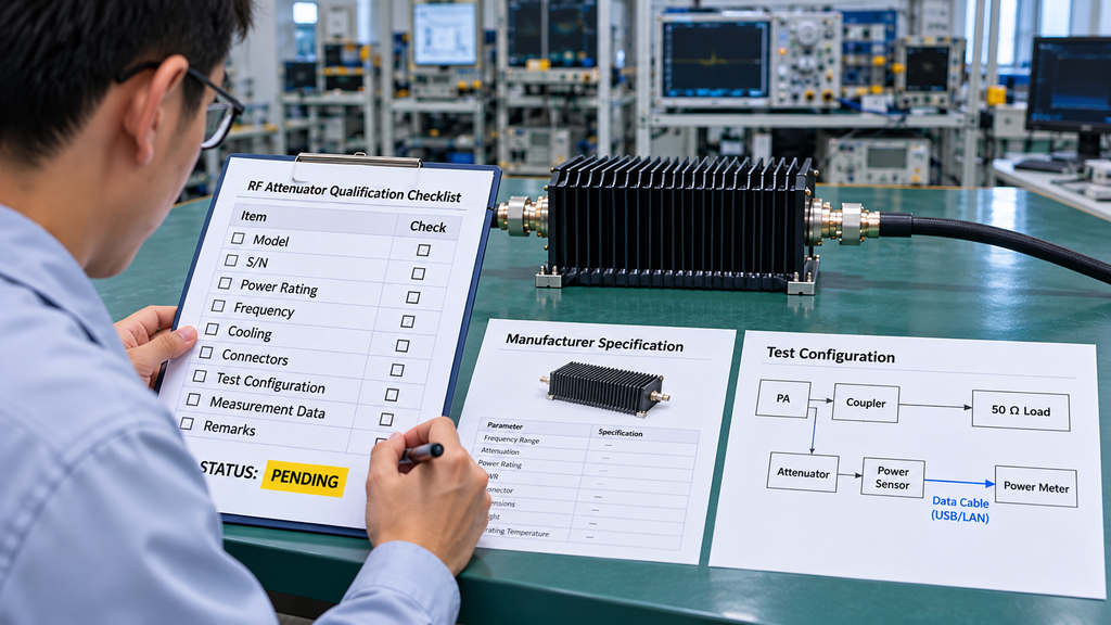
An attenuator is suitable for a test when its documented capabilities cover the actual operating conditions. The qualification must refer to the component’s position in the RF path and the conditions under which it will be used.
A useful record connects the expected input power and waveform to the manufacturer’s applicable ratings, then checks frequency, attenuation, matching, power-flow direction, cooling, and downstream sensor limits.
The following matrix keeps those requirements together without treating a missing specification as proof of equipment failure.
| Qualification item | Actual test requirement | Required rating or evidence | Decision result |
|---|---|---|---|
| Installation position | Main path or coupled sample path; actual input power and power-flow direction | RF connection arrangement, input/output designation, coupling information, and applicable directional power limits | Qualified / Pending / Unsuitable |
| Power handling | CW, average, and peak input power under the specified waveform | Manufacturer power-rating definitions, operating restrictions, and relevant dissipation conditions | Qualified / Pending / Unsuitable |
| Frequency coverage | Operating frequencies or swept-frequency range | Frequency coverage and applicable frequency-dependent power limits | Qualified / Pending / Unsuitable |
| Attenuation and matching | Required attenuation accuracy, input/output VSWR, and expected reverse-power conditions | Frequency-dependent attenuation data, matching specifications, and reverse-power or mismatch limits | Qualified / Pending / Unsuitable |
| Thermal loading | Cooling arrangement, ambient temperature, mounting, and operating duration | Cooling requirements, temperature limits, and applicable derating or hot-state data | Qualified / Pending / Unsuitable |
| Sensor safety | Maximum expected average and peak power at the sensor input | Measurement-path attenuation, sensor input ratings, and power-correction basis | Qualified / Pending / Unsuitable |
| Equipment traceability | Identifiable attenuator and test configuration | Manufacturer, model, applicable specification revision, and relevant equipment records | Evidence complete / Missing |
Use Qualified when applicable specifications and any required verification support the intended test. Use Unsuitable when a known operating limit is exceeded. Use Pending when a critical condition has not been established.
For example, a directional attenuator might meet the required forward input-power rating but lack evidence for the expected reflected-power conditions. Another unit might cover the full frequency range yet require a heatsink that the laboratory installation cannot accommodate. The first case needs further evidence; the second may require a different installation or component.
There is no single safety margin that can be applied to every attenuator without a defined engineering basis. Nor does qualification at one frequency or temperature establish suitability for every operating condition.
The record should identify the attenuator, the applicable specification revision, and the actual test configuration. If project requirements call for measured hot-state performance, the evidence must correspond to the relevant equipment and operating conditions.
Once the requirements are checked, the engineer can approve the attenuator for the defined setup, identify a necessary configuration change, or hold the test pending additional evidence.
This approval concerns the attenuator and its role in the measurement path. The RF PA and complete test system still require their own acceptance evidence.
Conclusion
RF attenuator power rating matters because the device must handle the actual RF input and resulting heat load without compromising measurement accuracy. Its advertised wattage is sufficient only when the manufacturer’s defined conditions match the intended test.
A valid qualification must account for waveform, frequency, operating duration, cooling, connector conditions, permitted power-flow direction, and downstream sensor limits. Peak-power capacity does not establish continuous-power capacity, and a large attenuation value may still leave the device dissipating substantial heat.
Before applying full RF power, document the attenuator’s position, expected input power, applicable limits, cooling arrangement, and sensor input requirements. Complete the qualification matrix and resolve any unsupported conditions. The final suitability decision must rest on evidence for the specific device and test configuration.
For RF PA projects that need engineering review, RF SKYPOWER can assess the amplifier requirements against the proposed operating and test conditions. Provide the frequency range, required PA output power and reference plane, waveform, CW or pulse conditions, duty cycle where applicable, test duration, RF load, measurement arrangement, cooling conditions, sensor input limits, and required test evidence.
Contact RF SKYPOWER to discuss your RF PA project requirements.