










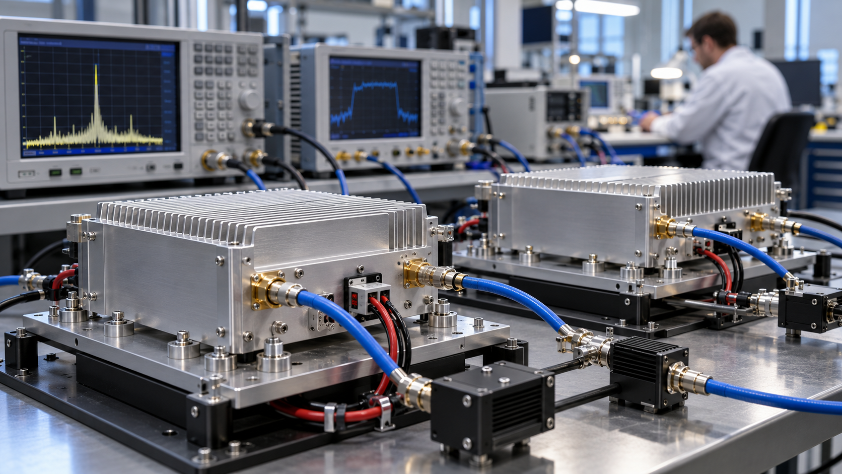
Two RF power amplifiers can deliver the same output power while drawing different DC currents. RF PA current spread reveals these differences across a production batch, but the results are only comparable when frequency, waveform, actual output power, supply voltage, load, temperature, and measurement methods are controlled.
For a batch of RF power amplifier modules, higher current may indicate greater DC power demand. It may also result from differences in RF drive, bias, temperature, or test conditions. The reading alone cannot establish a manufacturing defect or acceptance failure.
A useful comparison starts with matched operating conditions, followed by repeatability checks and an assessment of whether the observed differences warrant engineering investigation.
1. What Does RF PA Current Spread Actually Reveal?
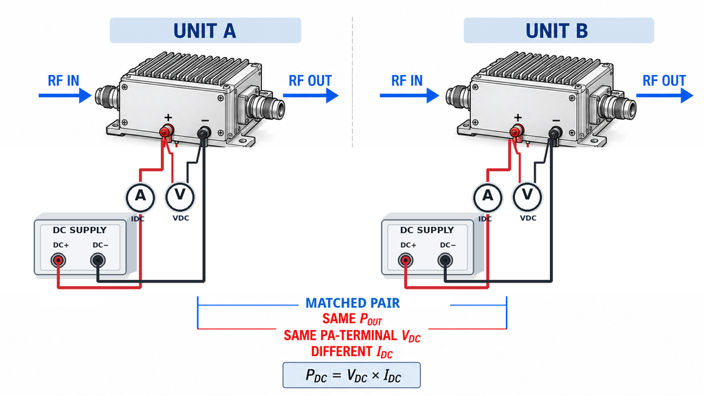
A batch comparison of RF amplifier current consumption shows how much DC current individual modules draw at a defined RF operating point. It can reveal differences in electrical demand that output-power measurements alone would miss.
Pout measures RF power at a specified output reference plane. IDC measures current through a particular DC supply path.
For a module operating from one stable DC supply:
PDC = VDC × IDC
Here, VDC is the voltage measured at the module’s DC input terminals, and IDC is the corresponding supply current.
If two amplifiers deliver the same Pout at essentially the same VDC, the unit drawing more current also consumes more DC input power at that supply boundary. This may affect power-supply loading, cooling requirements, or unit-to-unit consistency.
The cause of the difference requires further investigation.
During a matched-output test, one amplifier may need more RF input power than another to reach the target Pout. Gain, compression behavior, bias, and auxiliary circuitry can all affect DC demand.
A higher IDC reading therefore does not independently establish lower transistor efficiency. Power-added efficiency (PAE) requires RF input power, RF output power, and DC input power to be measured at the appropriate boundaries.
Multiple Supply Rails and Dynamic Power
For a module with several stable DC supply rails, calculate total input power by summing the power from each rail:
PDC,total = Σ(Vi × Ii)
Adding currents from rails operating at different voltages does not produce a valid total-power figure.
When voltage and current vary significantly over time, average DC input power is:
PDC,avg = average[V(t) × I(t)]
The averaging interval must be defined. Multiplying independently averaged voltage and current readings does not necessarily produce the same result when both waveforms vary.
For stable supply conditions, average voltage multiplied by average current may be a suitable approximation. Pulsed operation with substantial ripple or transients requires a measurement method that captures the relevant waveform behavior. For multiple dynamic rails, account for each rail’s power contribution over the defined interval.
These measurements characterize module-level electrical demand under specified conditions. Identifying its internal causes requires additional evidence.
2. What Must Match Before Comparing DC Current?
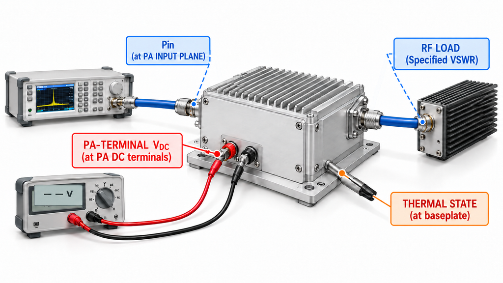
Identical part numbers and nominal output-power settings do not guarantee comparable current measurements.
Before collecting batch data, define five operating boundaries:
- Product configuration: Hardware revision, bias configuration, control settings, firmware where applicable, and operating mode.
- RF operating point: Frequency, waveform, duty cycle, output-power definition, target Pout, permitted tolerance, and output reference plane.
- RF drive and load: Actual Pin at the PA input reference plane, load conditions, VSWR, and measurement corrections.
- DC supply conditions: Actual module-terminal VDC, the measured supply rail, and relevant current-limiting behavior.
- Thermal conditions: Cooling arrangement, controlled temperature, measurement location, and stabilization criteria.
Changes in these conditions can affect IDC without indicating a difference in manufacturing quality.
Match RF Power Definitions
CW and pulsed measurements require different power definitions.
For pulsed tests, RF power amplifier duty cycle, repetition behavior, and power measurement basis must be consistent. Peak pulse power, average power over a complete pulse period, and average power within a selected pulse interval cannot be used interchangeably.
Two amplifiers may produce similar peak RF power at different duty cycles while drawing substantially different average DC currents.
The DC measurement window must correspond to the chosen RF operating condition. If average current is measured over several pulse periods, record the averaging interval. If current during a selected pulse interval is required, verify that the instrument has sufficient bandwidth and response time.
Match Actual Voltage and Temperature
The voltage displayed by a power supply may differ from the voltage reaching the PA.
Supply cables, connectors, and fixtures introduce resistance. Their voltage drop changes with current, so VDC should be measured at the defined module terminals.
Temperature requires equal care. A common ambient temperature does not guarantee identical baseplate, case, or junction temperature.
Specify the controlled temperature, measurement location, and stabilization criterion before testing. The criterion might define an allowable change in monitored temperature or an electrical reading over a specified interval.
Check Residual Operating-Point Differences
Even when every amplifier meets the Pout tolerance, actual output levels may differ.
This matters because IDC can change with Pout, particularly near compression. A unit operating near the upper end of the permitted output range may draw more current partly because it delivers more RF power.
Residual differences in VDC and temperature can produce similar effects.
Before classifying a current reading as abnormal, assess whether the remaining variations could materially change the comparison.
Where needed, characterize a representative amplifier at nearby permitted operating points to observe how IDC responds to changes in Pout, VDC, or temperature.
Keep these sensitivity measurements within safe operating limits. Results from one configuration cannot automatically be applied to every hardware revision or unit.
If residual differences could affect the judgment, tighten the test conditions or investigate their effects separately. Do not mathematically correct IDC without a validated relationship and associated uncertainty.
The measurements can then be classified:
Comparable: Relevant conditions are aligned, and remaining differences are sufficiently controlled.
Partially comparable: Some conditions differ, but valid subgroups or additional sensitivity evidence allow a limited comparison.
Not comparable yet: Important conditions, reference planes, or operating-point effects remain unresolved.
Measurements in the last category should not be used to rank amplifiers or identify production outliers.
3. How to Measure Idc at Matched RF Output
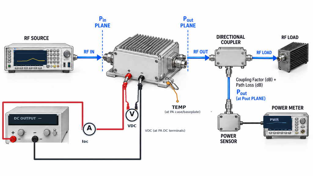
A matched-output test measures the DC current each amplifier draws while delivering the same specified RF output under equivalent conditions.
It differs from a fixed-input test.
With fixed Pin, every amplifier receives the same actual RF drive, so gain differences may produce different Pout values.
With matched Pout, the drive is adjusted within the permitted operating range to reach the required output.
For current-spread testing, matched Pout is the primary comparison condition. Actual Pin must also be recorded because the drive required to reach that output may differ between units.
Because Pin is adjusted to reach the same Pout, matched-output current measurements cannot establish batch gain tolerance under fixed-input conditions.
Establish the RF Operating Point
Define the RF output reference plane, normally at the specified PA output connector or another agreed point.
Use an appropriately rated load and measurement path. Apply verified corrections for attenuation, coupling factors, and relevant path losses so reported Pout refers to the correct plane.
Set the target Pout and permitted deviation before testing.
For each amplifier, record the RF amplifier input drive level as actual Pin at the PA input reference plane, or determine it through a verified correction to that plane.
Adjust the drive only within the permitted test method and operating limits. Never bypass protection functions or exceed specified operating conditions to force a unit to reach the target power.
If a unit cannot reach the required Pout under valid conditions, record that result separately. It does not belong in the matched-output current population.
Retain actual Pout for every tested unit. Check whether remaining differences in output, terminal voltage, or temperature could explain a meaningful portion of the observed IDC variation.
For frequency-dependent testing, repeat the measurements at each specified frequency and keep the results separated by test point.
Measure Current at the Module DC Input
Measure current in the DC supply path corresponding to the defined module boundary.
A calibrated inline current transducer or suitable shunt-based arrangement can be used if its current range, bandwidth, accuracy, and installation effects satisfy the test requirements.
The measurement device must not introduce enough voltage drop to materially change the operating point.
For shunt measurements, consider resistance, connections, temperature effects, and instrument accuracy. Four-terminal sensing can reduce errors caused by lead resistance where appropriate.
Measure VDC at the specified module terminals. Separate voltage-sense connections or suitable remote sensing can distinguish actual terminal voltage from the power supply’s displayed value.
Identify the measured supply rail. For multi-rail modules, record each relevant rail separately rather than treating one rail’s current as total module current.
Confirm that the amplifier remains in its intended operating mode. Current limiting, thermal protection, RF faults, or changes in control state can make a reading unsuitable for comparison.
Synchronize RF, DC, and Thermal Measurements
RF power, DC voltage, current, and temperature must describe the same operating state.
For stable CW operation, collect the measurements after the defined stabilization criteria have been met.
For pulsed or dynamic operation, specify the acquisition interval and averaging method for each quantity.
A slow current instrument may provide a useful average without resolving individual pulse peaks. Its response and sampling method must match the quantity being measured.
When RF and DC instruments use different acquisition methods, verify that their results represent equivalent operating intervals.
Keep startup, transient, and stabilized operating-current measurements separately identified.
Record Each Tested Unit
The result should be traceable to the measured unit and operating point.
The common test record must identify the batch, hardware revision, test-point ID, frequency, waveform, duty cycle, target Pout, RF reference planes, load, DC rail, cooling configuration, stabilization criteria, instruments, measurement corrections, and test-method revision.
Use the following structure for unit-level results.
| Unit S/N | Measured Pout (W) | Actual Pin (dBm) | PA-terminal VDC (V) | PA-terminal IDC (A) | Temperature (°C and measurement point) | Retest / disposition |
|---|---|---|---|---|---|---|
| Enter S/N | — | — | — | — | — | Not evaluated |
| Enter S/N | — | — | — | — | — | Not evaluated |
Blank measurement template. No RF SKYPOWER batch test results are represented.
Each completed table must reference its common test point, including frequency, target output, waveform, thermal state, and test-method revision.
When the same S/N is measured at multiple frequencies or operating states, maintain separate records. Do not merge those readings into one current distribution without a defined comparison method.
Specify whether RF power and DC current represent CW, average, or pulse-related quantities. For multi-rail modules, retain the corresponding rail measurements.
Keep original readings and retests traceable. A later result should not silently replace an earlier observation.
4. How to Separate Test Variation from Batch Spread
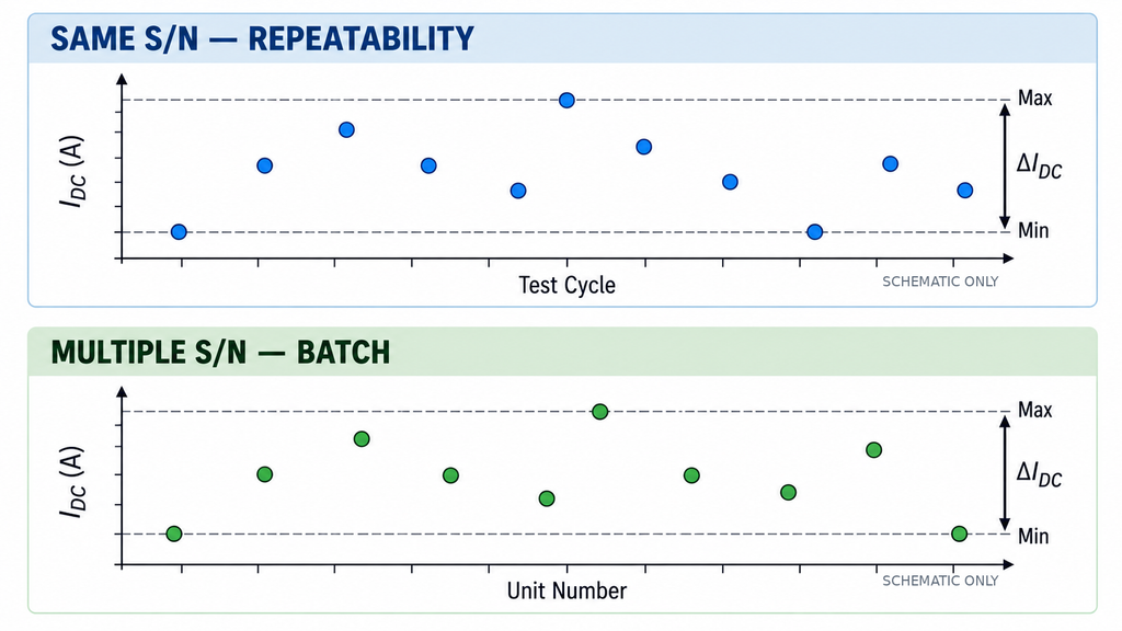
Different IDC readings can result from module variation, measurement variation, or both.
To distinguish them, measure how much the result changes when the same amplifier is tested repeatedly, then compare that variation with the differences observed between units.
Within-unit variation describes changes in current readings when one amplifier is measured repeatedly under controlled conditions.
Between-unit variation describes differences among amplifiers in the comparison group.
Between-unit variation includes possible measurement effects and residual operating-point differences. Identifying manufacturing variation requires sufficient evidence to distinguish these contributions.
Establish Measurement Repeatability
Begin with repeated measurements of an appropriate reference unit.
Keep the operating conditions, measurement arrangement, and environment consistent. Choose the number of repetitions before examining batch results, based on the measurement capability the project needs.
Record IDC together with Pout, Pin, VDC, and temperature for each repetition. Use an appropriate measure of dispersion, such as standard deviation or range, to describe the variation.
Every repetition should have a traceable run record identifying the test station, relevant instrument configuration, whether the module was reconnected, whether the RF operating point was re-established, and whether the fixture changed.
Link retests to the original S/N, test point, and measurement records.
These details distinguish short-term repeatability from variation introduced by reconnecting equipment or using another station.
Stable readings taken without disturbing the setup do not establish that the same result will be obtained after fixture replacement, operator changes, or testing on another station.
Include these effects when they are part of normal production testing. Additional reference units may also be needed if measurement variation changes across operating-current or temperature ranges.
Determine Whether the System Can Resolve the Required Difference
Before classifying outliers, define the smallest current difference that matters to the engineering decision.
It may relate to DC supply margin, thermal loading, or a reason to investigate a production subgroup. This is a measurement objective, not automatically a product acceptance limit.
Assess whether the measurement system can resolve that difference with sufficient confidence.
Relevant factors include repeatability, instrument resolution, calibration uncertainty, fixture and station effects, and residual changes in Pout, VDC, or temperature.
The uncertainty of a difference between two measurements is not necessarily the sum of their individual uncertainties. Shared systematic effects may be correlated, while independent errors contribute differently.
Use an uncertainty analysis or measurement-system study suited to the test and intended decision.
For example, if repeated measurements of one amplifier vary by an amount similar to the differences observed among several units, the data may not reliably distinguish those units.
Investigate the measurement variation before classifying the amplifiers as abnormal. Testing more units does not necessarily correct systematic error or poor reproducibility.
Interpret the Batch Distribution
Once measurement capability is established, examine the current distribution within each valid comparison group.
A basic measure is:
IDC spread = IDC,max − IDC,min
This gives the difference between the highest and lowest observed currents.
Range is easy to calculate, but it depends on sample size and extreme observations. A larger sample may reveal a wider range even when the underlying process has not changed.
Median, standard deviation, distribution shape, and other statistics can provide additional context when supported by the sampling plan.
The appropriate statistic depends on the question. One unusually high-current unit requires a different investigation from a gradual shift across successive production lots.
Even when measured differences are distinguishable from test variation, the results describe the tested population. They do not establish the distribution of untested units or future batches.
Estimating manufacturing variation separately from measurement variation may require a statistical model designed for that purpose. Arbitrarily subtracting the repeatability range from the observed batch range is not valid.
Check for Test-Station and Production Subgroups
Examine whether unusual readings follow a test station, hardware revision, production lot, or measurement sequence.
If higher currents appear mainly at one station, check its current measurement, RF corrections, terminal voltage, and thermal conditions.
If the pattern follows a hardware revision or production lot, retain that subgroup identity and review the associated records.
Reference-unit checks across sessions, repeated setup cycles, and controlled changes in test order can help identify station effects or time-dependent drift.
The investigation depth should match the decision. A preliminary comparison may need controlled repeat measurements, while formal production acceptance may require a broader measurement-system study.
If the available evidence cannot distinguish measurement variation from unit differences, the batch difference has not yet been established.
5. What Can a High-Current Outlier Tell You?
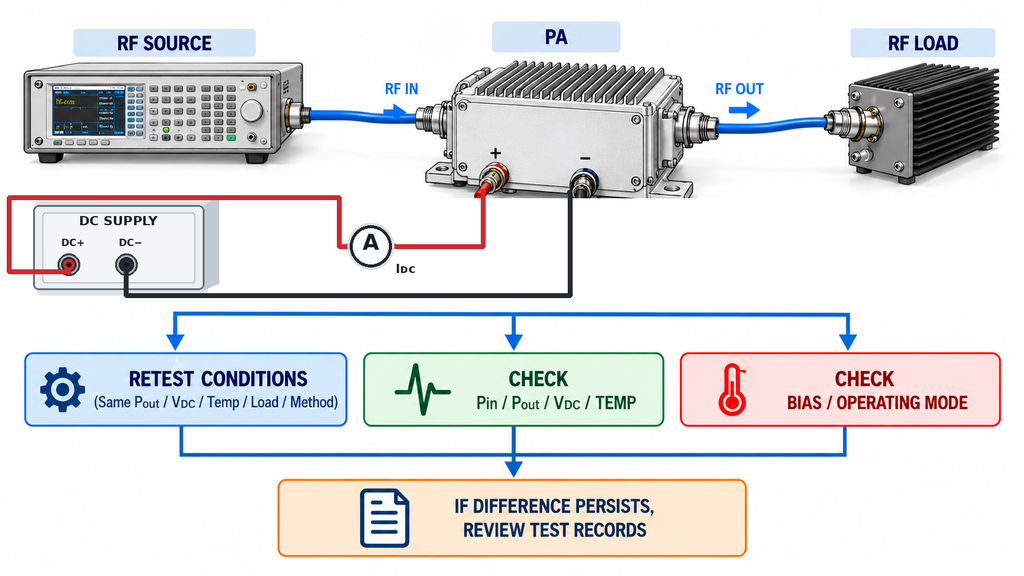
A high-current outlier warrants further examination but does not identify a specific internal fault.
Start by repeating the measurement under the established conditions. Check actual Pout, Pin, module-terminal VDC, temperature, load, and operating mode.
If the difference disappears after correcting a measurement condition or restoring the required thermal state, investigate the test process before attributing the original reading to the amplifier.
If the difference persists, check the RF input power required to reach the target Pout.
An amplifier operating at a different gain or compression point may draw a different current. Review bias settings, quiescent conditions, load behavior, control state, and auxiliary circuitry before drawing conclusions about internal hardware.
Hardware revision, component variation, assembly history, and rework records become relevant when the evidence points toward a production-related difference.
If higher current consistently appears in units sharing a hardware revision, component lot, or rework history, investigate whether RF PA process changes contributed to the difference.
The next action should address a specific unresolved question, such as repeating the measurement under tighter conditions, examining bias records, or comparing production subgroups.
If the investigation does not establish a cause, document the repeatable difference and the evidence still required.
6. How to Set Review Triggers for Current Spread
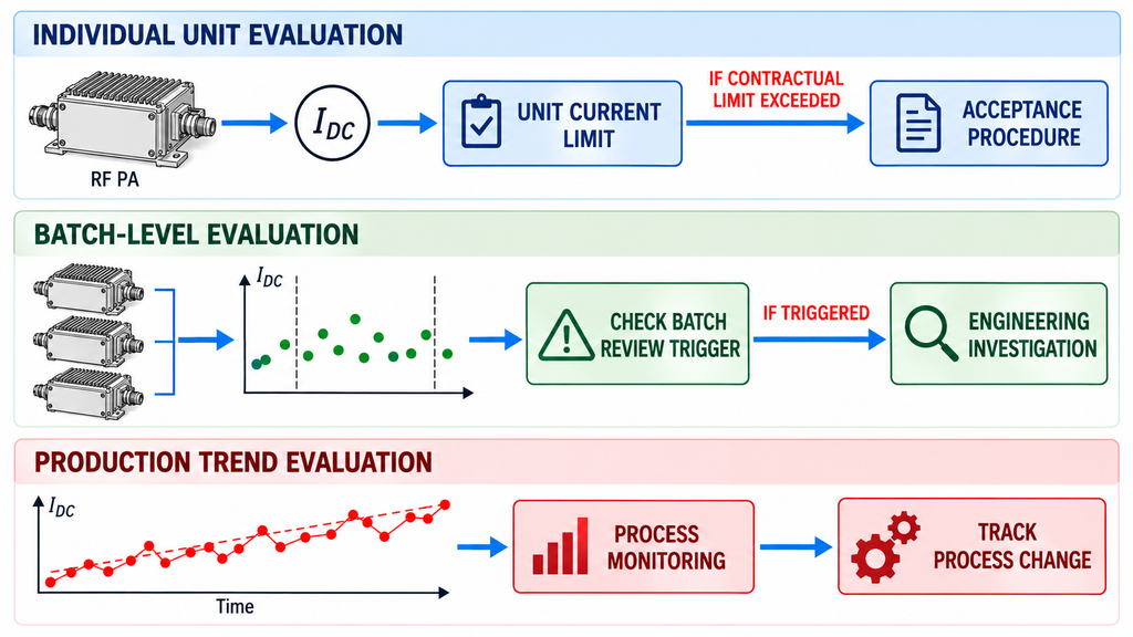
A current-spread review trigger defines when a measurement requires engineering attention.
Its purpose, operating conditions, reference data, and required action should be agreed before the batch is tested.
Three boundaries serve different purposes.
An individual-unit current limit defines an electrical requirement applicable to a unit under specified conditions.
A batch review trigger identifies a unit deviation or distribution pattern that requires investigation.
A process-monitoring boundary tracks manufacturing behavior. It does not automatically establish a contractual product limit.
Build the Review Trigger from a Valid Reference
Start with suitable reference measurements collected under comparable conditions.
Identify the model, hardware revision, RF operating point, test method, and production population. Check measurement capability and whether the reference process was sufficiently stable for the intended analysis.
Avoid combining incompatible revisions or test conditions merely to enlarge the reference sample.
Next, define the change the rule should detect.
A single high-current unit, a shift in typical batch current, and an increase in batch spread are different problems. Each may require a different statistic and response.
A unit-level trigger might examine deviation from a qualified reference population. A batch-level trigger might monitor changes in distribution center or spread across production lots.
Statistical process-control limits require an appropriate baseline. Depending on the method, this may involve observations in production order, a defined sampling scheme, or rational subgroups.
Assess process stability and the method’s assumptions before treating those limits as established monitoring boundaries. One batch’s highest and lowest values cannot establish reliable long-term process-control limits.
Where historical evidence is insufficient, a provisional engineering investigation trigger may still be appropriate. Document its rationale and obtain the required approval, without presenting it as a validated statistical control limit or contractual acceptance criterion.
The measurement system must be capable of resolving the difference the trigger is intended to detect.
Finally, connect the rule to the engineering consequence. A current increase affecting supply margin or thermal loading may justify investigation, while a smaller change without demonstrated significance may not.
Write an Actionable Review Rule
An actionable rule identifies the test point, approved boundary, measurement validity requirements, triggering condition, and response.
For example:
At each approved RF test point, a unit with a valid measured current outside the approved current-review boundary shall undergo the specified repeat measurement and documented engineering investigation. This trigger does not constitute an automatic contractual failure unless the applicable acceptance agreement explicitly defines that consequence.
This illustrates how a rule can be written. It does not establish a universal current limit.
The project must specify the actual boundary, test method, uncertainty treatment, sampling basis, retest procedure, and decision authority.
Approve and version-control the rule before applying it to a new batch.
Apply the Trigger to the Correct Situation
Incompatible test conditions: Correct the test or separate the measurements into valid groups. Do not apply one trigger to unlike operating conditions.
Insufficient measurement capability: Suspend the judgment and investigate the measurement system.
Valid deviation within the unit specification: Repeat the measurement and follow the approved engineering investigation procedure. A review trigger alone does not establish failure.
Valid measurement beyond a contractual limit: Follow the agreed acceptance procedure, including required retests, uncertainty treatment, guard-band rules, and authorized disposition.
Measurements near an acceptance limit may require explicit consideration of uncertainty. The applicable decision rule must be established in advance.
The same applies to any contractual limit on batch current spread.
A unit with unusually high IDC may still satisfy its specified RF output-power tolerance, so current-spread review and RF power acceptance must remain separate decisions.
7. What Evidence Should Buyers Request by Serial Number?
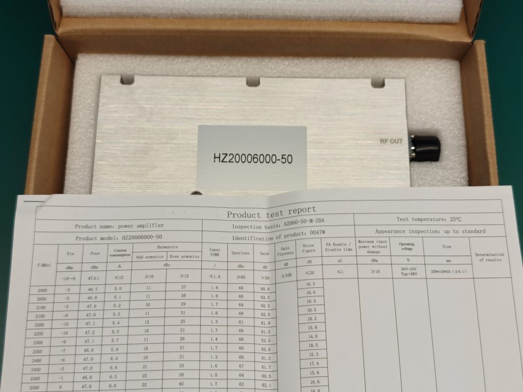
Buyers need measurements that can be traced to the tested amplifiers and their operating conditions.
For each tested S/N, a useful RF amplifier test report should connect IDC and module-terminal VDC to actual Pin and Pout at the defined test point.
Frequency, waveform, temperature, load, test-method revision, and relevant instrument information must also be identifiable.
For multi-rail modules, distinguish individual supply currents from calculated total DC input power.
The report should identify whether the measurements cover every delivered unit or a defined sample, how retests were handled, and which review rules applied.
A batch average cannot replace unit-level records where S/N traceability is required. Production-monitoring data must also remain distinct from final acceptance evidence unless the agreed procedure recognizes them for that purpose.
For shipment review, evaluate S/N-linked current records alongside the required RF performance and protection acceptance checks, rather than treating current spread as sufficient evidence.
A buyer should be able to select a reported IDC value and identify the unit, operating point, measurement method, and resulting engineering decision.
Conclusion
RF PA current spread reveals differences in DC input demand between amplifiers delivering the same specified RF output. Reliable interpretation requires matched operating conditions, defined measurement boundaries, and enough measurement capability to distinguish unit differences from test variation.
Before judging a batch, record Pout, Pin, VDC, IDC, and temperature for each tested S/N. Check repeatability and residual operating-point effects, then use approved review rules to determine which results require investigation. A high-current reading alone does not establish a defect or acceptance failure.
Engineers evaluating RF power amplifier modules can use these measurements to review RF amplifier power supply requirements, including current margin, and define the batch evidence needed for a project.
An RFQ for current-spread evaluation should specify frequency, target Pout and tolerance, waveform and duty cycle, supply-voltage range, load, cooling and thermal conditions, batch quantity, sampling method, applicable current limits or review triggers, and S/N-linked reporting requirements.
Contact RF SKYPOWER with those requirements to discuss the relevant product scope and measurement evidence. Specific batch-current performance and formal acceptance must be established from the corresponding test results.