










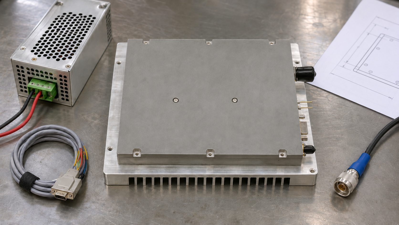
In an RF power amplifier module vs pallet comparison, the quoted configuration defines what the supplier provides and which power, cooling, control, protection and verification tasks remain with the OEM. The terms module, pallet and connectorized unit describe construction and interfaces.
Before estimating the OEM’s work, identify each quotation’s delivered assembly, external interfaces and included accessories. Check which options still need selection and who will perform the remaining integration tasks.
1.Module, Pallet, and Connectorized Unit: Where Does the Supply Boundary Sit?
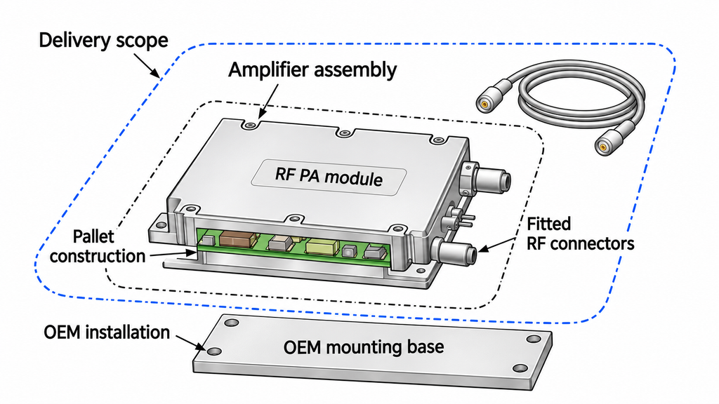
A pallet commonly describes RF power devices and associated circuitry assembled on a circuit board and metal baseplate. An RF PA module is a broad term for an amplifier assembly intended for integration. A connectorized RF power amplifier, or connectorized unit, presents fitted RF connectors at its external RF interfaces. These descriptions can overlap.
For procurement, define the RF PA module boundary around the actual delivered assembly and the interfaces the OEM must connect. A label helps identify the construction; the configuration documents establish what the supplier will provide.
Distinguish the amplifier assembly boundary from the complete delivery scope. External supplies, cables or controllers may be included in the shipment, while their installation and system integration can remain assigned to the OEM. Scope varies by model and ordering option. Use the matrix to check each configuration’s interfaces and functions. The OEM-work column covers items not supplied and implementation or verification tasks assigned to the OEM.
| Supply item | Pallet | RF PA module | Connectorized unit | OEM remaining work | Confirmation basis |
|---|---|---|---|---|---|
| RF amplification and matching | Extent of board-level matching; impedance at the RF terminations | Internal RF stages and any external network required at module ports | Port impedance and location of the stated RF reference planes | RF transitions or external matching not supplied; assigned connection work | RF block diagram; port specifications, reference planes and operating conditions |
| Physical RF interfaces | Board pads, pins or fitted connectors; required transitions | RF termination options and mating parts for the ordered module | Connector type, gender, position and supplied mating accessories | Mating parts, cables and adapters not supplied; assigned installation | Interface and outline drawings; accessory list |
| Bias network | Bias components on the board; externally accessible bias nodes | Internal bias functions; external rails or settings still required | Bias requirements at DC/control terminals, separate from RF connectors | Bias hardware not supplied; assigned bias connections and settings | Bias description; pin assignments; supply requirements |
| Power-up/shutdown sequencing | Presence and scope of an onboard sequencer | Whether sequencing is internal and which host inputs it requires | Sequencing requirements at the power and enable interfaces | Sequencing hardware not supplied; host enable and timing tasks as assigned | Operating instructions; timing and enable specifications |
| Main DC and auxiliary supplies | Rails required at pallet supply pins or pads | Module input rails and any included DC conversion | Power input connection; inclusion of any separate supply accessories | Power sources and distribution not supplied; assigned wiring and return paths | Electrical requirements; power pinout; delivery list |
| Enclosure, shielding and mounting | Board, baseplate and any supplied cover | Enclosure options, shielding provisions and mounting features | Supplied housing or bracket options; connector and cable clearances | Chassis, shielding or brackets not supplied; assigned mechanical integration | Mechanical drawings; mounting requirements; hardware list |
| Cooling and thermal interface | Baseplate contact surface and specified cooling conditions | Thermal interface and cooling hardware included in the selected option | Heatsink, fan or cold-plate options associated with the order code | Thermal materials or cooling hardware not supplied; assigned installation and checks | Thermal conditions; installation instructions; accessory schedule |
| Monitoring and alarms | Sensor and alarm signals, if provided, at board terminals | Sensing and alarm functions included in the module specification | Monitoring pins or communications functions available on the ordered unit | Readout hardware or sensing not supplied; assigned alarm handling | Signal and pin definitions; protocol where applicable; function description |
| Protection action and recovery | Any onboard response and its required external intervention | Any implemented automatic actions and their reset/recovery requirements | Specified action, reset and recovery at the unit’s control interface | Required protection functions not supplied; assigned reset and system interlocks | Protection behavior and recovery specifications |
| Control and communications | Enable/status pins and any separate supplied controller | Logic interface, optional control hardware and applicable firmware functions | Control connector, electrical interface and any supported communication protocol | Host hardware, harnesses or software not supplied; assigned system coordination | Pin/electrical definitions; protocol where used; software scope |
| External RF support/components | Driver, filter or isolator stages shown within the pallet boundary | RF support functions inside the module and any separate quoted accessories | Internal RF functions and separately supplied coaxial accessories | Required external RF components not supplied; assigned integration work | RF block diagram; interface requirements; included-item list |
| Documentation and configuration identification | Pallet identification, board revision and applicable assembly instructions | Model, ordering suffix and hardware/firmware revisions where applicable | Unit order code and identifiers for included accessories | Maintain the configuration record; obtain missing applicable interface documents | Identified drawings, manuals and agreed delivery documentation |
| Test and acceptance evidence | Pallet tested, its fixture and external test support | Module revision, test configuration and evidence coverage | Ordered unit and accessory combination covered by the evidence | System verification and additional evidence collection assigned to the OEM | Agreed test records, conditions and model/sample/batch/unit identification |
Confirm which items the quotation includes, which options remain unselected, and which items are excluded. For included hardware, identify what is built into the amplifier assembly and what is supplied as a separate accessory. If an item appears only in a photograph or test setup, request its delivery status before counting it as supplied.
2.Who Provides RF Matching, Bias, and DC Power?
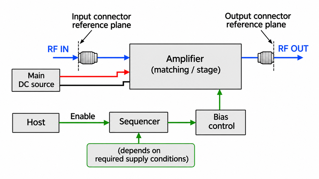
Where RF matching is included, identify its specified ports and assign the remaining connections to the rest of the system.
Locate the RF reference planes
A reference plane is the physical location at which an RF quantity or specification applies, such as a board termination or connector interface. Confirm where input and output impedance, drive level and output power are specified, together with the applicable frequency range and operating conditions.
Assign the work outside the stated RF ports: any transition from a board termination to a cable, required mating connectors or adapters, and connections to adjacent RF stages. Confirm whether each required driver, filter or isolator is included within the quoted assembly, supplied as a separate accessory with the order, or left for the OEM or another supplier to provide. Include each only where the application requires it.
If one offer specifies output at the amplifier connector and another at a fixture connection, establish how those reference planes relate before comparing their output claims. An undefined measurement reference plane leaves the corresponding performance comparison unresolved.
Separate bias functions from the power supply
Keep three responsibilities distinct: establishing the device bias, controlling the required power-up/shutdown sequence, and providing the main and auxiliary DC power.
For the selected configuration, establish which rails must enter the assembly, what external bias settings or commands remain necessary, and who provides the power source and distribution. Record responsibility for DC wiring, return paths, auxiliary supplies and enable control. In the interface agreement, specify which sequence any internal sequencer manages and which supply conditions and commands it requires.
Record the owner and applicable specification for each RF connection, supply rail and control dependency. Obtain missing port, supply-rail or sequencing requirements before committing to the affected interface.
3.Who Owns the Enclosure and the Complete Cooling Path?
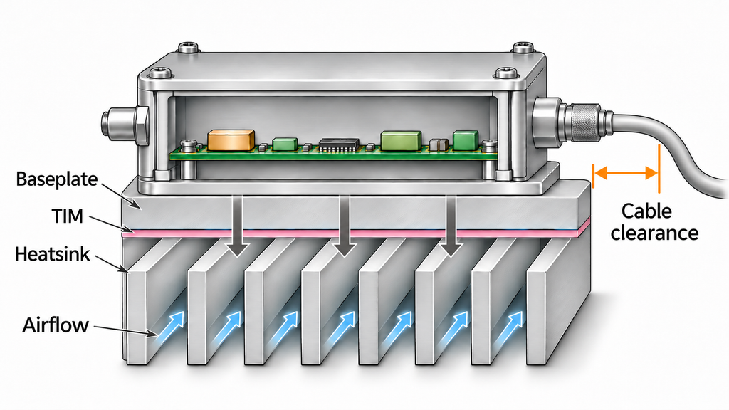
Determine where the mechanical package ends and where the installed cooling system begins. Identify the supplied circuit board, baseplate, cover or enclosure, brackets and mounting hardware. Then assign responsibility for the thermal interface material, heatsink or cold plate, and any required airflow or liquid cooling infrastructure.
For a specified baseplate temperature, record the measurement location and who will maintain that condition during operation. Keep ambient, baseplate and reported sensor temperatures identified separately. Where a quoted result relies on a laboratory cold plate, obtain the applicable thermal boundary conditions before using it to assess the OEM installation.
Mechanical integration also needs space for mating connectors, cable bends, airflow and service access. Confirm who supplies the mounting interface and who verifies the complete installation. A supplier’s test fixture or demonstration chassis belongs in the delivery only when it is explicitly included.
Use the specified temperature reference, mounting conditions, operating duty and confirmed cooling hardware to assess the installed cooling path.
4.Which Protection and Control Functions Are Included?
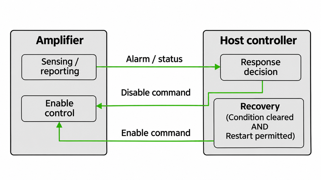
Define each required protection function through sensing, decision, action and recovery. For each stage, identify what happens inside the amplifier assembly and what depends on an external controller, power supply or host system.
Consider a quotation that lists a temperature sensor and an alarm output. Determine whether the assembly also evaluates a threshold and performs a specified action, such as reducing power or disabling amplification. If the host must act on the alarm, its input hardware, software and control connection remain part of the system scope. The listed sensor or alarm establishes only the function explicitly described; action and recovery need their own confirmation.
Establish whether the unit resumes operation automatically, requires a reset command, or depends on another defined intervention. Confirm what enable and disable commands do, the default state at power application, and the behavior relevant to the system’s interlocks. Request the applicable behavior and interface definitions for the ordered configuration.
Identify the control connector’s pin assignments, signal directions and electrical signal levels. If the interface carries digital communications, also confirm the protocol and command definitions. Establish whether the required host software, harness, controller and user interface are supplied or remain with the OEM. When firmware affects the available functions, tie the description to the applicable firmware revision.
Record who detects the condition, executes the response, permits restart and verifies the behavior after integration. Compare alarm reporting and automatic action separately. Where an action or recovery step has no implementation owner, resolve that responsibility before approving the protection scope.
5.What Evidence Defines the Delivered Configuration?
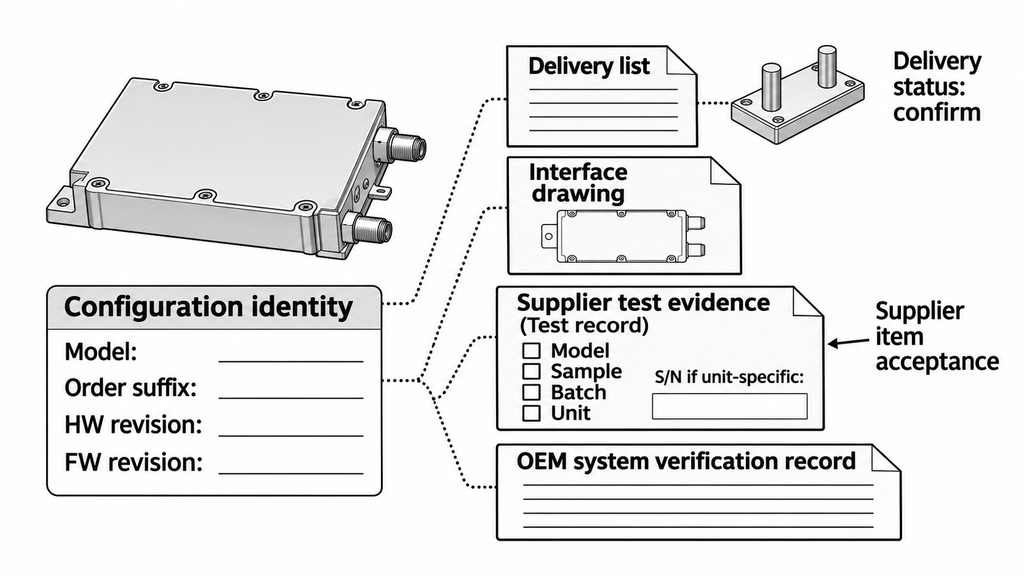
Identify the exact model, ordering suffix and applicable hardware or firmware revision before deciding whether a document supports the order. Connect that identity to the delivery list, outline and interface drawings, installation requirements and agreed test evidence. A test arrangement may include a supply, cooling fixture or external RF component that has a separate delivery status.
Identify what each result covers: the model’s characterized design, a particular sample, a batch within a stated scope, or an individual delivered unit. “Tested” alone does not specify which records will accompany the shipment. Where the project requires individual-unit results, request a link to the unit’s serial number (S/N) and the applicable configuration and test conditions.
For acceptance, request evidence tied to the delivered configuration, with the required coverage agreed before ordering. Resolve differences in external hardware or operating conditions that affect the result before relying on it for acceptance. Compare results only when their reference planes, operating conditions and evidence coverage are aligned.
Assign supplier assembly acceptance and OEM system verification separately. Supplier acceptance covers the agreed delivered item under its defined test conditions; OEM verification covers its integration into the installed system. Before ordering, agree which documents and records must accompany the shipment, how they identify the configuration, and who completes the remaining verification.
6.Which Supply Boundary Fits the OEM’s Integration Capability?
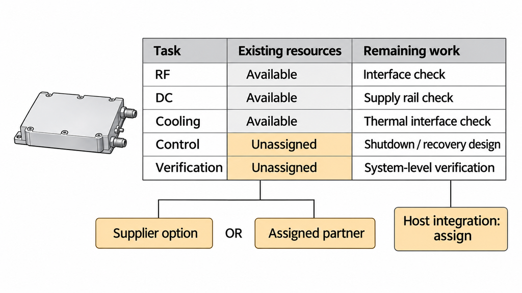
Choose a configuration whose remaining tasks the OEM can complete with available resources or explicitly assigned external support. The relevant resources include RF integration, power, mechanical and thermal design, controls, and verification.
If the OEM already has a DC supply, cooling assembly and host controller, check each against the candidate’s input rails, thermal interface and control requirements. Reuse those resources where the requirements align; otherwise, identify the additional hardware or engineering work before comparing the complete offers.
If the OEM cannot implement the required bias sequence, close that gap by selecting a configuration with the required sequencing function explicitly included, or by assigning an external implementation owner. Apply the same rule to a required shutdown response: establish who performs the action and who controls recovery. Where the OEM needs fitted RF connectors, specify those interfaces in the order and allocate DC, cooling and control work separately.
Compare offers using the assembly price plus the cost of external hardware, engineering and verification assigned to the OEM. Resolve any unsupported task through additional supplied items or a named integration partner before committing to that configuration.
To compare quotations on the same operating basis, align frequency, output definition and reference plane, available input drive, signal type and duty cycle, DC conditions, cooling, supplied accessories and evidence scope. Where only part of that basis is aligned, limit the comparison to those defined items.
When specifying RF SKYPOWER’s standard and custom RF power amplifier modules, identify the DC supply, cooling and host-control provisions already available, then define the remaining items requested from the supplier. Record the proposed configuration in the RFQ using these fields:
- Product identity: model, ordering suffix, and applicable hardware and firmware revisions.
- Quoted scope: quotation revision, included items, unselected options and exclusions.
- OEM provisions: RF, DC, mechanical, cooling and control resources already available, together with those still to be provided.
- Documents and evidence: required interface documents, applicable operating conditions, and the agreed scope of test evidence and records to accompany delivery.
- Open items: unresolved questions, the person or team responsible for closing each one, and the milestone by which confirmation is required.
Conclusion: Assign the Remaining Work Before Ordering
Before ordering, confirm the exact configuration, including the amplifier assembly, included accessories, applicable revisions, interfaces, external operating conditions and evidence coverage. Identify unselected options, items to be provided by the OEM or another supplier, and tasks still awaiting an owner. Assign each remaining task and close any critical gap that affects the procurement scope.
Operating limits, protection thresholds, application suitability and acceptance values need evidence for the specific model and project. Check the documented functions of the enclosure, RF connectors and sensors, and the scope of any “tested” claim. The agreed delivery documents establish the complete supply commitment.
For an RF SKYPOWER configuration review, provide the frequency range, output definition and reference plane, available input drive, signal type and duty cycle. State the DC, cooling, mechanical and control conditions and the requested model or configuration. List the items requested from the supplier, those the OEM or another supplier will provide, the required evidence, and any open questions with their owners. Request confirmation of the proposed configuration, delivery scope and supporting documents.