










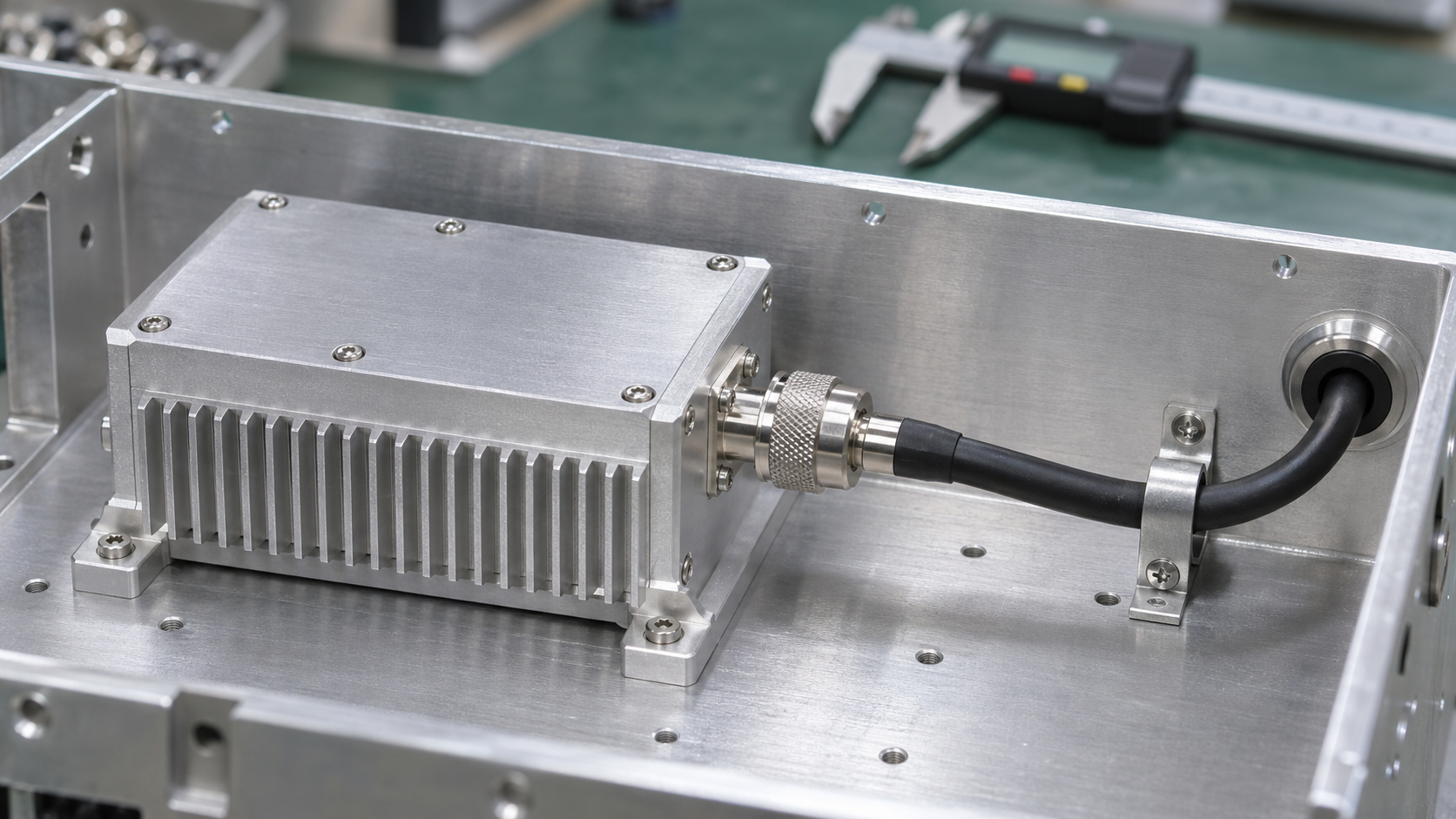
A chassis plate and cable layout are ready for release when the selected RF power amplifier module’s mechanical interface agrees with the OEM drawing and the actual mating components. The mechanical interface control document (ICD) identifies the configuration and drawing revisions that govern RF power amplifier module mounting. Catalog length, width, and height describe only part of the installation.
An outline may cover the bare module while leaving its locating features, connector protrusions, cable exit geometry, and assembly access undefined. Hardware and connector options can change those details. First establish which configuration and drawing revision the quoted dimensions represent.
1. Why Overall Dimensions Cannot Release an RF PA Chassis Design
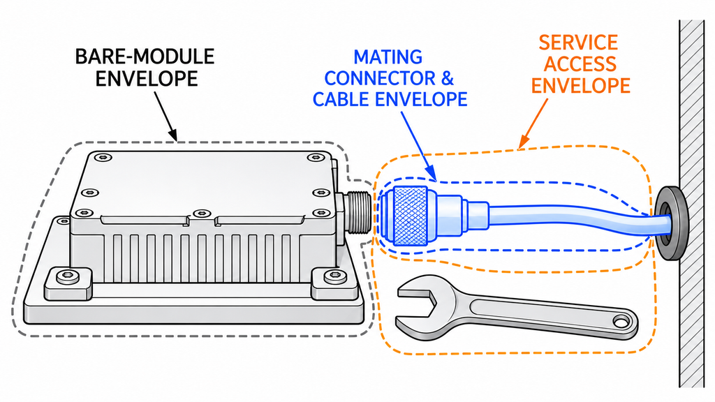
The listed dimensions of an RF amplifier module describe the boundaries identified by the source drawing. Check whether they include mounting flanges, connector noses, hardware, and other projections. Request the missing geometry before deciding whether the module will fit the plate, mate inside the chassis, and remain accessible for service.
Three different envelopes matter:
- Bare-module envelope: the controlled outline of the applicable module configuration, including any explicitly defined projections and mounting features.
- Mated operating envelope: the installed module plus the actual RF, DC, and control mating parts, their backshells or cable exits, and the space occupied by the routed cables.
- Assembly and service envelope: the additional approach, tool movement, insertion, disconnection, and withdrawal space needed to install or maintain the unit.
A connector may clear a partition when mated yet leave no room to tighten or disconnect it.
Record the module part number, hardware or connector option, mounting orientation, supplier drawing number, and revision before carrying dimensions into CAD. The supplier’s mechanical drawing controls the module as specified; the OEM plate drawing controls the host structure; the selected connector and cable documents control their mating hardware. Where one source stops short of an installed envelope, the integrator must establish the missing geometry with the responsible party before releasing the affected layout.
2. Define Mounting Datums, Hole Positions, and Tolerances
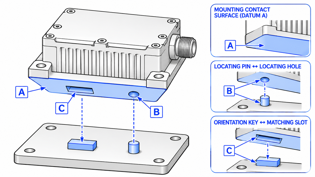
A machinable mounting pattern needs a functional datum scheme or equivalent coordinate reference alongside nominal hole spacing. It should tell the chassis designer where the module sits, which direction it faces, and how the holes relate to the surfaces or features that actually locate it.
The mechanical drawing should identify the applicable mounting contact surface, locating edges or features, coordinate directions, hole-center locations, hole diameters, and positional tolerances. Where relevant, it must also distinguish clearance holes from tapped holes, define blind-hole usable depth, and show flange geometry and the space required for fastener heads and installation tools. Thread engagement and other fastener geometry must be checked against the actual module and host arrangement, not selected from a generic PA mounting assumption.
Not every mounting hole is a locating feature. A pattern of clearance holes may provide clamp-up while a separate edge, pin, or other feature establishes position. Treating all hole centers as precision datums can impose the wrong manufacturing requirements or hide an unresolved fit. A conceptual scheme might call the contact surface A, a locating feature B, and an orientation feature C; those letters illustrate the relationship, not a datum convention guaranteed for any RF SKYPOWER model.
The OEM designer must map the supplier’s controlled feature locations into the chassis coordinate system and evaluate the resulting tolerance stack. If datum origins or critical tolerances remain unclear, hold release of the mounting-hole machining drawing until the discrepancy is resolved. Once the mounting geometry is defined, joint preload, torque, and retention can be addressed through the separate fastener reliability review.
3. Control Baseplate Contact, Flatness, and TIM Geometry
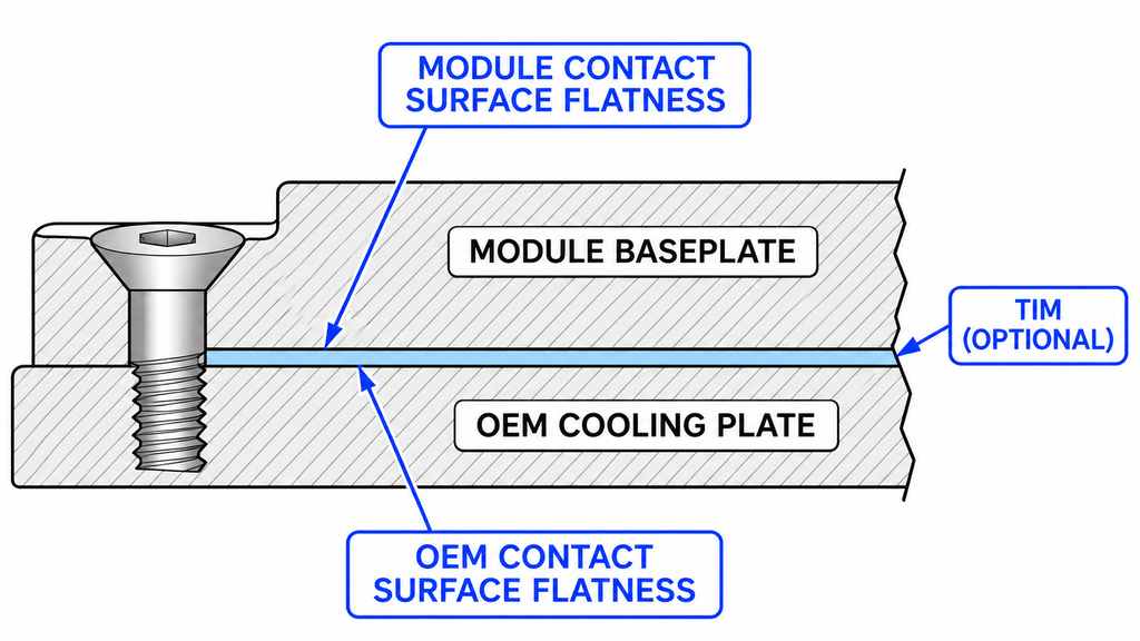
The module baseplate and the OEM mounting or cooling plate each need controlled contact-surface requirements. Flatness on one part does not establish the condition of the other, and a general chassis finish note may leave the heat-transfer contact region undefined.
For each side, establish the applicable contact footprint, datum reference, flatness evaluation area, surface condition, and any restrictions around holes, counterbores, steps, or protruding fasteners. Check whether local burrs, raised features, reliefs, or unsupported regions could prevent the intended seating. The drawing and inspection method should refer to the surface that will actually be assembled, not merely a convenient outer face.
Thermal interface material (TIM) adds its own installation requirements. The selected module and project design need to establish whether TIM is used, its type, coverage area, and any applicable installed-thickness or compression requirement. These conditions interact with plate geometry and the mounting process. Confirm the installed contact condition against the selected material and the applicable module requirements rather than relying on a generic pad or compound designation.
Review electrical bonding and insulation separately. The TIM’s thermal function alone does not specify chassis-ground conductivity or electrical isolation; confirm those properties against the selected material and the grounding design. With the contact geometry defined, the thermal integration assessment can determine whether the cooling path has enough margin under the intended operating conditions.
4. Specify Connector Orientation and Mated Keep-Out Envelopes
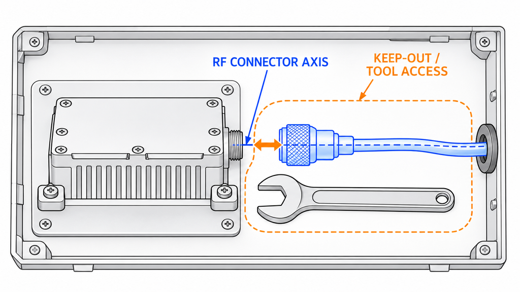
Use the connector drawing and actual mating part to define the installed connector envelope. For every port on the selected module, record its position and axis relative to the approved mechanical datums, interface type, mating gender where applicable, and matching component. This includes RF IN and RF OUT where so designated, plus DC and control connections when fitted.
Assess the connection in its final mounting orientation. The keep-out should accommodate the mating connector body, coupling mechanism, backshell or strain-relief transition, and the tool or hand approach needed to engage it. Also check the insertion and withdrawal direction. A wall or adjacent module can clear the finished connector while preventing the mating action itself.
The OEM integration drawing should identify who controls each adjacent partition, shield, clamp, and cover. The selected connector and cable-assembly documents define the mating geometry, while the project ICD assigns responsibility for resolving interface conflicts. Together these sources establish the required keep-out; its value depends on the actual configuration.
When the mated geometry is available, check interference in the configured assembly and record the components modeled. Then examine tool approach and withdrawal paths, which a static no-clash result may miss.
5. Reserve Cable Bend, Strain Relief, and Service Clearance
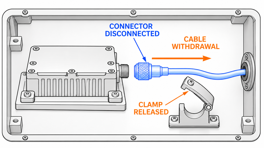
After the mating connector is defined, check what happens immediately beyond it. The first cable bend may occupy more space than the connector body. Use the minimum bend-radius and handling limits for the selected cable assembly, including its connector termination; distinguish a one-time installed bend from repeated flexing if the application involves movement. A limit published for one coaxial construction should not be transferred to a different cable.
Route the cable from the connector through its required exit or straight section, first bend, and support point. The chassis or cable-support design should carry cable weight, vibration, and installation loads through suitable strain relief rather than through the module connector. Record who controls the clip or bracket and check its clearance from the plate, cover, and adjacent electronics.
Service clearance depends on the work a technician must perform. Decide whether the project requires access to disconnect a cable, turn a coupling tool, remove a cover, or withdraw the module without dismantling unrelated equipment. The required sequence may differ from the normal operating arrangement; a service path that is temporarily occupied by a removable item needs an explicit, approved maintenance assumption.
If the cable assembly, support arrangement, or withdrawal sequence remains undecided, hold the affected cable-layout freeze until those conditions are resolved. Static clearance alone cannot establish service access.
6. Reconcile the Supplier Mechanical ICD with the Chassis Drawing
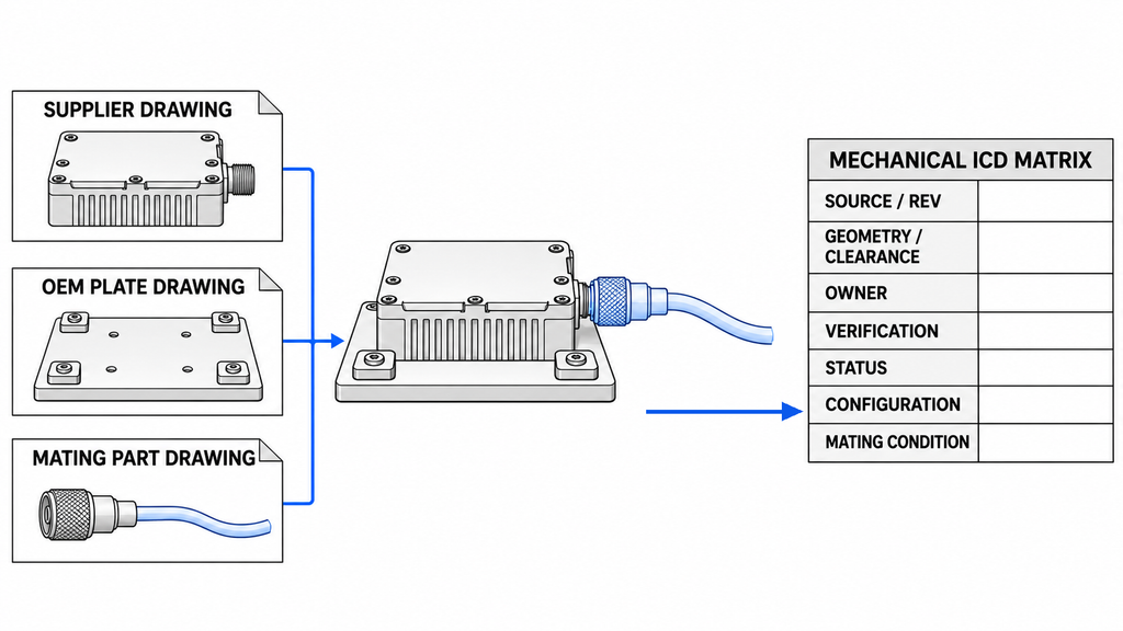
The project team uses the ICD to reconcile three interfaces: the supplier’s configuration-specific module geometry, the OEM’s chassis and contact plate, and the selected mating connectors and cable assemblies. Compare the geometry only after mapping the supplier and OEM datums and confirming the same module configuration, mating state, and applicable drawing revisions. Each controlled requirement needs a source revision, an OEM counterpart, a verification method, and an owner authorized to close discrepancies.
Populate the Mechanical ICD Interface Matrix from the drawings for the selected configuration before machining release. Create a separate entry for every fitted RF IN, RF OUT, DC, and control connector; the combined category labels below do not imply a shared mating envelope. The “Open” entries are review prompts for a project-specific ICD, not findings against a particular module. Replace them with supporting evidence, a disposition, and the responsible approver’s decision.
| Interface Item | Applicable Module / Configuration | Controlled Source & Revision | Datum / Geometry / Tolerance / Clearance | OEM Mating Condition and Owner | Verification Method | Open Item / Approval Status |
|---|---|---|---|---|---|---|
| Mounting orientation and datums | Selected model and hardware option | Supplier mechanical drawing, applicable revision | Contact datum, locating features, axes and orientation: verify on drawing | Host coordinate system; OEM mechanical owner | Datum mapping and drawing review | Open: confirm datum origin and approvals |
| Mounting holes and fastener geometry | Selected mounting variant | Supplier hole detail and OEM plate revision | Centers, diameters, positional tolerance, through/tapped features, applicable depth and tool access | Matching plate holes and fastener stack; OEM mechanical owner | Tolerance-stack and assembly-access review | Open: confirm hole data and fastener fit |
| Module and host contact surfaces | Selected baseplate and cooling interface | Module contact specification and OEM plate drawing revisions | Contact footprint, local flatness, surface conditions, steps and reliefs | Host plate/cold plate; OEM mechanical and thermal owners | Drawing comparison and specified surface inspection | Open: verify both contact surfaces |
| TIM interface | Applicable TIM configuration, if used | Approved module/project TIM specification and process revision | Material, coverage, installed geometry or compression condition where specified | Host contact process; OEM thermal/assembly owner | Specification and process compatibility review | Open: confirm TIM and installed condition; N/A with reason if absent |
| RF IN / RF OUT mating envelopes | Each actual fitted RF port, recorded separately | Module port drawing plus mating connector drawings/revisions | Port location and axis, mated protrusion, coupling and tool keep-outs | RF cable assembly and adjacent structures; assigned OEM integration owner | Mated assembly interference and access check | Open: verify each port and mating part |
| DC / control mating envelopes | Each fitted DC/control port, recorded separately | Applicable connector and module interface drawing revisions | Mating direction, body, latch/backshell and withdrawal clearance | Cable assembly, cover and partitions; assigned integration owner | Configured assembly and service-access review | Open: verify fitted connector; N/A with reason if absent |
| Cable first bend and strain relief | Selected cable assemblies | Cable/connector specification revisions and cable routing drawing | Installed bend limit, exit path, first bend and supported length | Clips, brackets and routing; assigned cable-design owner | Route check against component limits | Open: confirm bend and support conditions |
| Tool and service envelope | Selected chassis and maintenance arrangement | Module access requirements and OEM assembly/service revision | Fastener-tool sweep, connector access and module extraction path | Adjacent assemblies and removable panels; assigned service owner | Assembly sequence and withdrawal-path review | Open: verify tool and withdrawal path |
| Revision applicability and change impact | Ordered module option and current OEM build | Supplier drawing, OEM plate, cable routing and change records | Confirm all geometry is for the same configuration and mating state | Supplier/OEM interface approvers | Cross-document revision and discrepancy review | Open until revision baseline and approvals are recorded |
If the mounting holes do not align, the supplier first confirms the applicable datum scheme and module option; the OEM then checks the tolerance stack before revising the plate. If a contact step or counterbore obstructs seating, the mechanical and thermal owners reconcile contact geometry and TIM requirements. For a backshell collision, check the actual mated assembly before changing adjacent structure or selecting a compatible mating part. If the first bend exceeds the available space, the cable-design owner revises the route and strain-relief position against the selected cable specification. If the module cannot be withdrawn, the service owner verifies a workable removal path or an approved disassembly sequence. Record each disposition and its supporting revision in the matrix.
Close each difference against a revised controlled source or an approved project disposition, not against an informal dimension copied from an email or another module variant. A fit check of one sample can inform the review, but it does not replace the specified tolerance analysis or establish conformity across production units.
7. Apply a Mechanical ICD Release Gate Before Machining
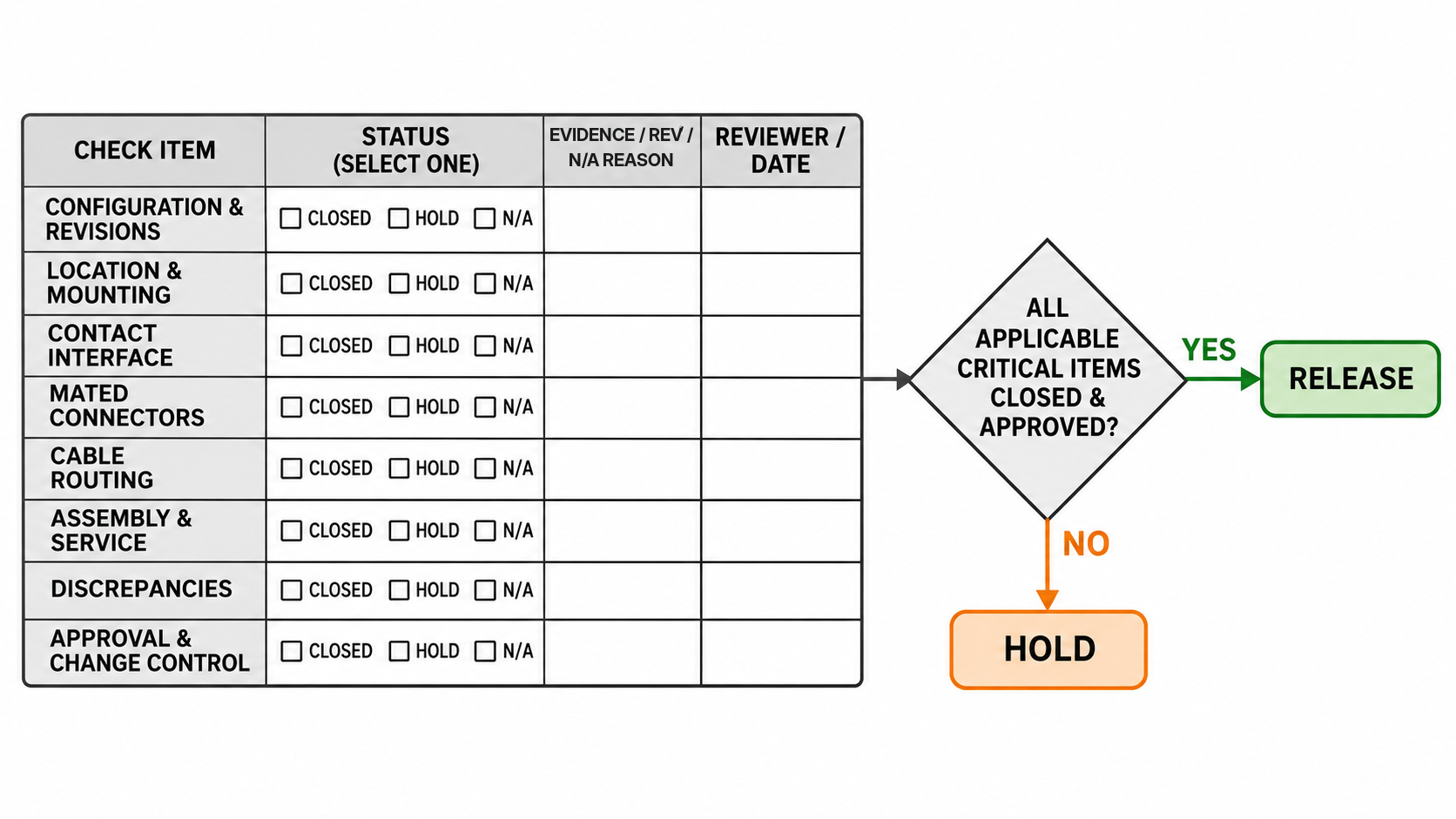
Use the Pre-Machining Release Checklist to decide whether the chassis plate and cable layout can proceed. For each item, record Reviewed / Closed, Hold — Clarification Required, or N/A — With Reason, together with the supporting document and revision, reviewer, and closure date. A checked box confirms that the review was performed; the recorded status determines whether the item is closed, on hold, or justified as not applicable. An unchecked item or missing status remains unresolved.
- Configuration and revisions: The module part number, hardware and connector options, supplier drawing, OEM plate drawing, and cable-assembly revisions refer to the same build. Status: ____; Evidence/Rev: ____; Reviewer/Date: ____.
- Location and mounting: Datums, hole locations, tolerances, fastener interfaces, and tool clearance have been checked together. Status: ____; Evidence/Rev: ____; Reviewer/Date: ____.
- Contact interface: Both mating surfaces, relevant flatness and surface conditions, TIM arrangement, and any bonding or isolation requirement are controlled. Status: ____; Evidence/Rev: ____; Reviewer/Date: ____.
- Mated connectors: Each fitted RF, DC, and control port has its own mating part, keep-out, coupling access, and removal direction assessed. Status: ____; Evidence/Rev: ____; Reviewer/Date: ____.
- Cable routing: Component-specific bend limits, first-bend space, strain relief, and support ownership are defined. Status: ____; Evidence/Rev: ____; Reviewer/Date: ____.
- Assembly and service: Required installation, tool, cover, and module-withdrawal operations have a workable path. Status: ____; Evidence/Rev: ____; Reviewer/Date: ____.
- Discrepancies: Critical matrix differences are closed by controlled revision or documented approved disposition; N/A decisions include a reason. Status: ____; Evidence/Rev: ____; Reviewer/Date: ____.
- Approval and change control: Supplier and OEM interface responsibilities, sign-off records, and re-review triggers are identified. Status: ____; Evidence/Rev: ____; Reviewer/Date: ____.
Final release record: Decision RELEASE / HOLD: ____; approved module, plate, and cable drawing revisions: ____; supplier/OEM signatories: ____; date: ____; change conditions requiring renewed review: ____.
Release the affected mechanical drawings for machining when every applicable critical item has been closed and the responsible authorities have approved the current configuration. Missing hole-position tolerances, undefined mating connectors, contact-interface conflicts, or blocked service paths place the relevant drawing release on HOLD; they do not classify the module as defective.
A module hardware revision, connector option change, modified mounting plate, replacement mating cable, or altered adjacent structure can invalidate a previously closed interface. Review the change against the matrix and reopen affected checklist items before the revised drawing is released. This release gate concerns mechanical design readiness; first-article dimensional checks, assembled thermal performance, vibration durability, EMC, and RF acceptance remain separate project activities.
Conclusion: Freeze the Mechanical Interface Before Releasing the Chassis
An RF PA chassis plate and cable layout have a defensible mechanical release basis when the selected module configuration, supplier and OEM datums and hole tolerances, intended contact and TIM geometry, actual mated connector and cable envelopes, service paths, and controlled drawing approvals agree. Similar outer dimensions, the same number of mounting holes, or a photograph that appears to show a fit do not establish those conditions.
The ICD matrix and pre-machining gate can identify a ready-to-release mechanical interface or the exact information holding it back. They cannot supply universal model-specific flatness limits, TIM compression values, connector clearances, cable bend radii, or final acceptance results. Those require the applicable supplier, component, OEM, and project records; mechanical drawing release does not certify physical assemblies, thermal or vibration performance, or RF results.
Before contacting a supplier, complete the matrix using current document revisions, resolve discrepancies with the responsible OEM and component owners, and record the checklist decision and change triggers. If the PA configuration still needs to be identified, RF SKYPOWER’s standard and custom RF power amplifier module range provides a starting point for the project discussion; the selected configuration still needs its controlled mechanical definition.
For an interface review or RFQ, provide the candidate model and hardware revision, applicable supplier drawing, OEM plate or chassis envelope, mounting orientation, contact and TIM conditions, and selected mating connector and cable assemblies. Include cable routes, the required service direction, unresolved hole, tolerance, or keep-out differences, and whether the next step is drawing reconciliation or a scoped prototype fit check.