










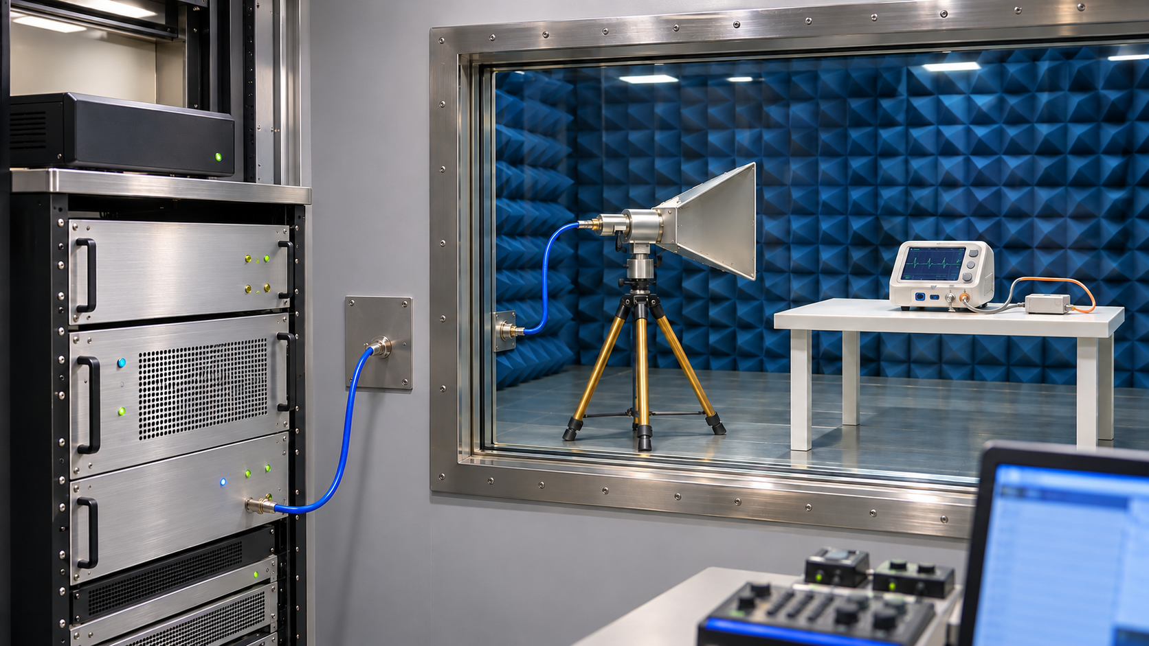
For medical device EMC testing, choose the radio-frequency (RF) amplifier and antennas from a defined immunity test plan. The waveform, field level, exposure geometry, and device monitoring needs determine whether the chain can meet that plan.
Electromagnetic compatibility (EMC) also covers emissions and other immunity tests. The equipment choices here concern RF immunity for medical electrical equipment and systems covered by IEC 60601-1-2. An amplifier’s wattage and an antenna’s frequency range do not tell a laboratory whether it can run the required test. Start with the device and its intended environment.
1. Confirm the Applicable Standard and Intended-Use Environment
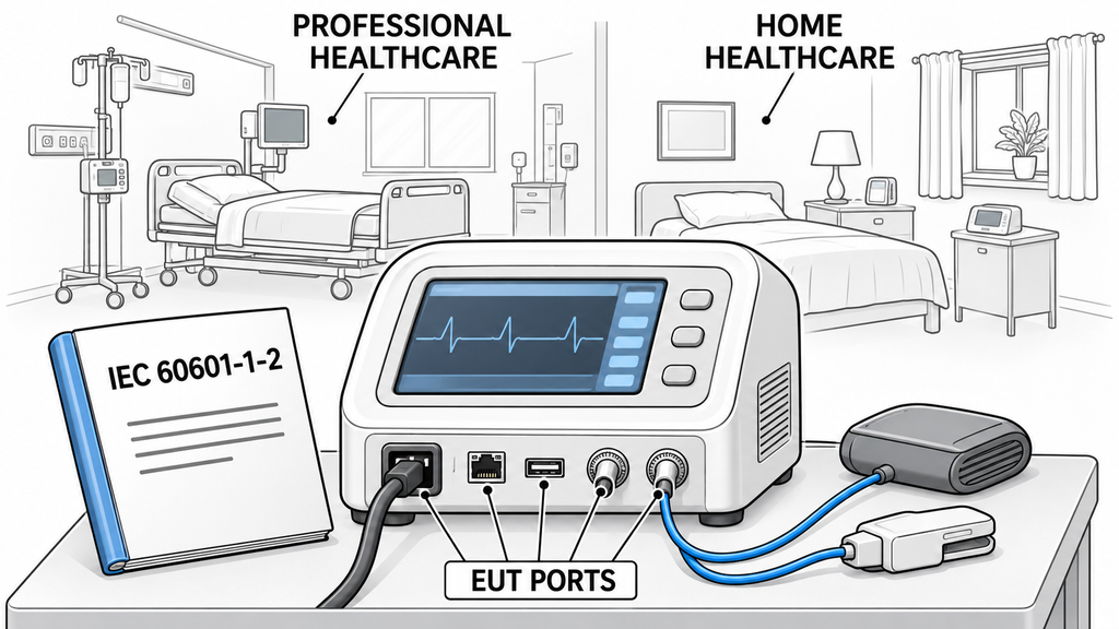
Confirm the applicable product standard before specifying equipment. IEC 60601-1-2 addresses electromagnetic disturbances in relation to basic safety and essential performance. Its 2014 edition with Amendment 1:2020 forms consolidated Edition 4.1. Record the edition and amendments required for the project, together with any applicable particular product standard.
A medical purpose does not automatically bring a device within IEC 60601-1-2. Check the applicable standards separately for in vitro diagnostic devices, laboratory equipment, and active implants. A particular product standard may add to or change the requirements.
The place of use matters. A device intended for a professional healthcare facility may face different test requirements from one used in a home or special environment. Record the target market and intended locations.
For US submissions, check the FDA’s recognition of Edition 4.1. The FDA does not recognize Figure 3’s classification of nursing homes as a home healthcare environment. Nor does it recognize the Table 8 Note k exemption from IEC 61000-4-6 testing for signal input/output cables shorter than 1 m. Account for both exceptions when defining the environment and ports.
Check the device ports and cable conditions. RF applied to the enclosure can call for different equipment from RF coupled into a cable. Make that distinction before selecting the amplifier and antenna.
Use the IEC 61000-4-series method editions specified in the test plan. A newer method edition does not automatically replace the version required for the medical project.
The equipment brief should name the standards, revisions, environment, ports, and RF tests. Any uncertainty about applicability must be settled with the device manufacturer and laboratory before setting frequency or output requirements.
2. Define the Device Configuration and Performance Monitoring
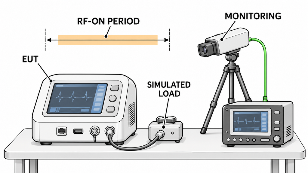
Before choosing equipment, decide how the medical device will operate during RF exposure and what the laboratory must observe. The manufacturer should set the relevant functions, limits, and pass/fail criteria before testing.
Essential performance covers clinical functions whose loss or degradation beyond defined limits would create unacceptable risk. Turn those limits into checks the laboratory can make on the equipment under test (EUT). A device may neither restart nor raise an alarm while its output moves outside the permitted range.
A device may have no identified essential performance. That finding still needs a risk-based justification, and the test plan still needs device-specific pass/fail criteria for basic safety and intended operation.
Specify operating modes, power-supply states, accessories, loads, simulated inputs, and cable layout. For patient connections, include the required loading or simulation. All of these details must match the test plan.
For continuous RF disturbances, assess the specified performance during and after exposure. A recovery allowance used for a transient test cannot simply be carried over to RF immunity testing.
The test controller must hold each exposure long enough for the required observation and the device’s response. The amplifier and cooling system must sustain that RF-on time. A short output measurement cannot prove they will.
Tie device logs, measurements, and any observed deviations to the applied test conditions. The monitoring system needs enough time resolution to catch relevant changes without significantly disturbing the EUT or the test.
The test plan should show which functions to watch, how long to watch them, and who set each criterion. If a critical function cannot yet be observed, leave the related control, timing, and RF-on-time requirements open.
3. Match Each RF Immunity Requirement to Its Test Chain
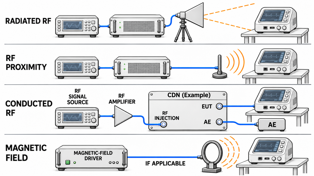
Before sharing hardware between tests, establish where and how each disturbance is applied. Overlapping frequency bands may still need different couplers, antennas, and level-setting methods.
| RF immunity task | Applicable basis and conditions | Where the disturbance is applied | Equipment-chain requirements | What cannot be carried over |
|---|---|---|---|---|
| General radiated RF immunity | Applicable medical product requirements and the referenced IEC 61000-4-3 method | The specified test area covering the EUT and relevant cabling | RF source, suitable amplifier and transmitting antenna, power measurement, field probe for field setting, and test control | A general radiated setup does not establish coverage of every proximity or conducted test |
| Proximity fields from RF wireless communications equipment | Applicable IEC 60601-1-2 proximity requirements, with the prescribed frequencies, waveforms, and geometry | Specified positions near the EUT | Waveform-capable RF source, suitable antenna and positioning, amplification where required, and method-specific field setting | A general sweep or its calibration does not establish the required proximity exposures |
| Conducted RF immunity | Applicable port conditions and the referenced IEC 61000-4-6 method | Cables and ports through the specified coupling arrangement | RF source and amplifier, coupling/decoupling networks or other permitted injection devices, and level-setting equipment | A radiated field level does not establish the required conducted injection level |
| Proximity magnetic fields, where applicable | Applicable product or amendment requirements and the referenced method, including IEC 61000-4-39 where invoked | Specified locations exposed by the prescribed magnetic-field source | Suitable drive equipment, coil or loop, and method-specific level setting and verification | An amplifier-and-horn configuration does not establish the prescribed magnetic-field exposure |
IEC 60601-1-2:2014+A1:2020, Clause 8.11, covers proximity magnetic fields from 9 kHz to 13.56 MHz. First check the equipment and attached accessories for magnetically sensitive components or circuits. If none are present, no further evaluation under that clause is needed. If they are present, the enclosure or accessory’s physical design may keep those parts at least 0.15 m from the field sources specified in Table 11 during intended use. Without that design-based separation, a documented risk analysis may support omitting Table 11 tests. If the risk is unacceptable, carry out the tests using IEC 61000-4-39. The manufacturer may also test directly. Record the applicable decision in the test report or risk management file.
One test may need a coupler; another may need an antenna or magnetic-field source. The same signal source or controller can serve several tests, but each setup needs its own supporting evidence.
Do not treat all wireless communications proximity tests in IEC 60601-1-2 as IEC 61000-4-39 tests. A short test distance alone does not establish electromagnetic near-field operation.
When the test method or coupling point is unclear, do not assume the existing chain can be reused. Shared frequency coverage is not enough to justify that decision.
4. Specify Usable Amplifier Output for the Required Waveforms
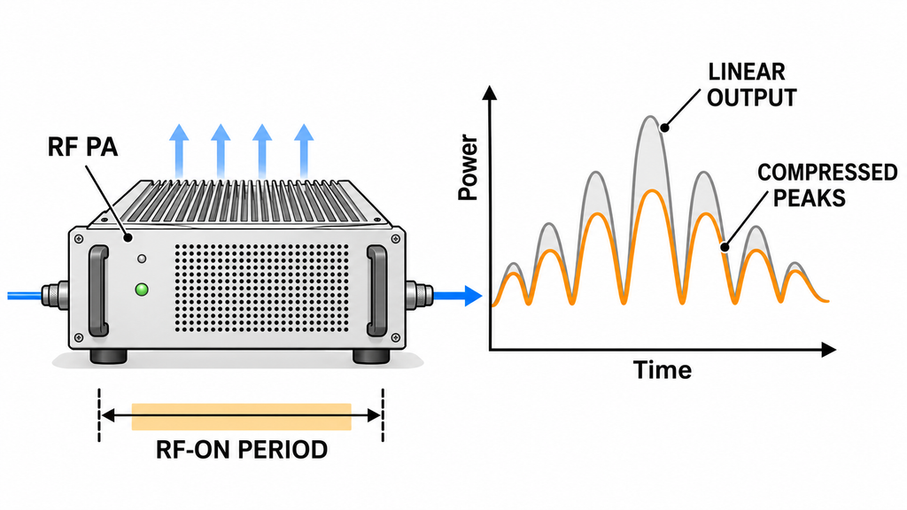
Specify usable power at each required frequency, for the actual waveform and RF-on duration. A single wattage figure does not answer that question.
Check whether the stated power refers to an unmodulated carrier, modulated average power, or peak envelope power. Peak envelope power is the RF-cycle average at the crest of the modulation envelope. An amplifier may compress on waveform peaks even when its average output appears sufficient.
Ask for output and compression data at the test frequencies, with the waveform, reference plane, load, actual RF drive, and thermal conditions stated. Include cooling and run time. Power delivered to the amplifier input depends on path losses and any upstream active gain. The generator’s display setting is not a measurement at the amplifier connector.
At the 1 dB compression point (P1dB), gain has fallen 1 dB below its small-signal value. This is different from the linearity check required by a particular immunity method. Ask what measurement supports usable output and whether thermal or mismatch protection can reduce it.
Calculate the EMC amplifier power budget using the required test waveform, antenna data, and installed-path losses. The required frequency range can narrow the shortlist of wideband RF power amplifier modules. Compare candidates only when their usable-output data cover matching waveforms and operating conditions.
Do not settle on a power class without waveform-specific and hot-state output data.
5. Choose Antennas for Each Test Band and Exposure Geometry
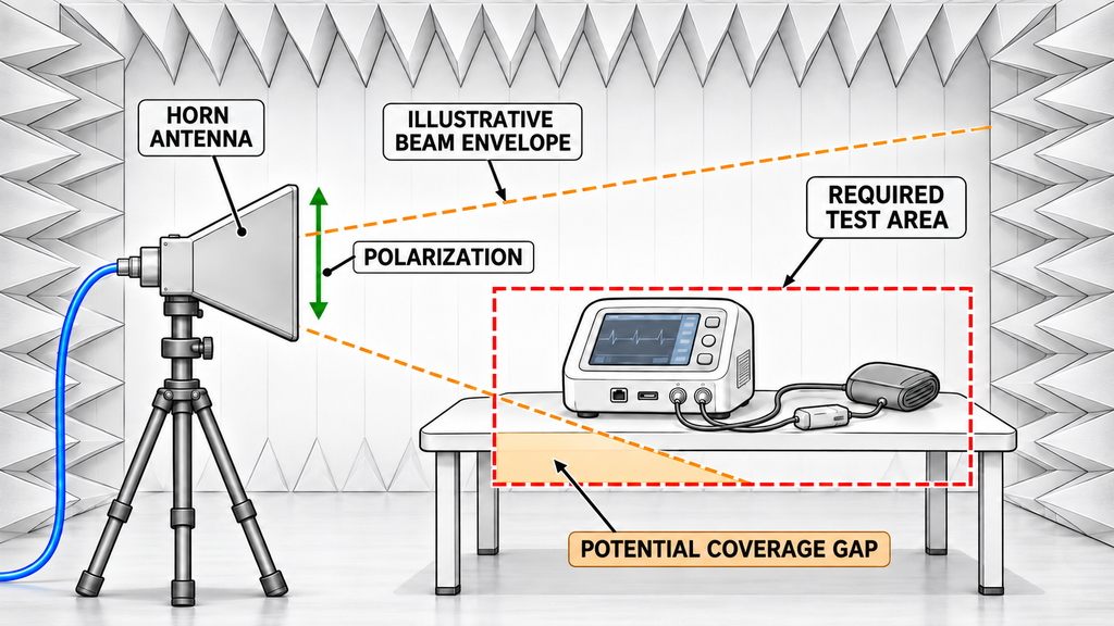
Choose antennas for the required bands and exposure layouts. Include the EUT, its accessories, and relevant patient or interconnecting cables in the layout. Their positions affect the area the test must cover.
Check frequency coverage, polarization, input-power limits, connectors, and impedance match. High peak gain may still leave part of the required area outside the beam at the test distance.
For horn candidates, use frequency-dependent gain and radiation-pattern data to check the test band. Compare gain at the same frequency and polarization, with the antenna orientation and test geometry accounted for. Check input-power ratings under the proposed conditions. Field uniformity needs calibration evidence for the radiated setup, not just antenna data.
Coils and injection devices serve different test methods. A transmitting antenna cannot replace them without method-specific justification.
For each band and exposure layout, list the candidate antenna and any missing evidence. A frequency beyond its rated range is a coverage gap. Missing setup records mean suitability remains unconfirmed.
6. Verify the Installed Chain and Its Available Margin
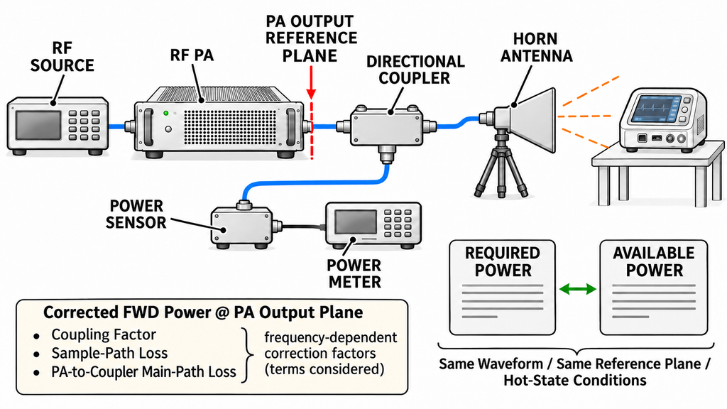
Use the power budget and component data to shortlist a chain. To approve it, check the installed source, amplifier, coupler, switches, cables, antenna, and meters against the test records. Components may meet their individual ratings while the full chain falls short.
For each radiated setup, keep the field-setting and linearity evidence required by its method. The records must identify frequency, polarization, geometry, and hardware. Field setting establishes the exposure; EUT monitoring shows how the device performs during it.
Put required and available power on the same basis
Field-setting records give the required forward power at the stated reference plane for each test frequency and setup. That plane may be the amplifier output connector or another defined point in the RF path. If available amplifier power is specified elsewhere, correct for measured main-path losses before comparing the values.
A directional coupler samples the main RF path. The sample reaches a power sensor and meter. Apply the coupling factor and sample-path loss at each frequency to recover power at the coupler’s stated plane. For power at another plane, also correct for the relevant main-path losses. Keep the remaining feed loss to the antenna separate so it is not counted twice.
Keep the raw sensor readings, correction factors, and results together. Another engineer should be able to trace each reported power value to its reference plane.
Check the limiting conditions
Compare required and available power using the same waveform, power definition, and reference plane. Check the specified duration and hot-state conditions. The weakest frequency or setup sets the practical limit.
Count each allowance once. If the required-power figure already includes feed losses, do not add them again. Waveform peaks, path losses, engineering reserve, and measurement uncertainty have different roles. Report uncertainty with the measurements; it cannot replace missing field-setting or output data.
Verify that output holds throughout the exposure while the EUT is monitored. Check test-control timing, thermal drift, and any protection-driven reduction in power. The required observation time must fit the chain’s verified operating period.
A change in antenna, RF path, monitoring equipment, or cable layout may affect earlier results. Review its impact before reusing those records. Do not approve a setup until the required waveform, thermal, measurement, and field-setting evidence is available.
7. Match Supplier Evidence to the Medical EMC Test Plan
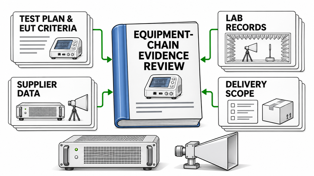
Build the supplier brief from the test plan. For each requirement, show what it changes in the equipment chain, what evidence is needed, and who must provide or confirm it.
| Defined requirement | Effect on the equipment chain | Evidence to obtain | Provider or confirming party | Action if information is missing |
|---|---|---|---|---|
| Applicable standards and intended environment | Establishes the required RF tests, bands, waveforms, and levels | Test plan identifying applicability, standards, revisions, and environment | Device manufacturer and test laboratory | Resolve applicability before fixing the equipment scope |
| EUT configuration and performance monitoring | Determines exposure layout, observation time, control, and operating duration | Configuration record, performance criteria, and monitoring plan | Device team defines criteria; laboratory confirms the test arrangement | Clarify the affected function or observation method |
| Frequencies, waveforms, and required output | Determines usable amplifier output, drive, and thermal requirements | Output and compression data with power definition, drive, load, cooling, and duration stated | Amplifier supplier; laboratory or integrator checks the match | Request aligned data before selecting a power class |
| Exposure geometry and coverage | Determines antenna configurations, polarization, and positioning | Antenna data and field-setting records for the intended configuration | Antenna supplier and test laboratory | Verify coverage before approving the combination |
| Measurement reference planes and RF paths | Determines how readings relate to required and available power | Reference-plane definitions, calibration records, and path corrections | Laboratory or system integrator | Align definitions and corrections before comparing results |
| Module, component set, or complete-system supply | Determines who provides the source, amplifier, antenna, cooling, control, measurement, and integration | Itemized quotation, interface details, and responsibility allocation | Supplier, integrator, and buyer | Align the delivery boundary before comparing quotations |
An amplifier datasheet supports only the performance it documents; it cannot show that a medical device passed EMC testing. Likewise, the laboratory’s field calibration does not set the device manufacturer’s performance criteria.
Every report should identify the tested item, revision, setup, and operating conditions. Include a model or serial number where needed to show what the result covers.
Compare quotations only when the technical conditions and scope of supply match. Ask for missing curves or setup records before choosing a supplier or configuration.
Conclusion
Choose a chain that can deliver the specified waveform and exposure while the laboratory monitors the device’s performance. The applicable standards, use environment, and EUT configuration set those requirements. Rated wattage and frequency coverage alone cannot prove the chain is ready for testing.
The test plan narrows the component shortlist. Final suitability still depends on project-specific limits, installed-chain verification, and the medical device’s test results. Each answers a different question.
Before requesting quotations, gather the test conditions and existing records. Assign missing evidence to the device manufacturer, equipment supplier, integrator, or laboratory. This makes quotations easier to compare and shows which decisions remain open.
RF SKYPOWER can review candidate RF power amplifier modules against those conditions and identify missing supplier data. Share the standard and revision, target market, use environment, RF tests, frequencies, waveforms, levels, and exposure geometry. Include device dimensions, relevant cables, monitoring needs, and any field-setting or forward-power records. State the available RF drive, power supply, cooling, control interfaces, and required delivery scope. Mark unknowns instead of filling them with assumptions.