










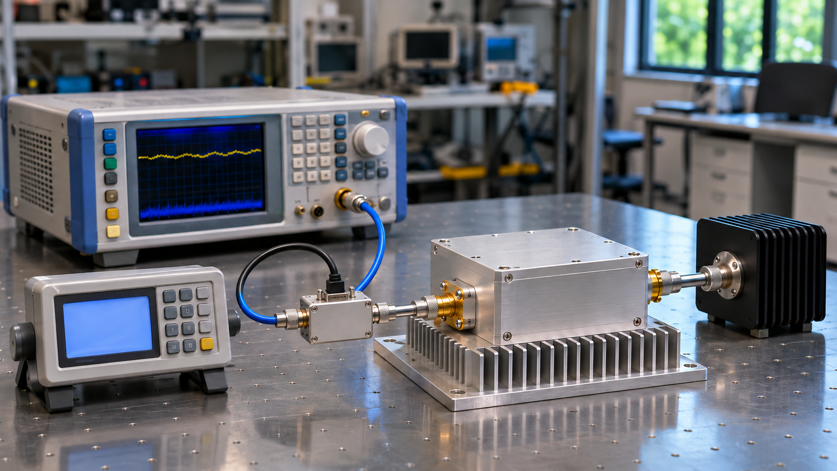
An RF signal generator must deliver the required signal at the power amplifier’s input, with enough level accuracy and spectral quality for the measurement. Frequency range and maximum output power are only the starting points. Modulation bandwidth, noise, and switching behavior become important when the test calls for them.
A generator may have enough output power to drive a PA yet still compromise the result. An uncertain input level can distort a gain measurement, while unwanted source signals can appear at the amplifier output. Start with the PA test conditions, then assess the generator specifications against them.
1. Define the PA Drive Requirements Before Comparing Generator Specifications
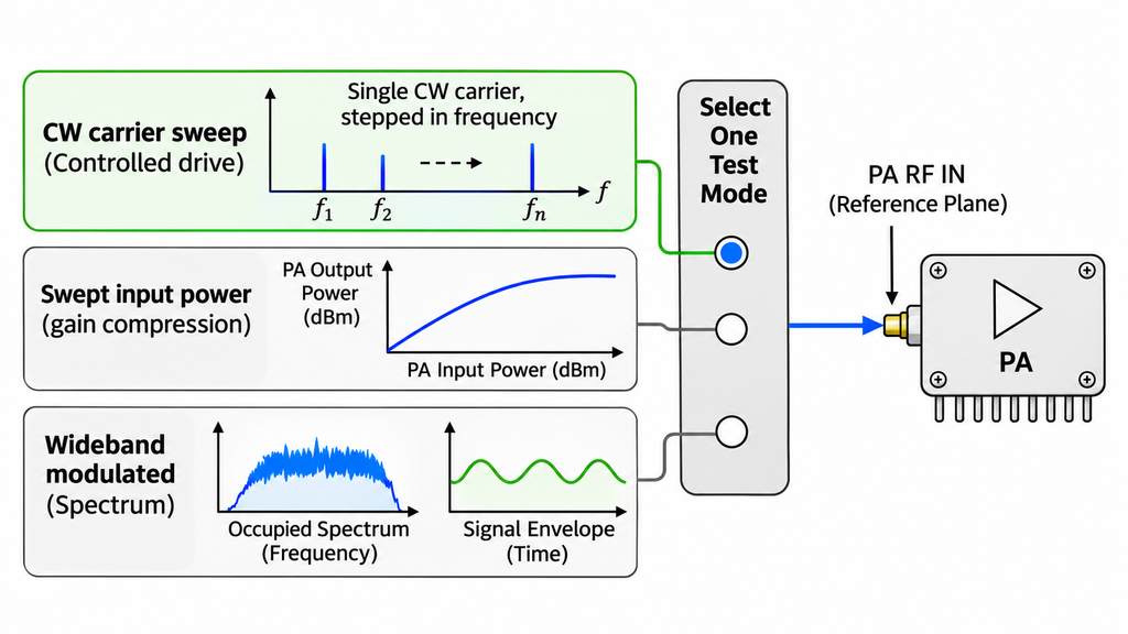
A CW gain sweep, a compression test, and a wideband modulation test need different source capabilities. Define the task before comparing instruments.
Record the test frequencies, waveform, and required power range at the PA input reference plane, normally the RF input connector. Identify the PA operating point as well. The drive needed for a target output can change with frequency, temperature, and compression.
Keep the intended operating range separate from the PA’s absolute maximum input rating. The absolute maximum is a limit, not a target. At the other end of the range, a high-gain PA may require so little input drive that the generator’s minimum usable output matters.
Two RF power amplifier modules with the same rated output power may require different input levels. Use the selected model’s specifications and input-to-output performance data. Small-signal gain alone will not tell you the drive needed near compression.
If the PA input range is missing from the available documentation, resolve it before choosing the source. Rated PA output power cannot establish that range on its own.
2. Check Output Level Accuracy, Repeatability, and Available Drive Power
Generator output levels are usually specified in dBm. Compare the minimum and maximum usable levels at your test frequencies, in the required signal mode, and with the installed options. An output rating near the center of a range may not hold at its edges.
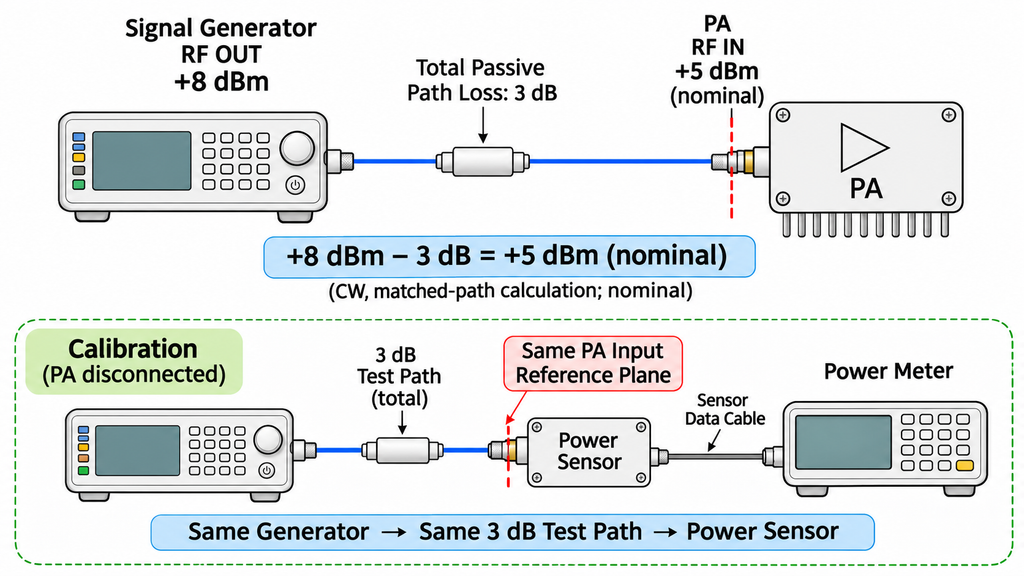
Account for the path between the generator and PA. Cables, switches, attenuators, and fixtures reduce the available drive. An additional driver stage changes the source chain and can introduce its own errors.
For a CW test, suppose the PA needs +5 dBm at its input and the passive path loses 3 dB. The generator must then deliver approximately +8 dBm at its output. This is a nominal matched-path calculation with no external driver. It does not include mismatch, measurement uncertainty, or extra headroom. Verify the actual PA input level and stay within the amplifier’s documented limits.
Separate accuracy, repeatability, and resolution
Level accuracy tells you how close the output is to the set value, often as a tolerance in ±dB. Repeatability tells you how consistently the generator returns to a level. Resolution is the smallest adjustment it allows. A source can repeat the same error every time; fine setting steps do not make that error disappear.
Read the conditions attached to the accuracy figure. Its validity may depend on frequency, output level, temperature, warm-up, calibration status, or leveling mode. A typical value and a guaranteed specification are different kinds of evidence. Neither describes the uncertainty of the complete test path by itself.
Check the power at the PA input
The generator’s calibration normally refers to its own output port. Downstream components introduce loss, mismatch, and sometimes gain before the signal reaches the PA.
RF PA input-power measurement therefore needs a defined reference plane, suitable path corrections, and a measurement method appropriate to the signal. Loss correction alone does not remove mismatch or measurement uncertainty.
In gain and compression testing, input uncertainty matters most when it could change the reported result or pass/fail decision. Measure the drive under those conditions rather than compensating by raising the generator setting.
3. Evaluate Frequency Coverage, Flatness, and Frequency Stability
A generator’s tuning range tells you where it can place the carrier. It does not guarantee the same output level or quality at every frequency. Check the intended test points, particularly those near the PA band edges.
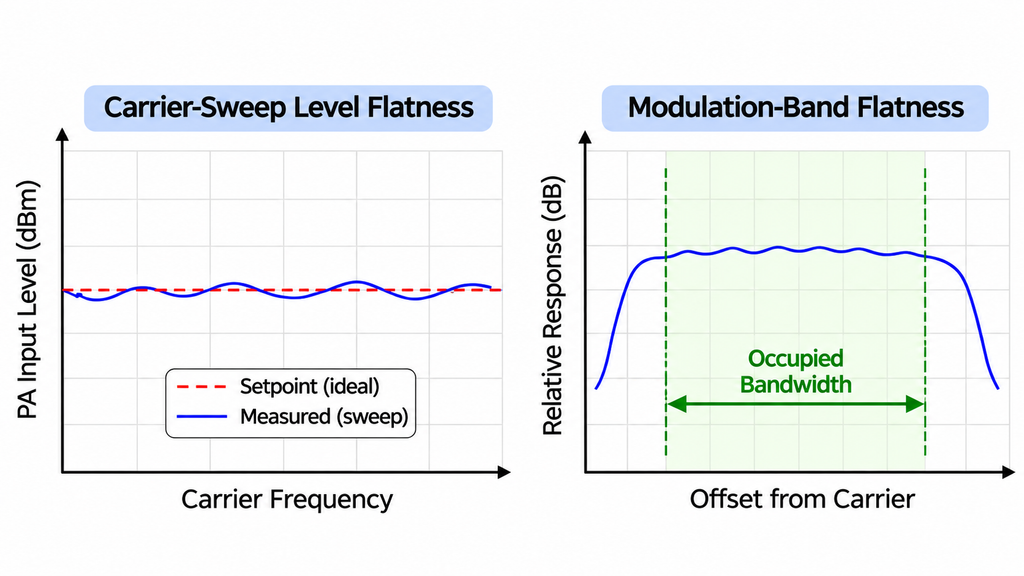
During a frequency sweep, a fixed generator setting may produce different power at the PA input. The generator’s level response and the path’s frequency-dependent loss both contribute. Without accounting for them, a change in drive can look like a change in PA gain.
Two flatness specifications deserve separate attention. Carrier-sweep level flatness describes level variation as the generator tunes between frequencies, typically in dB. Modulation-band flatness describes the response across the occupied spectrum of a signal centered on one carrier. Good results for one do not establish the other.
Frequency resolution is the tuning step size, often given in Hz. Frequency accuracy is the error relative to the requested frequency; an oscillator specification may express part of that error in ppm. Stability describes how frequency changes with time and operating conditions.
For a test close to a narrow filter edge, frequency accuracy may matter far more than it does for a broad gain survey. Use the oscillator’s accuracy, aging, warm-up, and external-reference specifications to judge that requirement. A small tuning step is not evidence of a small frequency error.
4. Match Modulation Bandwidth and Waveform Capability to the PA Test
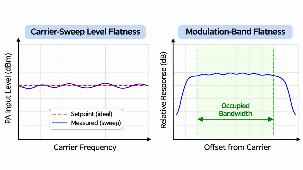
RF tuning range, modulation bandwidth, and PA instantaneous bandwidth describe different limits. The generator must tune to the carrier and produce the required occupied bandwidth there. The PA must support that signal bandwidth under the intended operating conditions.
For a multichannel generator, review the bandwidth available on each RF channel. A combined figure does not necessarily describe what one channel can produce.
Verify the waveform, not just its name
A listed modulation format is a starting point. Check the I/Q arrangement, sample rate, filtering, and waveform memory or playback limits for the version you intend to use.
Waveform quality also matters. Error vector magnitude (EVM) expresses modulation error and may be reported as a percentage or in dB. Amplitude and phase response across the occupied bandwidth can affect the signal even when the nominal bandwidth is sufficient.
Before judging PA EVM or adjacent-channel leakage, characterize the corresponding impairment in the signal at the PA input reference plane. Use the intended waveform and power conditions. The output analyzer’s noise floor, distortion, and dynamic range must also be adequate so its limitations do not dominate the reported result.
Keep average power and waveform peaks distinct
Peak-to-average power ratio (PAPR), usually expressed in dB, describes the relationship between a waveform’s peak and average power under a defined convention. A signal with high PAPR may need more instantaneous headroom than the generator’s CW output rating suggests.
Review the generator’s average and peak output limits, waveform scaling, and clipping behavior. Source clipping creates distortion before the PA has any chance to reproduce the intended waveform.
Automatic level control (ALC) can regulate output power, but its behavior depends on the waveform and operating mode. For pulses or complex modulation, use the manufacturer’s specified leveling conditions rather than assuming one ALC setting works for every test.
Equal average input powers do not make CW and modulated RF amplifier tests equivalent. Waveform peaks may drive the PA into different operating regions. Keep the waveform, power definition, and source-quality conditions together when comparing results.
5. Assess Harmonics, Spurious Signals, Phase Noise, and Broadband Noise
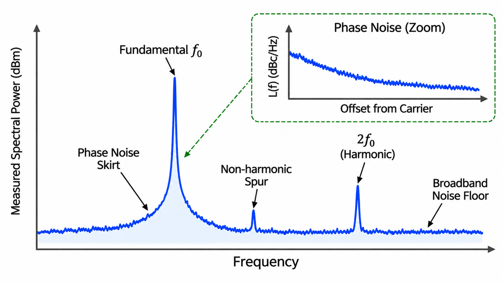
Source spectral purity matters when unwanted content at the input could be mistaken for distortion or noise generated by the PA. The relevant specification depends on what the output test is trying to measure.
Harmonics occur at integer multiples of the carrier. A harmonic already present in the drive signal may contribute to the component measured at the PA output.
Non-harmonic spurs are discrete unwanted signals at other frequencies. Their levels can change with carrier frequency, output level, and generator configuration. Harmonics and spurs may be quoted in dBc relative to the carrier or in absolute dBm; keep that distinction when comparing them.
Phase noise describes noise around a carrier caused by phase fluctuations. Values are commonly specified in dBc/Hz at a stated offset frequency. Compare generators at the same carrier and offset, not by selecting their most favorable figures from different conditions.
Broadband noise may be expressed as a power density, such as dBm/Hz, or as power integrated across a specified measurement bandwidth. Those values cannot be compared without accounting for bandwidth and measurement conditions.
A harmonic test puts a premium on source harmonic performance. A modulation-quality measurement may be more sensitive to phase noise or other in-band source errors. The source specification should follow the test, rather than a generic claim of spectral purity.
A spurious-output test becomes harder to interpret when an unwanted component is already present at the PA input. Establish a source-path baseline at that reference plane using the intended frequencies, levels, and waveforms. Make sure the measurement setup can resolve the components of interest.
A source spur does not rule out additional distortion in the PA. If the baseline is too high to distinguish the PA contribution, improve source characterization or change the test configuration before assigning a cause.
6. Verify Switching Time, Trigger Behavior, Control, and RF Interface Conditions
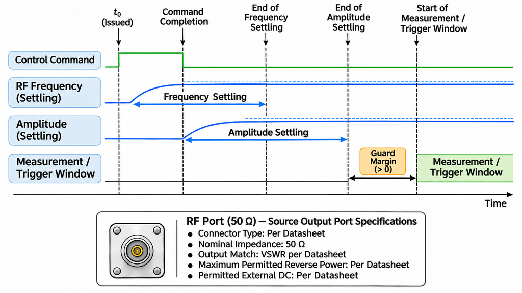
A switching-time figure in µs or ms needs a definition. Frequency settling, level settling, and waveform-start timing measure different events, each with its own tolerance. Compare the specification that matches your test sequence.
A control command may finish before the RF output settles. Where timing matters, use the generator’s documented completion or settling indication and establish the relevant trigger latency and variation. The PA’s enable time cannot stand in for the timing of the complete source-and-amplifier chain.
Remote-control support should cover the actual sequence: frequency and level changes, status readback, triggering, and RF output control as required. A network connector alone says little about timing repeatability.
At the RF port, confirm nominal impedance, output match, connector type, and the limits for reverse power and applied DC. A nominal 50 Ω interface does not guarantee a perfect match or protection against power returning from the PA chain.
If the instrument documentation does not establish the necessary timing or port limits, hold integration approval until those conditions are resolved. The implementation test plan should cover sequencing and protection behavior in the complete system.
7. Compare RF Signal Generators With a PA-Drive Specification Matrix
Use the test task to decide which specifications matter first. The matrix identifies the evidence needed for a practical comparison; it is not a model ranking or a set of universal acceptance limits.
| PA test task | Generator specifications to prioritize | Evidence to confirm |
|---|---|---|
| CW gain or compression testing | Usable output range, level accuracy, repeatability, and adjustment capability | Applicable level specifications and verified drive at the PA input reference plane |
| Swept-frequency PA testing | Carrier-frequency coverage, level flatness, and available output across the required range | Specifications or characterization at the intended frequencies, including relevant band edges |
| Wideband modulation testing | Usable modulation bandwidth, waveform fidelity, and average/peak output behavior | Evidence for the actual waveform, carrier, output level, and channel configuration |
| Harmonic or spur testing | Harmonic and non-harmonic spur levels, phase noise, and broadband noise relevant to the measurement | Source baseline and measurement conditions sufficient to distinguish the PA contribution |
| Automated switching tests | Frequency and amplitude settling, trigger behavior, and remote-control functions | Timing definitions, completion behavior, and records for the intended control sequence |
| PA interface compatibility | Nominal output impedance and match, reverse-power tolerance, and permitted external DC | Documented port ratings, calibration conditions, and compatibility evidence for the complete input path |
First decide whether the evidence is comparable. Frequency, waveform, output level, reference plane, and other material conditions need to align. If records cover only some tests, comparison is limited to those tests. Where essential conditions are missing, the affected comparison remains unresolved.
Then decide whether the generator suits the task. A documented specification may show that it meets a requirement or clearly falls short. Conditional suitability makes sense only when a supported option, configuration, or defined verification step could close a gap without contradicting a known limit. Level corrections cannot increase the generator’s maximum available output. An external driver changes the source chain and needs a separate assessment. Lack of evidence alone does not prove a product has failed.
An SDR signal source module used in an embedded PA system needs the same drive-related checks. Define its output level, waveform, and control requirements at the PA interface. If the SDR is used for calibrated measurements, establish its applicable output calibration and uncertainty as well.
Conclusion
Choose a generator whose specified performance covers the PA’s drive range, test frequencies, waveform, and measurement requirements. Confirm the signal at the PA input reference plane before relying on the results. A source may be comparable on paper yet still fail a known requirement, while missing evidence leaves the decision open.
The next step is to match each planned test against its source specifications, identify any gaps that could change the result, and verify the conditions that matter at the PA input.
RFQ: Share Your PA Drive and Signal Source Requirements
For an RF SKYPOWER PA or embedded SDR source project, send your requirements for an engineering review.
Provide the frequency range, key test points, and PA model or target output. Include the required input-power window, the PA’s documented maximum input rating, and the intended CW, pulse, or modulated waveform. Specify occupied bandwidth, the average/peak power convention, and relevant signal-quality requirements.
Also describe the RF path and its reference plane, control and trigger needs, and any calibration or verification evidence the project requires. These details allow an assessment of the proposed PA/source configuration without assuming unverified model-specific performance.