











Before buying an RF drone detection system, test the proposed setup at the site it will protect. Agree on the targets, required outputs, and success rules before flying. Then compare repeated trials with independent ground truth. Any coverage claim must stay within the signals, locations, altitudes, equipment settings, and conditions tested.
A quoted detection range says little about a particular site. Terrain, buildings, RF background activity, aircraft transmissions, and antenna placement can all change the result. Start with the signal the system needs to detect and the output the operator must receive.
1. What Does RF Drone Detection Coverage Actually Prove?
An alert confirms that the system reported an event. To use it as coverage evidence, the buyer needs to know where the signal came from and what the alert means.
An RF detector may receive transmissions from the aircraft or its controller. Aircraft-side transmissions include Remote ID broadcasts. Receiving a controller signal does not show that the receiver could hear the aircraft at its location. Under US FAA rules, Standard Remote ID broadcasts position data for the aircraft and control station. An add-on broadcast module instead reports the aircraft’s position and takeoff location. In both cases, the receiver reads broadcast coordinates; it does not measure those positions itself. Other protocols may differ. If the log does not identify the source, mark it unknown.
Test each promised function separately. Detection means a target-related alert; identification adds a supported identity or class. Location needs a position output and evidence of its accuracy, while continuous tracking needs linked updates over time. An alert-only detector need not supply coordinates, but its alert cannot stand in for location or tracking. Autonomous aircraft may still transmit RF signals. Radio-silent or unsupported targets cannot be assumed detectable.
Keep RF-only and combined-sensor results separate. An alert produced by RF, radar, and cameras together does not prove RF detection unless the RF event can be traced. If the buyer needs location or continuous tracking rather than an alert, the selected drone detection technology must first support that output.
Put the target, signal source, required output, protected space, observation window, and system mode in the test brief. If the source or output is unclear, hold that part of the coverage claim until the evidence resolves it.
2. How Should You Survey the Site and RF-Noise Baseline?
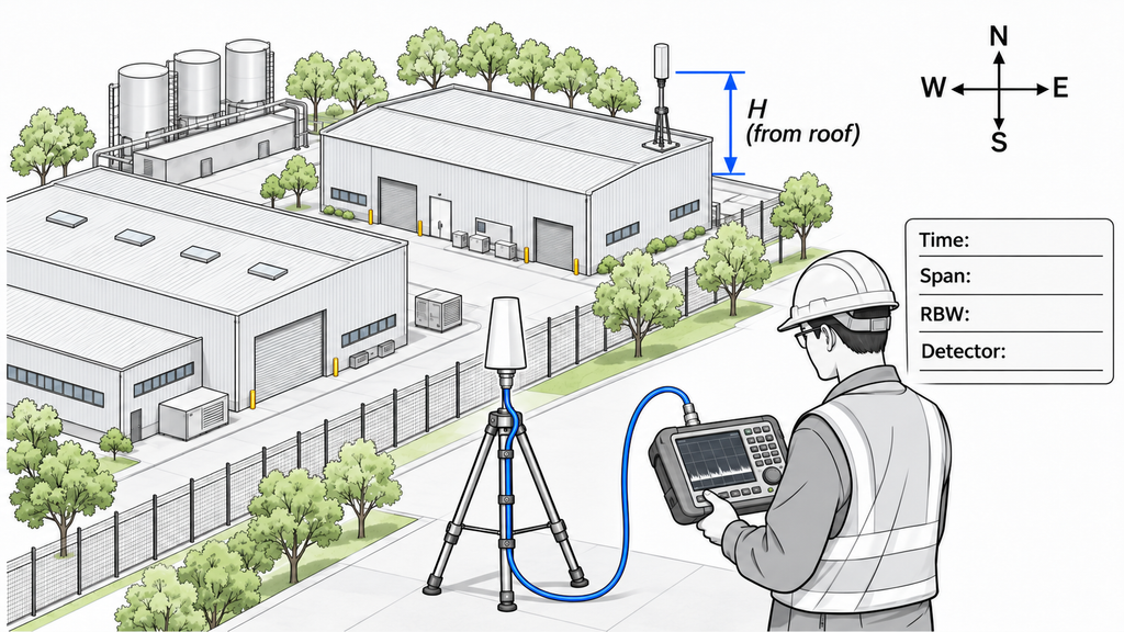
Start the site survey with a plan of the protected area and its required altitude layers. Plot sensor positions and important approach directions, then mark terrain, buildings, metal structures, and likely obstructions. For each antenna, record its orientation and mounting height. State whether the height is above local ground, a roof, or sea level so another team can reproduce the setup.
Note obstacles that may change between the trial and daily operation, including vehicles, construction, and seasonal vegetation. Keep a record of power, networking, software settings, and the route an alert takes to the operator display. These details can affect the timing of an alert. For multi-node systems, record each receiver’s position and whether events come from one receiver or combined processing. Photograph the trial setup, especially where it differs from the planned installation.
An RF-noise baseline describes the radio environment during measured periods. For each observation, note the location, time, antenna orientation, frequency span, measurement bandwidth, instrument detector mode, and other settings. Include background transmissions and periods when intermittent emitters may be active. A quiet interval cannot describe the whole day, and readings made with different settings need separate labels. The baseline documents test conditions; it does not establish detector performance or a universal noise limit.
For a fixed installation, keep the sensor position and antenna orientation in the trial record. A patrol team testing the HZ-HD03 handheld drone detector would also log where the operator stood, which direction they faced, and which mode they used on each pass. Moving the receiver changes the RF geometry, so those details matter when comparing results.
The survey should leave the buyer with a site plan, installation details, obstruction notes, and time-stamped RF measurements. Missing height references or background conditions can make a change in test results impossible to explain.
3. Which Targets, Altitudes, and Azimuths Must the Trial Cover?
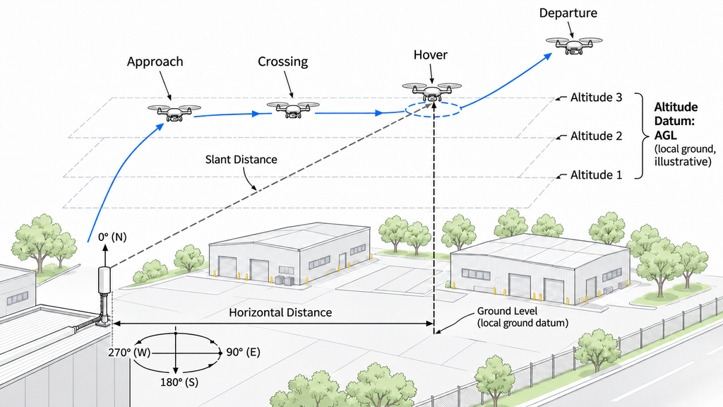
A data sheet may list a frequency band and supported protocols. Neither alone proves a target will be detected at this site. Set the trial around the protected space and required targets, and keep the supplier’s claims separate from field results.
Define the essential combinations before flying:
| Condition group | What to record | What this verifies | What cannot be concluded if missing |
|---|---|---|---|
| Target and signal | Model, firmware, controller position, protocol/band, transmissions, Remote ID state, and flight-control mode | Is the required signal state represented? | Support for untested targets, protocols, or radio states |
| Declared support and trial status | For each target and output, record supplier-declared support; whether the trial was planned and attempted; and the evidence outcome (valid hit/miss counts, indeterminate, or not yet available) | Does the field evidence test the supplier’s declared capability for that target and output? | A declaration or scheduled trial does not establish site performance without valid results |
| Spatial geometry | Altitude datum, azimuth from sensor, horizontal distance or slant range, entry and exit points | Which directions, distances, and heights were tested? | Coverage of omitted spatial conditions |
| Flight behavior | Actual approach, departure, crossing, or hover track; speed, heading, and attitude | Does the flight represent the required movement? | Performance on unflown routes or orientations |
| Sensor configuration | Installation and antenna orientation, device/software version, RF-only or fused mode, network/display path | Which configuration generated the result? | Results for another installation or operating mode |
| Environment and repetition | Obstructions, RF background, time period, observation window, and repeat opportunities | Were critical conditions repeated in a relevant setting? | Performance across missing periods or from one pass |
The site determines which altitudes, directions, routes, and repeat passes matter. An approach, a crossing, a departure, and a hover test different geometry. Choose them within approved flight limits; no fixed range or number of passes can replace the local requirements.
Mark unsupported targets as capability gaps and supported but untested targets as evidence gaps. If energy detection and protocol identification are distinct functions, assign separate success rules to each. Do not omit either category from the completed condition matrix or claim coverage where the relevant opportunity never occurred.
4. How Do You Run Repeatable Flights and Capture Ground Truth?
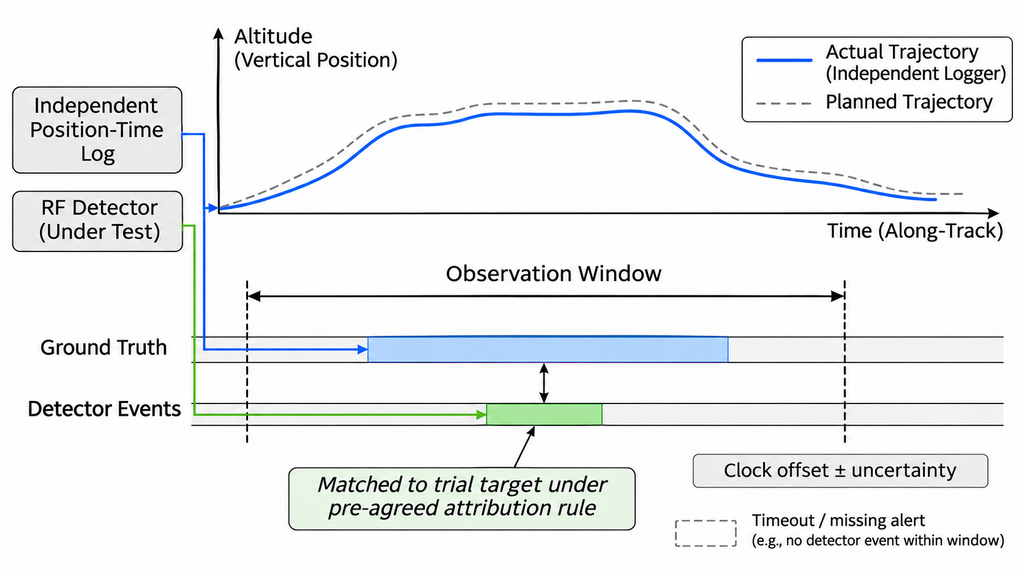
A trial needs ground truth: an independent record of where the aircraft flew and when. The detector’s own output cannot provide the reference used to judge it. Onboard logs or a separate tracker may work if their time and position uncertainty are documented and suitable for the claim. Disclose shared GNSS sources when checking location accuracy. Planned waypoints are not the actual flight path, and a decoded Remote ID coordinate cannot independently verify that same position.
Before the first flight, define a valid test opportunity. It may be a route pass or a fixed window with the required target state and independent evidence. Agree on the matching window, qualifying output, timeout, and what counts as a new alert after signal loss. A matching event must belong to the trial target, not merely occur at the right time. When other aircraft are present, timing alone may not be enough. Alert-only devices can use controlled timing association; location accuracy is a separate claim.
Align clocks across ground truth, aircraft logs, sensor events, and the operator display. Keep their offsets and uncertainty. Flag targets already active at entry instead of reporting negative latency. Count independent passes under the preset opportunity rule; repeated messages from one alert are not separate trials.
For every planned pass, retain a trial ID, target/signal state, device configuration, actual track, and clock reference. Link these to the observation window, matched event, outcome (hit, miss, timeout, or interruption), validity decision, reason, and raw logs.
Judge each trial against the output and deadline agreed before testing. A qualifying alert within that window is a hit; an absent or late alert is unsuccessful. Keep valid misses, timeouts, and detector outages in the trial record rather than discarding them. Continuous tracking requires its own continuity rule. Exclude a trial only when a pre-agreed validity condition fails for a documented reason unrelated to the detector’s output. Record the reason and repeat the trial when appropriate.
If ground truth is missing, clocks cannot be reconciled, or the alert cannot be linked to the target, mark the attempt indeterminate. Keep the reason alongside every attempt and exclusion in the trial log. The log provides the counts needed for the coverage map.
5. How Do You Turn Test Results Into an Evidence-Based Coverage Map?
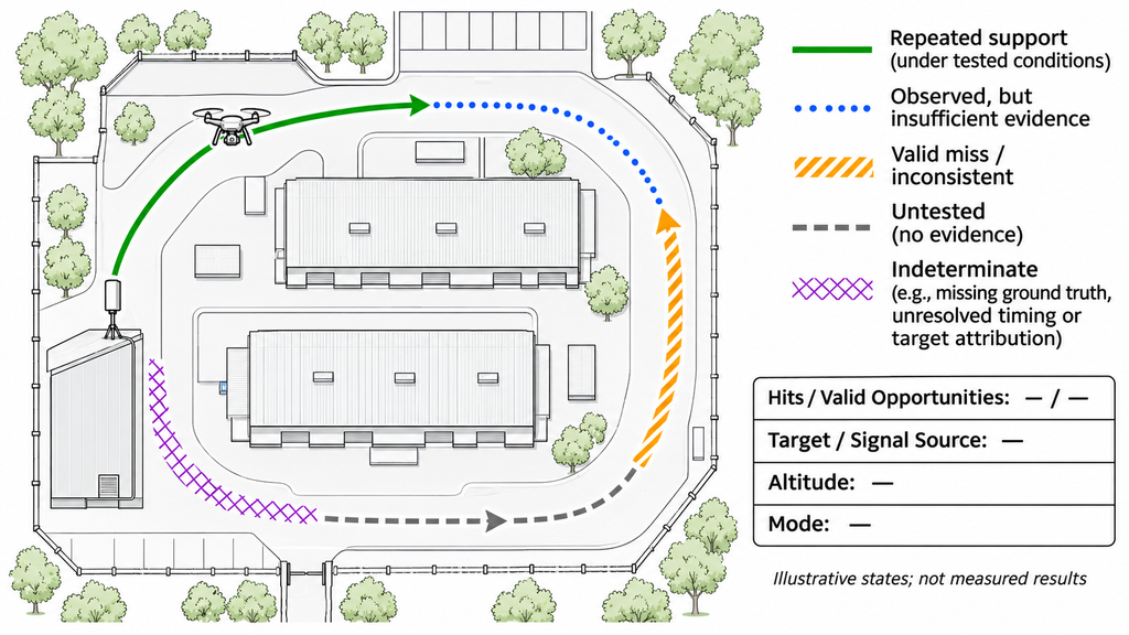
A coverage map should index actual test opportunities rather than an advertised maximum-range circle. Divide the protected space into cells or track segments at a scale supported by the flight records. Link each result to its target, signal source, required output, altitude, direction, sensor position, configuration, software version, RF background, opportunity counts, and raw logs.
A controller-side alert can be linked to an aircraft’s position only when independent ground truth and the event-matching rule establish that association. It shows where the aircraft was when the controller signal was received; it does not prove aircraft-side RF reception there. Label controller-side and aircraft-side results separately. Map each result only to the signal source and output that the test actually supports.
Before testing, agree on how many valid repeats and which conditions a map segment needs to show repeated support. Set the rule against the project’s requirements and uncertainty, then keep it fixed. The following five states are proposed for the site trial; they are not an official grading standard:
| Map state | Evidence needed | Allowed and prohibited conclusion | Next action |
|---|---|---|---|
| Repeated support under tested conditions | Valid repeats meet the pre-agreed evidence rule; logs and conditions are traceable | Supports detection under tested conditions only, without guaranteeing other heights, times, or targets | Preserve counts and limitations; check required strata |
| Detection observed; insufficient evidence | A matched alert exists, but repetition or condition coverage is insufficient | Shows an event occurred, not stable coverage | Repeat tracks and address missing conditions |
| Valid misses or inconsistent results | Independent truth confirms missed opportunities or mixed outcomes | Shows variability or a limitation; one miss is not a permanent blind spot | Inspect logs and conditions; repeat targeted trials |
| Untested | No relevant trial was attempted for the specified location, altitude, target, mode, and output | No verified coverage claim; leave the area unverified | Plan the missing opportunity |
| Indeterminate | Trials were attempted, but missing or unreliable ground truth, timing, attribution, or records prevent judgment of the specified output | The affected output cannot be judged. A valid fused-system result remains reportable when only its RF contribution is uncertain | Repair the evidence gap or report only the output supported by the records |
Filter the map by target/protocol, altitude, RF-only versus fused output, installation, and relevant time or noise conditions. A two-dimensional map does not verify the full volume above it. Predictions and interpolation may guide new flights, but they belong in a separate estimated layer.
When valid hits and misses coexist in one map segment, retain both counts. Use “Valid misses or inconsistent results” by default. Use “Repeated support under tested conditions” only if the pre-agreed project acceptance rule permits the observed miss pattern. Still display the hit and miss counts and the conditions. The map label must not conceal misses or imply performance beyond that rule.
When valid results and indeterminate attempts coexist, assign the map state using valid opportunities only if they meet the pre-agreed evidence and condition-coverage rules. Report indeterminate attempts separately; never count them as hits or misses. Do not mark a required condition as supported while its evidence remains unresolved.
The finished map should tell the buyer where evidence supports the required coverage and where another flight or better record is needed. Two colored areas are not comparable if they represent different targets, heights, or evidence rules.
6. Which Performance Metrics Make Vendor Results Comparable?
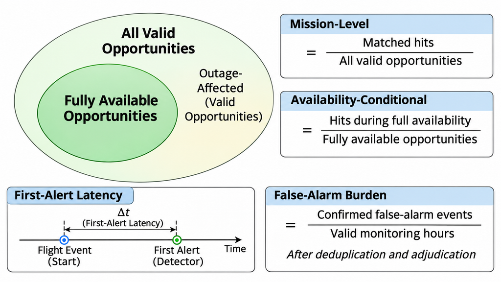
A larger detection percentage is meaningful only when vendors measured the same output under comparable conditions. Agree on the metrics before testing, then keep the raw counts, timestamps, and unresolved events. The rules below are for a site trial; they are not universal pass thresholds.
| Metric | Proposed calculation or observation rule | Report alongside it | Conditions to align before comparison |
|---|---|---|---|
| Detection rate | Mission-level rate: matched detections in the agreed window ÷ all valid opportunities, including valid opportunities affected by detector outages | Hits, valid misses, total opportunities, window, detector outages, and exclusions with reasons | Target/signal, output, route/altitude, mode, and validity rule |
| First-detection latency | Time from defined entry or start event to first matched output at a named endpoint | Timestamps, clock uncertainty, detected-case distribution, and already-active cases | Start event, sensor-log or display endpoint, synchronization, and match rule |
| Timeouts and no-detection windows | No matched event by the deadline counts as an unsuccessful valid opportunity | Timeout counts, device outages, no-event records, and undefined latency cases | Window length, timeout, operational availability, and denominator |
| False-alarm burden | Confirmed false-alarm events ÷ valid monitoring hours, using stated deduplication and adjudication | Event counts, monitoring hours, unresolved alerts, RF conditions, and downtime | Event definition, confirmation method, monitoring period, and system mode |
| Repeatability | Variation across independent repeats under the same defined conditions | Per-run hits/misses, count, spread, and relevant changes | Target, geometry, configuration, environment, and opportunity unit |
Keep two rates separate. The mission-level rate includes every valid target opportunity, even if a device outage prevents the required alert. A qualifying alert within the agreed window still counts as a hit if the device fails later. The availability-conditional rate uses only opportunities when the detector stayed available for the full test window. Report partial outages and availability separately. Because the denominators differ, do not rank these rates as equivalents.
For false-alarm burden, use only monitoring hours when the device operated and the logs were sufficient to assess its alerts. Report downtime and alerts that remain unresolved. An unmatched alert may involve another target or incomplete records; it is not automatically false. Zero confirmed false alarms describes only the period monitored. Events per hour also differ from the share of all alerts confirmed false.
An average based only on successful detections can hide missed deadlines. Report timeouts and opportunities without a valid latency value alongside the average. If you report a statistical interval, explain how you calculated it, what counts as a sample, and whether samples are independent. Multiple messages from one encounter do not create independent trials.
Compare results only for matching targets, signals, outputs, modes, routes, environments, and counting rules. Where only part of the test matches, compare that part alone. If the denominator or a critical condition differs, mark the result not comparable yet and request aligned records before ranking vendors.
7. What Evidence Should Be Required Before Procurement Approval?
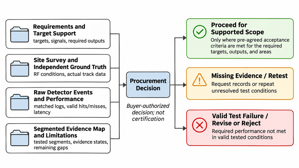
The buyer should agree on detection, timing, and false-alarm limits before the trial. A procurement decision then rests on whether the proposed configuration met those limits in the required conditions. Ask the supplier for an evidence package containing:
- Requirements and configuration baseline: Show the protected area, required outputs, and acceptance criteria. Add sensor identifiers, software versions, installation details, and whether the result is RF-only or fused. This defines exactly which setup is under review.
- Target/protocol support register: List the aircraft, firmware, protocols, transmission modes, and Remote ID states the buyer requires. Put supplier claims beside the field results and mark unsupported or still-unverified requirements.
- Site survey and RF baseline: Provide the site plan, antenna height datum and orientation, obstacles, power and network arrangements, and RF measurements from relevant periods. Identify deployment conditions the trial did not represent.
- Planned and actual flights with independent truth: Match each required height, direction, and route to the flight plan and independent position-time records. Include clock alignment and location uncertainty. Mark missing routes untested; a flown route without usable truth remains indeterminate.
- Raw events and validity ledger: Supply sensor logs and the rules used to match alerts with flights. Retain hits, valid misses, timeouts, outages, invalid attempts, and exclusion reasons, each linked to its raw record. A success-only log cannot support the reported detection rate.
- Stratified performance results: Report hit/miss counts, detection timing and timeouts, valid false-alarm monitoring hours, unresolved alerts, and differences across repeat trials. Separate results by the relevant target, altitude, mode, and background conditions. Do not compare vendors where definitions or essential conditions differ.
- Coverage map and evidence legend: For each segment, show its evidence state, valid opportunity counts, and links to the trial records. Use separate views for targets, altitudes, and system modes; keep estimates and untested areas outside the verified layer.
- Limitations and retest triggers: List unsupported targets, untested sectors, inconsistent outcomes, and missing records with an owner and action for each gap. Specify when changes to hardware, firmware, mounting, networking, or the RF environment require review or new trials.
Brochures, screenshots, and edited demonstrations may show what a system claims; they cannot replace independent tracks, raw event logs, and test conditions. Procurement can move forward only for the targets, outputs, and areas that meet the buyer’s agreed criteria. A strong overall detection rate does not excuse a failed critical sector. If key records are missing, request the evidence. If a valid test fails an essential requirement, revise or reject that configuration for the requirement. Missing evidence does not mean permanent product failure. The buyer’s authorized team makes the decision; this checklist is neither certification nor final system acceptance.
Conclusion
For procurement, RF drone detection coverage is supported only where repeated, valid site trials meet the buyer’s agreed requirements. The evidence needs independent ground truth, a full count of test opportunities, and a map showing the tested targets, heights, and conditions. No universal detection rate, latency, false-alarm limit, or repeat count can be set by this framework. The buyer must choose those limits for the project and test the proposed setup against them. Results remain specific to the equipment, routes, altitudes, operating periods, and RF environment tested; they do not replace formal project acceptance.
A maximum-range circle or one successful demonstration cannot prove stable coverage, and one valid miss does not establish a permanent blind spot. Before approval, identify the most important missing target, sector, or record. Assign a retest or evidence request and state the remaining limit in the proposed purchase scope.
Request a Site-Specific Coverage Review
For a site-specific coverage review, send RF SKYPOWER the protected area, altitude layers, and proposed fixed or mobile sensor positions. Include target models and firmware, protocols and transmission states, required alert or location/tracking outputs, operating periods, RF background, and candidate configuration. Attach any flight tracks, event logs, or maps you have, and identify open procurement questions. Mark missing inputs as pending rather than guessing. The review can identify further evidence needs; it does not certify coverage or authorize procurement.