










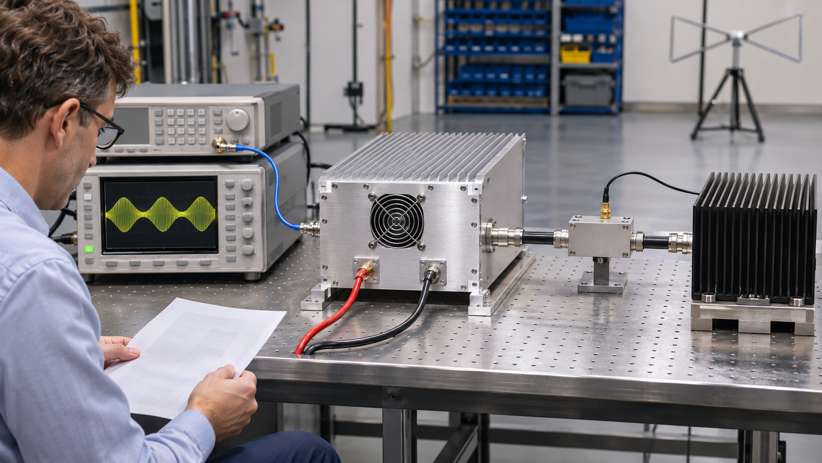
An RFQ for EMC amplifier linear power should specify the minimum output guaranteed to meet the required test waveform and distortion limits. Define whether the wattage represents unmodulated carrier power, modulated average power, peak-envelope power, or pulse-peak power. State the frequency coverage, PA-output reference plane, and operating conditions.
Request output P1dB separately. Include saturated power (Psat) when relevant, with its measurement method and conditions.
A supplier quoting 200 W Psat does not necessarily offer more usable power than one quoting 150 W P1dB. The figures describe different operating points. Neither tells the buyer how much compliant output is available for a specified EMC immunity test.
Establish the meaning of each power claim before ranking suppliers by wattage.
1. What Do Rated Power, P1dB, and Saturated Power Actually Mean?
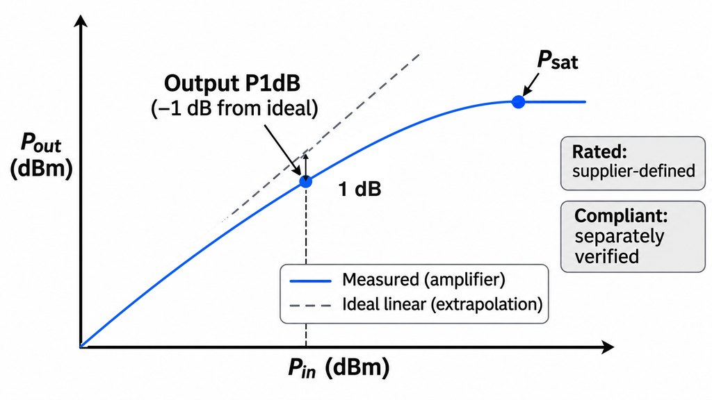
Amplifier datasheets often place several power figures side by side, although each describes a different measurement or operating point.
Rated power follows the supplier’s definition. It may refer to nominal CW output, a particular thermal condition, or another stated rating. Buyers need that definition before using the number in an EMC power calculation.
Output P1dB identifies a gain-compression point. As RF input drive increases, the amplifier eventually produces less output than its small-signal gain would predict. Output P1dB is the output power at the input drive where measured gain has fallen by 1 dB from its small-signal value.
This is a useful large-signal measurement. Distortion, however, can already be present at the 1 dB compression point.
Saturated power, or Psat, describes output near the maximum reached under a specified drive and measurement method. Practical definitions can differ between suppliers. Near saturation, increasing the input drive produces little additional output, while compression and distortion may become more significant.
Compliant usable output addresses the buyer’s actual requirement: the power available while the amplifier meets the specified waveform, linearity, and spectral limits.
| Power metric | Measurement definition or operating point | What it can support | What it does not prove | RFQ treatment |
|---|---|---|---|---|
| Rated power | Supplier-defined output rating under stated conditions | Initial screening when the rating basis is clear | A universal linear-output guarantee | Request the waveform, frequency coverage, conditions, and guarantee status |
| Output P1dB | Output power where measured gain is 1 dB below its small-signal gain | A defined compression operating point | Distortion-free output or compliant AM performance | Request output P1dB versus frequency, with measurement conditions |
| Psat | Output near the maximum reached under a stated drive and measurement method | High-drive output characterization | Continuous linear output or compliance with waveform limits | Report separately when relevant |
| Compliant usable output | Output meeting the specified waveform and acceptance limits under defined conditions | The primary RFQ power requirement when supported by a guarantee and evidence | Performance outside those stated conditions | Specify a guaranteed minimum, power basis, reference plane, and supporting measurements |
The guarantee status deserves a separate check.
A typical curve may reflect one sample or a reference measurement. It does not establish a minimum for every production unit. A guaranteed minimum requires a stated scope and the conditions under which the supplier commits to meeting it.
Before comparing quotations, ask for the definition, measurement point, waveform, and guarantee status of each power figure. Hold any comparison that depends on an undefined rating.
2. Which Power Rating Fits the Required EMC Test Waveform?
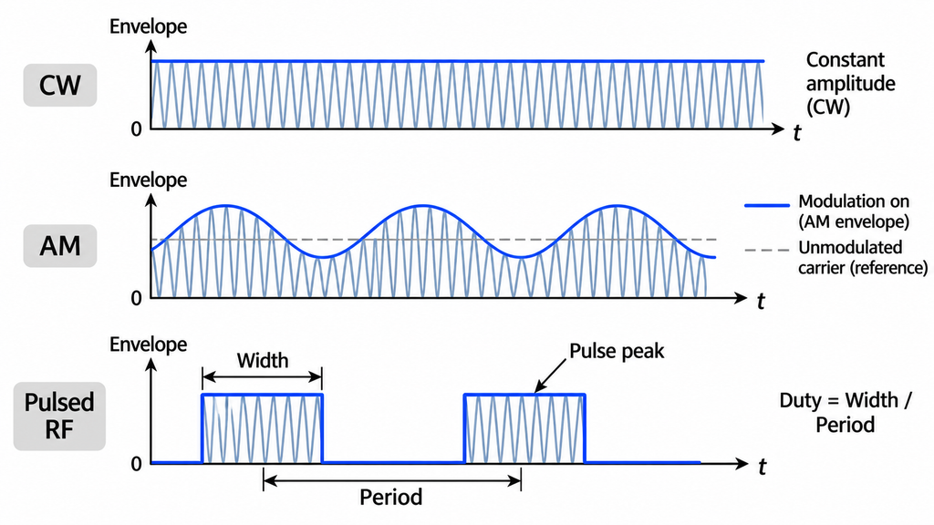
Choose the power requirement from the governing test specification and waveform.
IEC 61000-4-3 is a radiated RF immunity test method, but EMC projects can have different test levels, signal conditions, and acceptance requirements. Use the specification and edition that apply to the project.
For CW operation, request the minimum continuous output at the defined PA-output reference plane. Include frequency coverage, operating duration, thermal conditions, and relevant spectral limits. A short-duration maximum does not establish sustained CW capability.
For amplitude modulation, define the carrier level, modulation depth, modulation frequency, and required waveform fidelity. The RFQ must identify which power quantity the wattage refers to.
Some test methods define a reference power using the unmodulated carrier. If that applies, specify the measurement with modulation disabled. Keep that result distinct from the modulated average power measured while AM is enabled.
The supplier must also demonstrate the required waveform performance with modulation applied. A CW P1dB measurement cannot establish that performance on its own.
For pulsed RF operation, specify pulse-peak power, pulse width, repetition rate, and duty cycle. Add pulse droop or other waveform criteria when the test requires them. A brief pulse peak is not equivalent to continuous output at the same wattage.
For radiated immunity work, field calibration and amplifier-linearity checks help establish the required operating point. The RFQ should retain the test method’s actual power definition instead of substituting a generic catalog rating.
If the test method or waveform remains undecided, the buyer cannot yet finalize the primary guaranteed-power requirement.
3. How Do Modulation Depth and Harmonic Limits Change Usable Power?
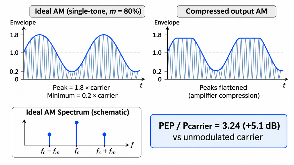
An average power reading can look acceptable even when an amplifier compresses the peaks of an AM envelope. Check power and waveform quality at the same operating point.
Consider ideal single-tone amplitude modulation at 80% modulation depth.
The peak envelope amplitude is 1.8 times the unmodulated carrier amplitude. At the same reference impedance, the relationship is:
PEP / unmodulated carrier power = (1 + 0.8)² = 3.24
That equals approximately +5.1 dB relative to the unmodulated carrier power.
The reference matters. This calculation compares peak-envelope power with unmodulated carrier power. Modulated time-average power is a different quantity, as is the peak-to-average power ratio of the modulated waveform.
The +5.1 dB figure also provides no universal amplifier backoff or procurement margin. Those depend on the waveform and the required acceptance limits.
An amplifier can compress the AM peaks while its average output remains within the expected range. Output P1dB alone cannot show whether the complete envelope is reproduced accurately.
Harmonics and spurious emissions require attention at the intended output level. Their acceptance limits depend on the governing test method, and measurements taken at low drive may not represent high-power operation.
Ask the supplier for waveform and spectral results at the specified output. The report should identify the measurement reference plane, operating power, relevant corrections, and applicable limits.
With only CW P1dB data, the required modulated output remains unverified. Request measurements using the actual waveform and operating point before accepting the claim.
4. Why Does the RFQ Need Guaranteed Power Across the Frequency Band?
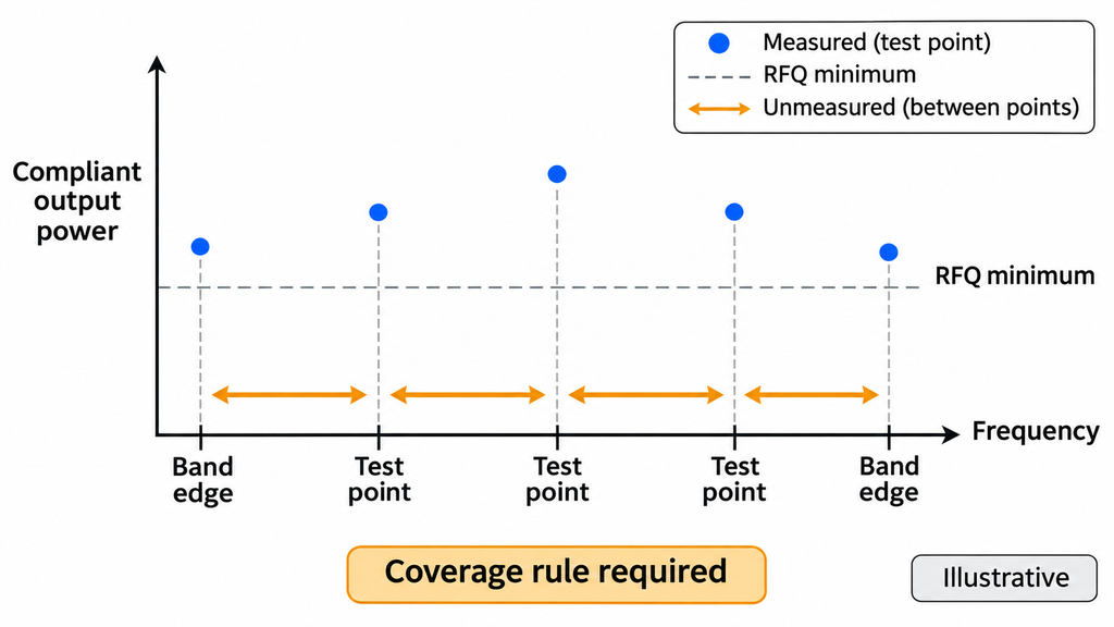
An amplifier may meet the required power at the center of its frequency range and fall below it near a band edge.
Gain, compression, and distortion can vary with frequency. The RFQ therefore needs a defined frequency-coverage commitment.
For continuous-band coverage, the supplier guarantees performance throughout the stated range. For discrete-frequency coverage, the commitment applies to an agreed set of test frequencies.
In either case, identify the verification frequencies, including band edges and other critical points. Choose the grid for the application and the agreed evidence method; there is no universal spacing that suits every RFQ.
A continuous-band guarantee needs an additional rule. The buyer and supplier must agree on how measurements support performance between recorded frequency points. Without that rule, the test record supports only the frequencies and conditions actually measured.
The main evidence should show frequency-resolved compliant output under the required waveform and distortion limits.
Request output P1dB(f) and, where relevant, Psat(f) as separate curves. They help characterize the amplifier but cannot establish the compliant-output guarantee without the corresponding waveform and spectral evidence.
Guarantee status must also be explicit. A typical P1dB curve at selected frequencies cannot become a guaranteed minimum merely because it appears in a quotation.
A swept-frequency full-power RF PA test can show how output changes across the frequency range under recorded conditions. For EMC acceptance, the results must also address the required waveform and spectral criteria at the intended output levels.
Before accepting a continuous-band claim, confirm the guaranteed minimum, frequency limits, verification grid, and evidence-coverage rule. If the evidence supports only selected frequencies, keep the remaining coverage unverified.
5. Which Operating Conditions Must Accompany the Power Specification?
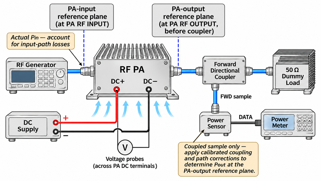
A guaranteed power figure needs a defined measurement plane and operating envelope.
Start with the PA-output reference plane. Identify the amplifier output connector or another explicitly agreed plane.
Power at that point differs from power reaching the antenna after cables, connectors, filters, or switching components. The RFQ must make clear which location the guaranteed wattage applies to.
Specify the measured power quantity as well.
Under a matched load, corrected forward power at the PA-output reference plane may be an appropriate rating. With a mismatched load, forward power and net power delivered to the load are different quantities.
If mismatched-load performance forms part of acceptance, define the load condition and any required reflection-phase coverage. A VSWR magnitude alone may not describe every relevant load condition.
The RFQ must distinguish normal output performance from protection behavior.
First, specify the output the amplifier must deliver under the agreed operating and load conditions. Then define the permitted response when reflected power or VSWR exceeds a protection threshold.
A protective reduction or shutdown can be the correct response to a fault. It does not establish that the normal power guarantee remains satisfied while protection is active.
Input drive and DC supply measurements also affect the result.
Actual Pin means the RF input power at the defined PA-input reference plane. The signal generator setting may differ because of cables, attenuators, couplers, and other path losses. Account for applicable corrections when determining the actual drive.
Specify DC voltage at the amplifier terminals. A voltage measured only at the power supply output may overlook losses in the supply wiring. Do not assume that every amplifier uses the same DC voltage or cooling arrangement.
Record the remaining acceptance conditions:
- Ambient temperature and relevant case, baseplate, or cooling conditions.
- Cooling configuration and airflow or liquid-cooling requirements, where applicable.
- Cold-start or thermally stabilized operation.
- Continuous duration, pulse timing, or duty cycle.
- Load impedance, VSWR, and permitted protection state.
- Measurement method, corrections, and uncertainty.
A short cold-state test cannot establish a sustained hot-state guarantee without supporting evidence.
Agree on the treatment of measurement uncertainty and any acceptance guard band before evaluating results close to the specification limit.
The scope of the tested hardware matters, too.
A module-level power report does not, by itself, verify a completed amplifier assembly. The final power supply, cooling configuration, output interface, and operating conditions must remain within the evidence-supported scope.
If the RFQ covers an integrated amplifier, request test records or a documented technical justification showing how the evidence applies to that configuration. A result obtained from a module on a laboratory fixture should not automatically be treated as an assembly-level guarantee.
With the output basis established, the project’s RF PA power-margin calculation can account for the required system margin. An added margin cannot correct an undefined reference plane or unsupported output rating.
If a quotation omits a condition that affects acceptance, request the matching test record or clarification before comparing it with another supplier’s result.
6. How Can Buyers Compare Two Supplier Power Claims?
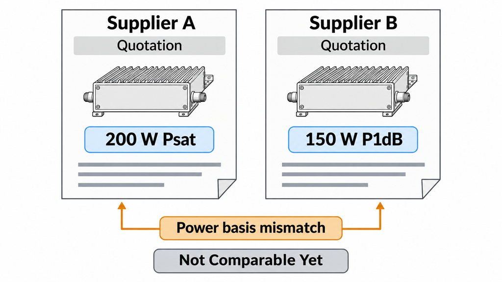
Two quotations become comparable when their power definitions and supporting test conditions align.
Check the waveform, frequency coverage, reference plane, Actual Pin, DC supply, load, thermal state, measurement method, uncertainty treatment, and guarantee level.
Classify the evidence into three states.
Comparable
Both suppliers report the required power quantity under sufficiently aligned conditions. Their evidence covers the relevant frequencies, waveform, and acceptance limits.
The buyer can compare the supported values directly with the RFQ minimum.
Partially Comparable
Some measurements align, while another requirement remains unverified.
For example, two suppliers may provide comparable P1dB curves, but only one submits AM waveform measurements at the specified output. The P1dB comparison can proceed. The comparison of guaranteed AM-compliant output must wait for the missing evidence.
Record which dimension is supported and what the supplier still needs to provide.
Not Comparable Yet
The suppliers quote different power quantities, or decisive operating conditions are unknown.
Ask for matching definitions and measurements. A conversion between incompatible ratings is unreliable without evidence supporting that conversion.
Missing documentation leaves the procurement decision open; it does not establish that the product would fail the test.
Identify the evidence gap and give the supplier an opportunity to address it. Keep the affected comparison open until the response supports a decision.
RFQ: How to Specify Linear Power and Saturated Power
Use minimum guaranteed compliant output as the primary contractual power figure. Report output P1dB and Psat separately.
For this RFQ, compliant output means amplifier output that meets the stated power, waveform, and spectral acceptance criteria at the defined PA-output reference plane. It does not establish compliance of the complete immunity test chain or the EUT.
The power measurement state must also be clear. An unmodulated carrier reference may be measured with modulation disabled, while waveform fidelity is checked after modulation is enabled.
Use this clause as a project-specific template. Complete or explicitly agree on every bracketed requirement before acceptance.
Proposed EMC Amplifier RFQ Power Clause
The amplifier shall deliver a minimum guaranteed compliant output of [X W or Y dBm], defined as [unmodulated carrier power / modulated average power / peak-envelope power / pulse-peak power, as applicable], at [specified PA-output reference plane] over [required frequency range or test points, verification frequency grid, band-edge points, and evidence coverage rule].
The power quantity shall be measured under [defined power measurement state: modulation disabled or enabled, or specified pulse measurement window]. The required waveform and spectral performance shall be verified under [specified signal operating state], according to [test specification, method, and edition] using [waveform, modulation parameters, pulse timing where relevant, and duty cycle].
At the specified operating output, the amplifier shall meet [linearity, waveform-fidelity, harmonic, and spurious limits] under [Actual Pin range at the PA-input reference plane, DC supply condition at the amplifier terminals, load or VSWR, cooling configuration, ambient and stabilized thermal state, and operating duration].
The supplier shall provide frequency-resolved compliant-output evidence and an explicit minimum guarantee covering the agreed frequency and operating conditions. For any continuous-band guarantee, the supplier shall explain how its evidence supports performance between recorded frequency points.
Output P1dB(f) and, where relevant, Psat(f) shall be reported separately, with their measurement definitions and typical or guaranteed status. These curves shall not substitute for evidence supporting the primary compliant-output requirement.
The report shall identify [measurement method, power quantity, reference planes, measurement corrections, uncertainty, acceptance decision rule, and report scope]. The supplier shall state whether the evidence covers [a representative sample, defined batch, or each delivered unit]. Where required, mismatched-load behavior and permitted protection responses shall follow [separately defined test conditions and acceptance criteria].
Record the evidence requirements alongside the clause so that every supplier responds to the same specification.
| RFQ item | Buyer-defined requirement | Supplier evidence | If missing |
|---|---|---|---|
| Test method and waveform | Specification and edition; CW, AM, or pulse conditions; modulation, duty cycle, and measurement state | Declared test basis and corresponding records | Keep waveform-dependent claims open |
| Frequency coverage | Band or discrete points; verification grid, band edges, and coverage rule | Frequency-resolved results and guarantee scope | Do not infer unsupported frequency coverage |
| Primary compliant output | Minimum guaranteed W or dBm; explicit power basis and PA-output reference plane | Minimum guarantee and compliant-output results under required conditions | Do not substitute rated power, P1dB, or Psat |
| Linearity and spectral limits | Required waveform fidelity, harmonics, spurious limits, and operating point | Measurements using the specified waveform at the intended output | Hold the compliant-output decision |
| Output P1dB | Reporting frequencies and operating conditions | Output P1dB(f), definition, and guarantee status | Request compression evidence |
| Psat, where relevant | Measurement definition, frequencies, and drive conditions | Psat(f) and corresponding method | Keep the supplementary metric unreported |
| RF drive and DC supply | Actual Pin at the PA input and voltage at amplifier terminals | Recorded input and supply conditions | Request condition-matched evidence |
| Load, cooling, and duration | Load/VSWR, thermal state, cooling, duty or duration, and separate protection criteria | Test conditions and relevant protection records | Do not extend matched-load or cold-state results |
| Measurement and uncertainty | Power quantity, reference plane, calibration, corrections, uncertainty, and decision rule | Traceable measurement record | Resolve the measurement basis before acceptance |
| Guarantee and report scope | Minimum guarantee; sample, batch, or per-unit coverage | Supplier commitment and reports matching that scope | Do not infer delivery-wide coverage from one sample |
If the buyer requires a report for every delivered amplifier, the RFQ must say so explicitly. A representative-sample test and a serial-number-specific report provide different levels of delivery evidence.
RF SKYPOWER’s RF power amplifier module families provide frequency-range and nominal-power starting points for standard or customized solutions. A listed power class remains a candidate for this RFQ until the required compliant output and operating conditions have supporting evidence.
Conclusion: Which Power Number Should Go in the RFQ?
Use the minimum guaranteed compliant output power as the main RFQ figure. Tie it to the required waveform, power measurement basis, frequency coverage, PA-output reference plane, and operating conditions.
Request output P1dB independently. Add Psat when that measurement helps characterize the proposed amplifier.
Before shortlisting, send every supplier the same completed RFQ. Require a stated minimum guarantee and evidence that covers the agreed frequencies, waveform, measurement conditions, and report scope.
For an RF SKYPOWER engineering review, provide the test method and edition, power basis, frequency grid, modulation or pulse requirements, distortion limits, expected RF input drive, DC supply, load, cooling, thermal state, operating duration, and measurement requirements.
These details allow the engineering team to evaluate potential standard modules or customized amplifier configurations and identify any additional tests required for acceptance. An individual model’s EMC performance remains subject to evidence under the agreed conditions.