










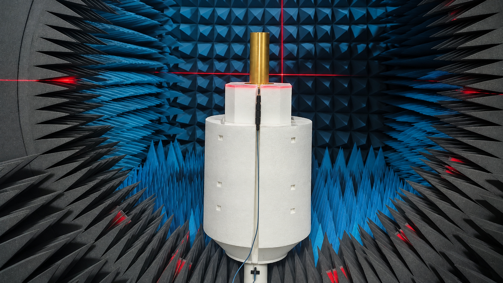
Omnidirectional antenna gain should be verified at the required frequencies and angles using a calibrated measurement method, defined gain metrics, and a documented uncertainty budget.
“Omnidirectional” describes coverage around the antenna in a specified plane. It does not mean equal gain in every direction in three-dimensional space. A single catalog value also leaves a basic purchasing question open: is that number typical, the highest measured value, or a guaranteed minimum?
Before comparing antennas, establish what the quoted number represents. A higher figure can reflect different test conditions rather than better performance for the project.
RF SKYPOWER Omnidirectional Antenna Options
RF SKYPOWER offers standard wideband omnidirectional antennas for different frequency ranges and installation requirements. The models below provide a starting point for selection. Final acceptance should be based on the specified gain definition, frequency-dependent measurements, radiation patterns, and agreed test conditions.
| Model / PDF | Frequency Range | Maximum Rated Power | Dimensions |
|---|---|---|---|
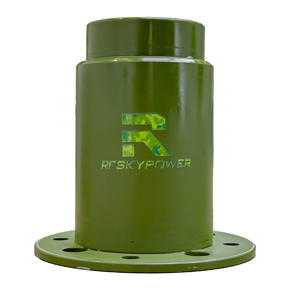 HZA8002600-OD1Mid-band omni antennaOpen PDF ↗ | 800–2600 MHz | 250 W max. | Ø90 × 120 mmØ140 mm flange |
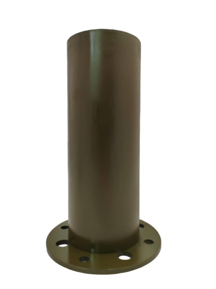 HZA3803000-OD1Omni cylinder antennaOpen PDF ↗ | 380–3000 MHz | 250 W max. | Ø90 × 240 mmØ145 mm flange |
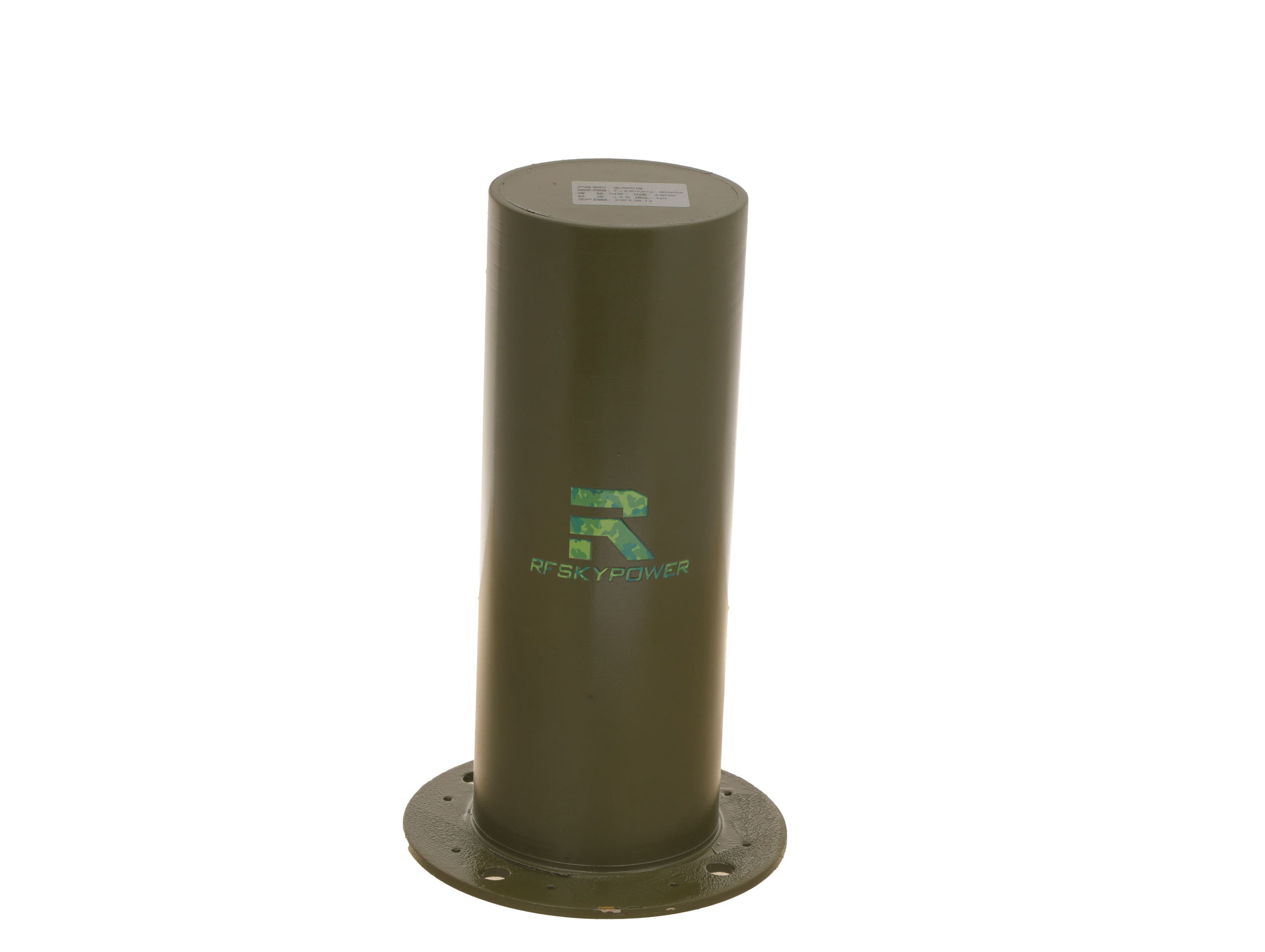 HZA4006000-OD1High-band omni antennaOpen PDF ↗ | 400–6000 MHz | 250 W max. | Ø90 × 240 mmØ145 mm flange |
Swipe horizontally to compare all three antenna configurations →
These are standard product references, not the limits of RF SKYPOWER’s manufacturing capabilities. Custom antenna configurations can also be discussed for project-specific frequency coverage, mounting arrangements, and performance requirements. Explore our wideband antenna range for further details.
Before comparing gain figures across these models, the first step is to establish what each published gain claim actually means.
1. What Does an Omnidirectional Antenna Gain Claim Actually Mean?
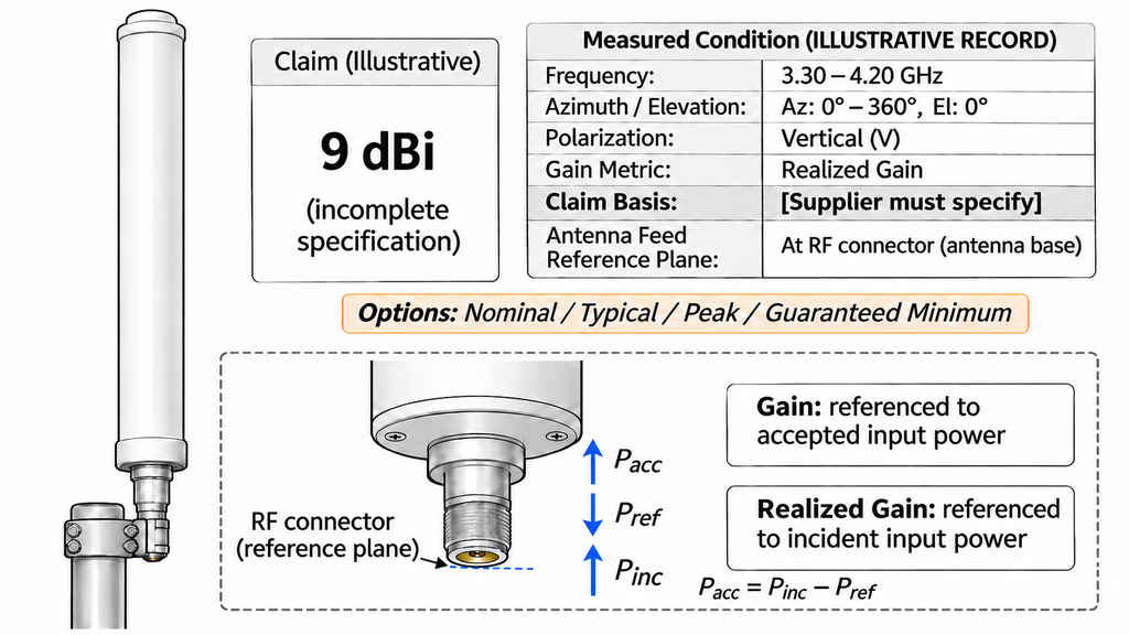
A gain claim needs both a value and a defined scope. “9 dBi,” for example, does not identify the frequency, direction, polarization, or conditions behind the number.
The qualifier changes what the supplier is claiming:
- Nominal gain is a supplier-defined reference or design figure. The label alone establishes neither a statistical basis nor a guaranteed lower limit.
- Typical gain describes expected performance under stated conditions. It is not automatically a guarantee for every antenna.
- Peak gain identifies the maximum over a defined search range, such as the measured directions at one frequency.
- Minimum gain can serve as a guaranteed lower bound only when the specification defines its frequency, angular, polarization, and operating conditions and commits to that limit.
A report must also identify the gain reference. dBi uses an isotropic radiator; dBd uses a half-wave dipole. Under otherwise comparable conditions, gain in dBi is approximately 2.15 dB higher than gain in dBd. A value written only in dB leaves the reference unresolved. Ask the supplier to clarify it before comparing values.
Gain and realized gain use different power references
Gain relates radiation in a specified direction to the power accepted by the antenna. It includes radiation efficiency. Realized gain uses incident power at the stated antenna port reference and includes impedance mismatch under the specified reference conditions.
A gain value with mismatch removed should not be ranked directly against realized gain with mismatch included. Neither term automatically includes external feeder loss or the polarization mismatch between a transmitting and receiving antenna.
Confirm whether the reported quantity is total gain or a specified polarization component. The reference impedance, antenna port, and treatment of any attached cable must also be clear.
For an omni antenna, broad azimuth coverage usually applies at a specified elevation relative to the mounting axis. Gain can vary around that plane and change substantially above or below it. For C-UAS applications, choosing between horn, omni, and multi-port panel antennas sets the coverage architecture; it does not establish whether the chosen antenna meets a full-band gain requirement.
A usable gain requirement names the metric and unit, minimum value, frequency range, angular region, and polarization. A supplier claim that cannot be mapped to those conditions is not ready for comparison.
2. Which Frequencies Must Be Included in the Gain Test?
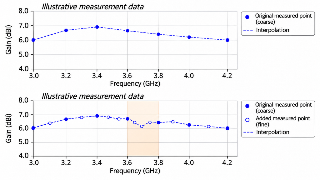
The test frequencies should come from the project’s operating needs and the way antenna performance changes across the band. There is no single frequency spacing that proves every wideband omnidirectional antenna suitable for every application.
Include the lower and upper band edges, important operating frequencies, and each required sub-band. Pay particular attention to sub-band transitions and areas where existing curves suggest rapid change or a possible gain dip.
An initial dataset can help identify where closer sampling is needed. A narrow dip may fall between widely spaced points, even when the plotted line looks smooth. Simply joining those points does not add measurement evidence between them.
The report needs the actual test-frequency list, not only the stated operating band. Sampling density should reflect measured variation and project risk. Interpolation can describe a trend, but it cannot establish minimum gain between points without supporting evidence. Critical frequencies in an unsupported interval need additional measurements.
Supplier comparisons must use the same required frequencies and compatible angular conditions. Two reports may be comparable at their common measured points without supporting a comparison across the whole band. A sparse report should not appear better merely because it omits the frequencies where performance changes most.
The project frequency list should identify each required point and explain where closer sampling is needed. Any unsupported interval remains open in the full-band acceptance review.
3. How Is Gain Measured on a Calibrated Antenna Range?
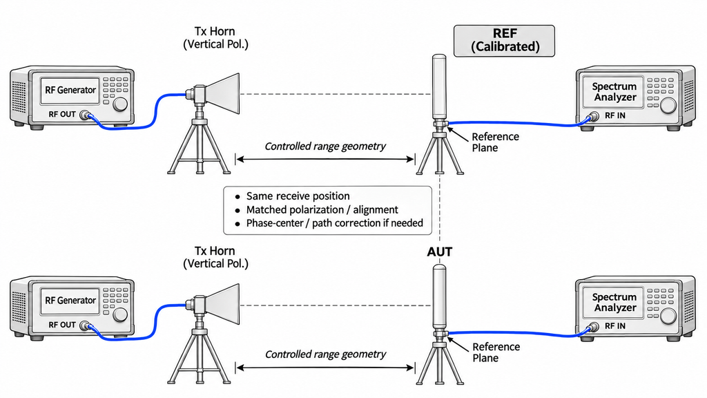
An absolute gain result needs a traceable measurement basis. A photograph of an anechoic chamber, a VNA trace, or a transmission reading alone does not establish that basis.
In a gain-transfer or substitution measurement, a reference antenna with known gain provides the comparison. The test relates the antenna under test to that reference under controlled conditions. The reference calibration must apply to the frequencies, polarization, and antenna configuration being used.
The range must also suit the measurement. Distance, alignment, antenna position, reflections, and polarization can change the received signal. Replacing the reference antenna must not introduce an unexplained change in geometry or the measurement path. The report should explain how the method controls or removes propagation-path loss rather than treating a received-power reading as gain.
A usable method statement identifies the reference antenna and calibration record, measurement geometry, and reference planes. The reported gain must account for applicable cable and adapter losses, mismatch, and other corrections under the stated gain definition.
For example, a result referenced to the end of an attached cable describes a different measurement boundary from one referenced to the antenna connector. Moving the result between those planes requires corrections consistent with the gain definition, including relevant cable attenuation and mismatch effects. Subtracting nominal cable loss alone may not be sufficient. The report must state the corrections, without omitting or counting losses twice.
VSWR cannot prove antenna gain. It describes impedance matching at the measurement reference plane. It does not independently establish radiation efficiency or the distribution of radiated power. An uncalibrated transmission measurement likewise cannot automatically become an absolute gain result.
Other valid methods, including suitable near-field measurements transformed to far-field results, may also support gain data. Different methods can produce comparable results when their definitions, reference conditions, corrections, and uncertainty are compatible.
Without a traceable calibration chain, the data may still support a limited relative comparison. They cannot establish the claimed absolute gain or justify acceptance.
4. Why Must Azimuth and Elevation Patterns Both Be Checked?
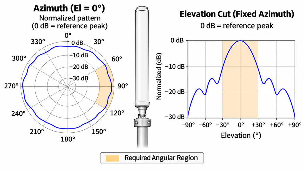
A horizontal pattern answers where energy goes around the antenna at a defined elevation. An elevation pattern shows how that distribution changes above and below the chosen reference direction. Both matter when the required directions extend beyond a single horizontal slice.
At each relevant frequency, review the full 360° azimuth cut and the elevation cuts needed for the application. Identify the coordinate origin, mounting orientation, fixed angle for each cut, and measured polarization. A label such as “horizontal pattern” is not enough if the underlying orientation remains unclear.
Inspect the low points as well as the peaks. A favorable maximum can coexist with a lower gain in a required direction. Angular sampling also matters: coarse samples may miss a narrow dip between points.
A normalized pattern does not provide an absolute gain value
A normalized plot shows relative levels against its chosen reference. If each pattern is normalized to its own peak, similar-looking curves can have different absolute gains.
To use that plot for an absolute minimum-gain requirement, obtain the matching absolute gain reference. It must correspond to the same frequency, polarization, gain definition, and normalization basis. Do not attach a catalog peak from another condition to the plotted shape.
Compare patterns only after their axes, polarization, angular sampling, and normalization are aligned. Data from one frequency cannot replace missing cuts at another, and several two-dimensional cuts do not establish a complete three-dimensional dataset.
The required angular region must map to measured cuts at the relevant frequencies. Missing directions need additional pattern measurements; normalized cuts also need a matching absolute gain reference. Even a complete laboratory pattern cannot establish communication or detection distance at an installed site.
5. How Do Gain Flatness and Azimuth Ripple Differ?
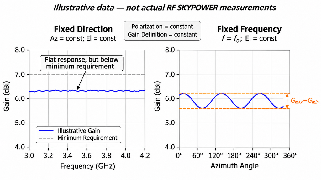
Gain flatness and azimuth ripple describe variation along different axes. A supplier’s claim about one cannot establish the other.
Gain flatness: change frequency while holding direction fixed
For a fixed-direction gain-flatness assessment, hold azimuth, elevation, polarization, and the gain definition constant. Then examine gain across the specified frequency range.
The result shows whether that direction retains the required performance as frequency changes. Define the statistic as well: a maximum-to-minimum spread is different from a tolerance stated as ±dB around a named reference value.
A flat curve can still sit below the required minimum. Flatness therefore supplements the absolute gain requirement; it does not replace it.
Azimuth ripple: change direction while holding frequency fixed
Azimuth ripple describes gain variation around the antenna at one frequency, with elevation and polarization held constant. Its scope must identify the angular range and whether the value is a peak-to-peak spread or another defined measure.
An antenna can have small frequency variation in one direction yet show a significant dip elsewhere in the azimuth cut. Conversely, a fairly uniform azimuth pattern at one frequency says little about gain flatness across the band.
Identify what each plotted curve actually represents
Taking the highest gain at each frequency produces a valid peak-gain-versus-frequency curve when it is labeled that way. The direction of that peak may move with frequency.
Such a curve cannot prove gain in a fixed direction. It also cannot establish the minimum across a required angular region. An angular minimum or average can be useful too, but the report must name the region, samples, and calculation used.
The specification needs separate definitions for flatness and ripple, including the changing variable, fixed conditions, and calculation. When a report omits those details, its curves cannot be compared with another supplier’s until the underlying frequency–angle data are available.
6. How Should Measurement Uncertainty Affect Acceptance?
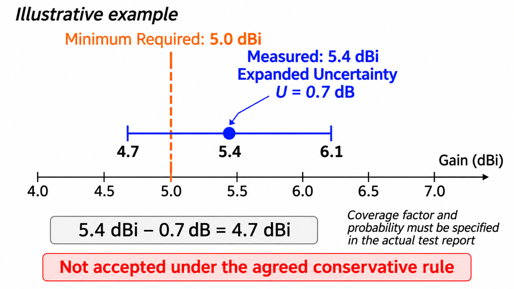
A measured gain slightly above a minimum limit does not, by itself, settle acceptance. The decision also depends on the measurement uncertainty and the rule agreed for using it.
Relevant uncertainty sources can include the reference antenna’s calibration, range reflections, alignment, positioning, connector repeatability, and antenna remounting. Their effect may vary with frequency or configuration. Request a budget summary identifying the principal contributors, how they were combined, and the frequencies, directions, polarization, and test setup covered by the reported uncertainty. An unexplained single value cannot be assumed valid across the entire band.
The report should identify standard or expanded uncertainty. For expanded uncertainty, it also needs the coverage factor and associated coverage probability or confidence statement. Two reports may use different uncertainty expressions, and the coverage factor alone does not fully define them.
One possible conservative acceptance rule for a minimum-gain requirement is:
G_measured − U ≥ G_required
Here, both gain values use the same reference, such as dBi. U is an applicable uncertainty expressed as a dB difference, with its type and coverage information defined. The project must agree to this rule and its treatment of U before using it for acceptance.
For illustration only, suppose a project requires 5.0 dBi. An example result is 5.4 dBi with an expanded uncertainty of 0.7 dB under the agreed conditions. Subtracting U gives 4.7 dBi. Under this conservative rule, the result cannot receive a pass.
That does not automatically prove the antenna’s true gain is below 5.0 dBi. The agreed decision rule determines whether the outcome requires further evidence, retesting, or a stated acceptance decision. The example values are hypothetical and are not RF SKYPOWER test data.
The formula is a project-specific guard-band option, not a mandatory antenna-testing rule. Borderline handling belongs in the purchase specification. If suppliers use different rules or uncertainty expressions, compare their measurements on a common basis rather than ranking their “pass” labels.
7. What Changes When an Omnidirectional Antenna Is Installed?
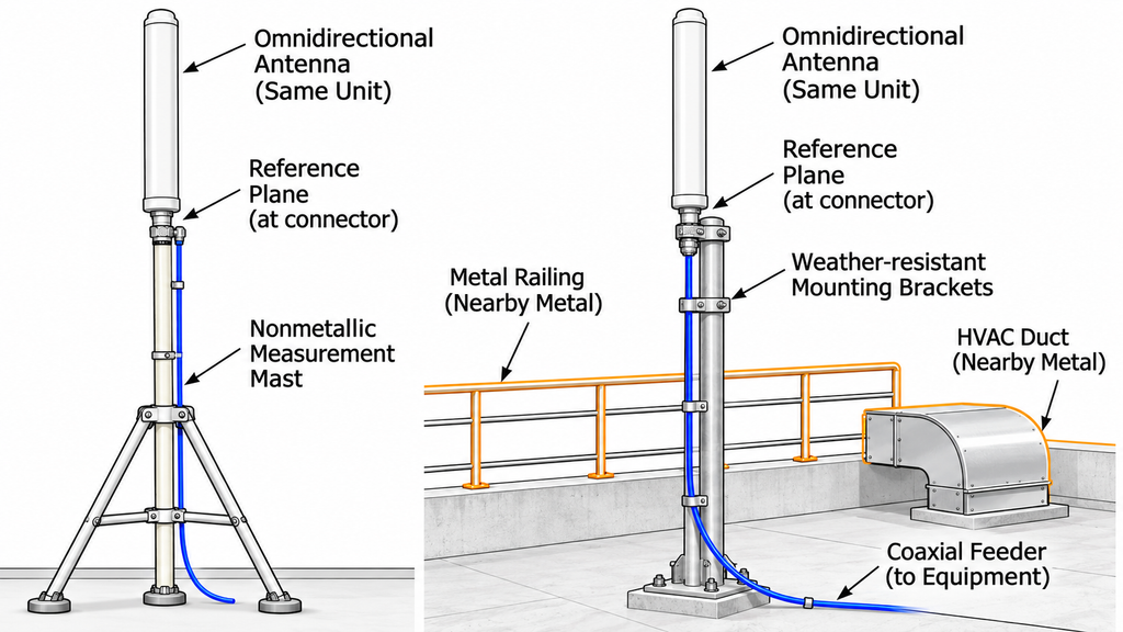
Laboratory results apply to the configuration tested. A mast, vehicle body, ground plane, bracket, or nearby metal can alter the installed pattern. Cable routing can also matter if it affects unwanted common-mode currents.
Separate those effects from feeder attenuation. Cable loss reduces the power reaching the antenna; it is not automatically a change in the antenna’s own gain. Installation height can change propagation and coverage without changing intrinsic antenna gain.
The report’s mounting orientation, support structure, ground plane, and cable arrangement should match the intended installation or show exactly where they differ. Significant changes may require configuration-specific verification. Unknown installation conditions or reference planes leave installed performance unproven.
The system EIRP calculation also depends on power and RF-path losses at defined reference planes, together with the applicable antenna gain. Laboratory gain alone establishes neither system EIRP nor field coverage. Those system judgments require their own inputs and evidence.
8. What Must the Supplier’s Gain Report Include Before Approval?
A supplier’s gain report supports approval only when its results map to purchasing requirements under matching conditions. Before interpreting the plots, establish the antenna model and revision, tested sample, report revision, and scope of the conclusions.
The measurement method, calibration references, antenna reference plane, and relevant cable or adapter corrections should all be traceable. Any deviation from the agreed method, missing report page, or absent data file needs resolution before the report can support approval.
Full-band gain acceptance matrix
Each matrix row pairs a project requirement with its measurement and evidence source. Use enough rows to cover every required frequency and angular condition; the prompts are placeholders for actual requirements and report values.
Identify whether a row refers to one direction or the minimum over a defined angular region. For a regional minimum, the supporting data must state the angular samples and how gaps between them are addressed. Do not substitute peak gain for that minimum.
Use a stated gain reference for requirements and results. Express uncertainty in compatible dB terms and identify its coverage information, either in the cell or an unambiguous linked report record. Complete the following report context before filling the matrix:
Report context: Model / revision: [enter] · Sample ID: [enter] · Report ID / revision: [enter] · Method / calibration reference: [enter] · Antenna reference plane: [enter] · Agreed decision rule: [enter].
| Test frequency | Azimuth / elevation condition | Polarization | Minimum required gain | Gain definition | Measured result | Measurement uncertainty | Acceptance decision | Evidence ID |
|---|---|---|---|---|---|---|---|---|
| Lower edge: [frequency] | [angle / region] | [polarization] | [limit / unit] | [gain type / component] | [report value] | [U / coverage] | [decision under rule] | [report / data ID] |
| Key operating point: [frequency] | [angle / region] | [polarization] | [limit / unit] | [gain type / component] | [report value] | [U / coverage] | [decision under rule] | [report / data ID] |
| Transition or suspected dip: [frequency] | [angle / region] | [polarization] | [limit / unit] | [gain type / component] | [report value] | [U / coverage] | [decision under rule] | [report / data ID] |
| Upper edge: [frequency] | [angle / region] | [polarization] | [limit / unit] | [gain type / component] | [report value] | [U / coverage] | [decision under rule] | [report / data ID] |
Four sample rows do not define a universal test grid. Missing evidence remains an open request, not a measured failure.
The review should lead to one of three outcomes:
- Evidence is complete and meets the agreed requirements. Record approval within the stated model, sample, configuration, and test scope.
- Evidence is insufficient. Identify the exact frequency, angle, definition, calibration, uncertainty, or report-scope gap and request clarification or additional testing.
- Comparable evidence does not meet the agreed requirements. Record the unmet criterion and the decision rule used, without extending that result beyond the evaluated scope.
A representative sample report does not establish that every delivered antenna has passed the same tests. If the purchase requires unit-linked evidence, specify the tested parameters, frequencies, angles, unit identifiers, and report linkage in the contract. For batch sampling, define the sampling scope and what it supports. A serial number alone does not prove a complete gain test was performed on that unit.
With the required conditions defined in the matrix, buyers can identify candidate designs in the RF SKYPOWER antenna catalog and request matching gain evidence. Requirements not covered by the listed configurations can be reviewed for possible customization; feasibility and the associated test scope must still be confirmed.
Conclusion
Approve an omnidirectional antenna gain claim only within the frequency and angular range supported by comparable data. The gain definition, measurement method, reference conditions, and uncertainty must support the project’s agreed acceptance rule.
This framework does not set a universal minimum-gain limit or replace model-specific evidence. Typical and peak values are not guaranteed minima. Laboratory results cannot establish installed system performance, and a sample report does not approve a delivery batch.
Complete the acceptance matrix and mark the conditions the report does not cover. Those gaps become specific requests for data, clarification, or retesting. Agree how borderline results will be judged before approving the claim.
For a technical RFQ, send RF SKYPOWER your antenna requirements with the completed matrix and any available reports. Include the operating band, key frequencies, azimuth/elevation region, polarization, gain metric and minimum, and flatness or ripple limits. Describe the mounting orientation, ground plane, nearby metal, connectors, feeder reference plane, power handling, and duty conditions.
The RFQ should also state the required frequency/angle sampling, calibration and uncertainty evidence, acceptance rule, and whether reports must be linked to a representative sample, batch, or individual units. RF SKYPOWER can review listed configurations or discuss customization, but suitability, feasibility, and test scope require confirmation for the proposed design.