










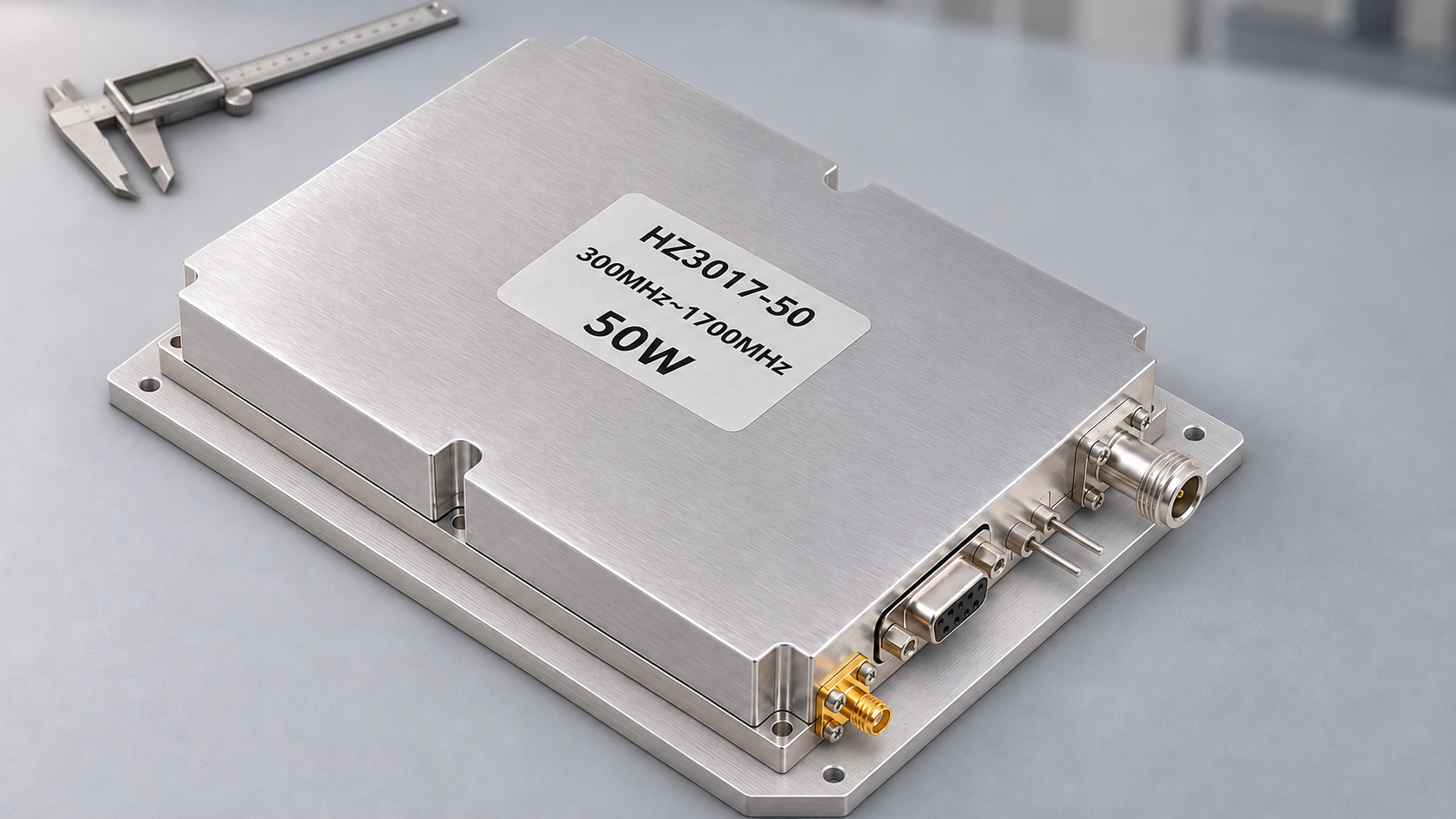
An approved RF power amplifier module is drop-in compatible with a later revision only when the replacement still meets the system’s approved operating and interface requirements, with sufficient evidence for the customer’s change-approval process. The same part number, output-power rating or mounting pattern cannot establish that by itself.
Physical fit, functional compatibility and permission to omit further system requalification are separate decisions. A revised module may fit the enclosure and work with the installed RF chain, power supply, cooling and controller. Approval to use it without requalification still depends on the original approval basis, the revision’s impact and the customer’s rules.
Start with the exact approved configuration. Otherwise, a real change may go unnoticed while a test-method difference may be mistaken for a hardware problem.
1. What Does Drop-In Compatible Mean for an Approved RF PA Module?
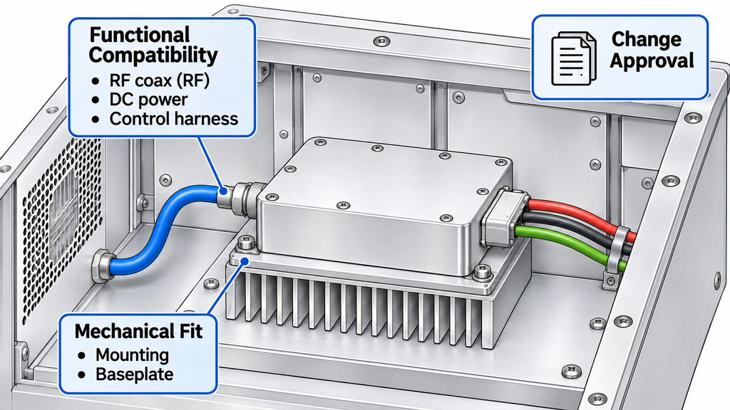
For an OEM project, drop-in compatible means a proposed revision can replace the approved RF PA module within that system’s installation, operating and approval boundaries. The conclusion applies to those conditions, not every installation of the model.
The baseline should identify:
- The approved part number, hardware revision and, where relevant, firmware or control-interface version.
- The controlled mechanical drawing, RF connector definition, DC pinout and command or status map.
- The operating envelope: frequency points, signal type, RF drive, output-power definition, supply at the module terminals, load, duty cycle and cooling arrangement.
- The original verification basis: test procedure and report revisions, applicable limits, approved configuration and the party authorized to accept changes.
Mechanical fit is the narrowest test. A replacement can occupy the same mounting holes while requiring a different supply current or reporting a fault through a changed control state. Functional compatibility is broader: the installed system must still operate within the requirements that were approved. Permission to omit additional requalification is broader still; it depends on the documented change and the customer’s approval rules.
If the original revision or a safety-relevant interface definition cannot be established, hold the compatibility decision until the baseline is recovered.
2. Which Revision Changes Can Break Module Interchangeability?
A supplier revision notice identifies what changed. The buyer then has to connect those changes to the interfaces, operating conditions and approval requirements of the installed system.
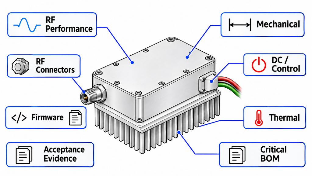
Review changes across eight dimensions. Each dimension needs its own evidence and action; a matching connector cannot compensate for a changed protection response, and a complete document package cannot substitute for a required physical test.
| Change dimension | Approved definition or requirement to compare | Potential system impact | Evidence to request | Next validation or approval action |
|---|---|---|---|---|
| RF performance | Frequencies, drive, gain, Pout metric, spectrum, load | Changed RF-chain margin or behavior | Revision-specific limits and comparable corrected RF results | Check affected operating points; test gaps as required |
| Mechanical | Outline, hole pattern, tolerances, height, baseplate | Fit, mounting stress or thermal contact | Controlled drawings and dimensional change record | Review fit; inspect a sample where needed |
| RF connectors | Type, mating interface, orientation, clearance, rating | Cable mating or RF-path change | Port drawings, mating specification, change record | Verify mating and affected RF path |
| Pinout and control | DC pins, logic levels, enable, commands, status, alarms | Incorrect startup or fault response | Pin map, interface revision, state definitions | Check wiring and controller behavior |
| Thermal boundary | Heat-transfer surface, mounting, cooling, thermal behavior | Hot-state drift or protection action | Thermal-change record and hot-state evidence | Review or retest affected thermal state |
| Firmware, if applicable | Version, timing, status, protection logic | Changed startup or fault recovery | Firmware log and control-state map | Recheck affected sequences and states |
| Bill of materials (BOM) | Critical parts, materials, approved sources | RF, thermal, electrical or protection variation | Controlled BOM impact and qualification evidence | Assess affected paths; define targeted checks |
| Acceptance evidence | Method, conditions, report revision, configuration, lot/S/N scope | Unsupported release or equivalence claim | Report crosswalk, scope and traceability | Request missing records or limit approval scope; evidence gaps are not hardware failures |
Use the matrix to identify the affected requirements and open evidence requests before assigning an approval status. A change can be low impact for one OEM installation and significant for another. Moving an RF connector, for example, may be manageable on an open bench but incompatible with a cabinet’s fixed coaxial cable assembly. A change to RF PA assembly or test processes may leave the external interfaces untouched while changing the evidence needed to assess the revision.
If the revision documentation does not sufficiently identify a change relevant to the approved system, leave the affected dimension unresolved and hold replacement approval until the configuration difference and evidence scope are established.
3. How Should RF Performance Be Compared Across Revisions?
Two revisions may list the same rated output power yet provide RF reports that are not directly comparable. Before interpreting a difference, verify that the numbers describe the same quantity under the same relevant operating conditions.
For each project-required frequency, including critical band edges, align the following:
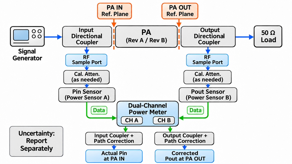
- Actual RF input power (Pin): RF power at the defined PA input reference plane, measured directly or derived from a recorded upstream measurement using a validated input-path correction. The signal-generator setting alone is insufficient evidence of actual Pin.
- RF output power (Pout): compare the same defined output-power quantity at the same PA output reference plane for both revisions. Preserve the raw meter or sensor reading, applicable calibrated coupler and path corrections, and corrected Pout.
- Waveform and timing: continuous-wave, pulsed or modulated operation; applicable duty cycle, measurement window and any required multicarrier condition.
- Electrical and RF load conditions: DC voltage at the module terminals, available current, load or mismatch condition, and the relevant control or protection state.
- Thermal condition: cold-state or stabilized operation, ambient or baseplate measurement point, cooling arrangement and test duration.
- Measurement basis: instrument method, fixture and calibration records. Evaluate and report measurement uncertainty separately from path correction, applying the project’s approved decision rule where relevant.
Compare gain at consistent input and output planes. If efficiency is an approval requirement, use the relevant measured RF and DC quantities under comparable conditions. Spectrum, harmonic or linearity results belong in the comparison when the approved waveform and system requirements make them relevant; nominal output power alone cannot stand in for them.
An RF comparison should end with one of three findings for each parameter:
- Comparable: the measurement definition and material conditions align, and the evidence covers the approved operating point.
- Partially comparable: some frequencies, waveforms, temperatures or other conditions align, but the conclusion is limited to that overlap.
- Not comparable yet: a critical quantity, reference plane, correction or operating state is missing or inconsistent. Request the missing information before declaring improvement, degradation or equivalence.
A comparable Pout result does not automatically validate gain, spectral behavior, thermal performance or protection logic. Similarly, a corrected result at the module RF OUT connector must not be treated as power delivered at a downstream feeder or antenna reference plane.
When the original and replacement reports come from different fixtures or laboratories, check for differences in RF PA test setups and correction methods before attributing the result to the module revision.
4. Do the Mechanical, RF, DC, and Control Interfaces Still Match?
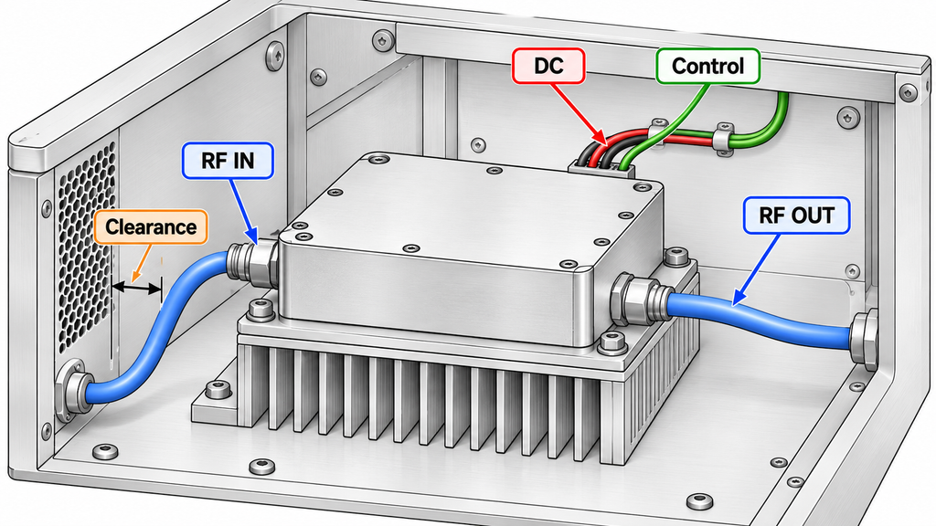
A revision can keep its rated RF performance while changing a connector, pin assignment or control state that the installed system depends on. Compare controlled drawings and interface definitions first, then test the affected behavior if the documents leave uncertainty.
Mechanical and RF connection. Check mounting-hole locations and tolerances, module height, baseplate geometry, heat-sink contact area, connector type and orientation, cable bend clearance and the space needed for installation. A module may physically enter the enclosure while changing how it seats against the cooling surface or how the coaxial cable mates. RF port labels are not substitutes for connector drawings.
DC and control. Verify connector pin assignments, polarity, permitted voltage and current conditions, grounding, and whether the installed wiring assembly remains suitable. Then compare logic voltage levels, enable or inhibit polarity, power-up timing, commands, acknowledgements where applicable, alarm meanings, fault states and recovery behavior. A controller that expects an active-high enable or a particular ready indication needs evidence that the replacement preserves that contract.
Document review may be sufficient for an explicitly unchanged, controlled interface when the customer’s approval rules allow it. A changed pin map, unknown logic level or unresolved mating definition requires the decision to stop before energizing or approving the replacement. Mechanical compatibility and controller compatibility must be recorded as separate findings.
Record which interfaces still meet the approved installation requirements and which need wiring, mounting, controller or validation changes. If those changes alter the approved system configuration, the revision is no longer an unconditional drop-in replacement for that project.
5. Can Thermal, Firmware, or BOM Changes Affect Drop-In Compatibility?
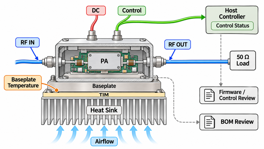
Some revision effects appear only after the module is mounted, warmed up or controlled through a complete operating sequence. They may be invisible in a short bench check at room temperature.
Thermal boundary. A revised baseplate finish, thermal-interface material, fastening requirement or internal heat path can change the relationship between the PA devices and the system heat sink. Compare the approved mounting and cooling conditions, the temperature measurement point and the duration required to represent the intended duty cycle. Review hot-state RF output, current and protection behavior where those paths may be affected. Matching cold-state power readings provide only cold-state evidence.
Firmware or control configuration. Some RF PA modules include firmware or configurable controllers; others use simpler fixed hardware logic. Where firmware applies, compare the approved and proposed versions, command interpretation, startup sequence, status timing, protection response and recovery rules. A firmware update that preserves the connector and pinout can still change what the host controller sees during a fault.
Critical materials and sources. A changed active device, matching-network component, temperature sensor, RF connector or thermal material may affect a different part of the approved operating envelope. Request a controlled impact assessment and evidence for the relevant RF, power, thermal or control path. A routine lot change from an already approved source belongs under its applicable lot controls; changes in component sourcing or second-source status need a separate assessment against the approved configuration.
If a critical component substitution or an applicable firmware or control-logic change cannot be assessed from the available documentation, suspend the drop-in compatibility conclusion and request the controlled change information.
Record which thermal, firmware and material changes are supported by documents, which need a targeted functional check and which remain unresolved.
6. When Is Targeted Revalidation Enough, and When Is Requalification Required?
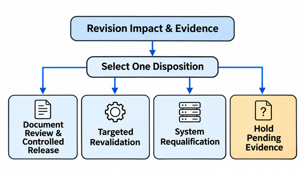
Choose the verification scope from the approved configuration, the change’s potential effects, the available evidence and the customer’s engineering or contractual approval rules. A supplier’s change classification does not determine whether the system needs requalification.
Assign one of four dispositions:
- Document review and controlled release. The revision difference is fully defined, no applicable approved boundary is affected, and the customer’s procedure permits acceptance on the available controlled evidence. Record that rationale and obtain the required approval.
- Targeted revalidation. The impact is limited to identifiable RF, mechanical, thermal, electrical or control conditions. Test or inspect those conditions against the original requirements, then restrict the decision to the evidence actually obtained.
- System-level requalification. A change affects an approved system interface, operating envelope or qualification basis, or the project’s approval rules require a wider assessment. Define the new scope through the responsible system authority rather than assuming that a successful module bench test closes the issue.
- Hold pending evidence. The original baseline, a critical revision change, a necessary interface definition or comparable test evidence is missing or contradictory. Obtain and assess it before approving the substitution.
For each proposed replacement revision, record one disposition, the evidence supporting it, any remaining restrictions, and the designated engineering or quality authority responsible for approval.
Hold may reflect missing supplier documentation rather than failed hardware. A passing targeted RF test supports its defined operating point; other frequencies, temperatures, waveforms or systems require corresponding evidence.
RF SKYPOWER can review the proposed module configuration, interfaces and evidence requirements with the OEM. The customer’s designated engineering or quality authority determines the verification scope and approves the substitution.
7. What Must Be Recorded Before Approving a Replacement Revision?
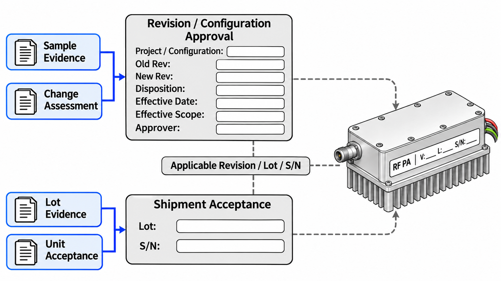
Purchasing needs to know which revision it may order. Receiving inspection needs to link that approval to the modules delivered.
The controlled replacement record should identify the old and new model/revision, the supplier change notice or engineering change number, and the affected project and operating conditions. Link the relevant drawings, interface definitions and verification reports by document revision. State the disposition (document review, targeted revalidation, requalification or hold), its justification, unresolved actions and the person or authority responsible for approval.
It also needs an effective date and scope: which assemblies or system configurations may use the revision, which purchase-order or procurement rules apply, and which production lots or serial-number ranges are included when applicable. Procurement, receiving and production records should carry that same approved revision identity rather than relying solely on a common marketing model name.
Keep four evidence levels distinct:
- Sample evidence describes the tested unit and stated test conditions.
- Configuration approval permits a defined revision under a defined project approval basis.
- Lot or batch evidence supports the production scope and sampling plan that were actually applied.
- Unit-level acceptance applies to the identified delivered serial number when the project requires individual evidence.
An approved sample does not establish the acceptance result of every future unit. When individual reports are required, their revision, conditions and serial-number linkage need to match the delivery. Revision-substitution approval and shipment acceptance remain separate decisions, each tied to its own evidence scope.
If the approver, effective scope or delivery traceability cannot be established, keep the replacement on hold. A verbal assurance that two versions are interchangeable is not a durable procurement instruction.
Conclusion
A revised RF power amplifier module is a justified drop-in replacement only when its changes have been evaluated against the original approved configuration, its RF and system interfaces still meet the applicable requirements, and the customer’s change-approval rules are satisfied. The same enclosure fit, model number or rated wattage alone cannot authorize the substitution.
Use the project’s controlled specifications, test plan and approval records to establish performance limits, acceptance thresholds and the authority to approve the substitution.
Before placing a replacement order, complete the eight-dimension impact matrix, resolve any non-comparable evidence and issue a revision decision tied to the applicable configuration and delivery scope.
For a project-specific RF power amplifier module replacement inquiry, send RF SKYPOWER the old and proposed model/revisions, change summary, intended system, frequency and waveform requirements, actual Pin and Pout definitions and reference planes, DC supply, cooling, RF and control interfaces, acceptance evidence requirements, and estimated quantity. These details allow a review of the proposed configuration and required evidence; drop-in approval remains a project decision.