










An RF signal generator can be damaged by unwanted RF energy returning through its output connector. Source-side protection must control that energy and keep exposure within the device’s allowable limits.
The design starts with three facts: the source’s permitted exposure, the downstream paths that can send energy back, and the RF level that reaches the source connector during actual operation.
Attenuators, isolators, limiters, and DC blocks address different hazards. Their ratings and placement determine whether they protect the source during normal transmission, RF switching, and fault conditions.
1. What Can Send Reverse RF Power Back Into a Signal Source?
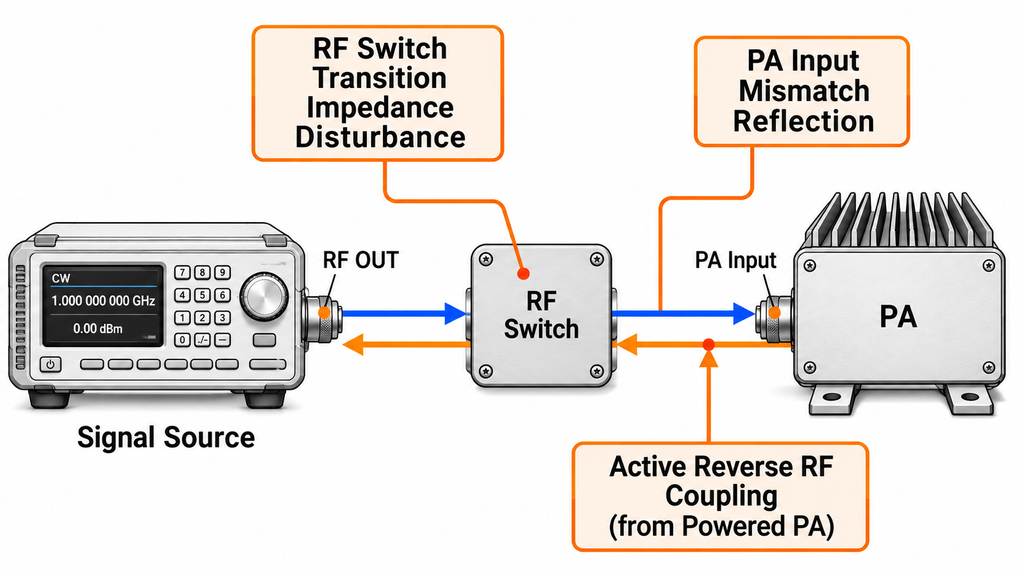
Reverse RF energy can reach a signal source through a mismatched PA input, active reverse coupling, or a changing RF switch path.
PA input mismatch is a common cause. The source drives the PA through cables and other RF components. When the PA input presents a poor match, part of the incident signal reflects toward the source.
The amount returning to RF OUT depends on the PA input reflection coefficient and the losses along the path. Input match may also change with frequency, bias condition, drive level, or temperature.
A powered PA introduces another possible source of reverse energy. Finite reverse isolation can allow unwanted RF signals to couple toward the PA input. An unstable amplifier may also generate signals that travel in that direction.
These active signals require their own assessment because they may differ in frequency, amplitude, and duration from reflections of the source waveform.
RF switches create exposure during state changes. While moving between paths, a switch may briefly present an unfavorable impedance. Open branches, poor terminations, and unsuitable switching conditions can increase the returned RF level.
The steady-state insertion loss of a switch reveals little about these transition events. Its switching behavior and permitted RF conditions matter.
DC exposure belongs in the same interface review. Bias networks or DC-carrying RF connections can place unwanted voltage on an RF path. RF attenuation and reverse isolation do not automatically provide DC protection.
A reflection at the PA output should be assessed separately. It reaches the signal-source connector only if the system provides a coupling path back through the amplifier and input chain.
Trace every credible return path from the PA input toward RF OUT. Include cables, switches, couplers, attenuators, bias connections, and terminations. Repeat the tracing for each relevant operating state.
2. Which RF OUT Limits Must Be Defined Before PA Connection?
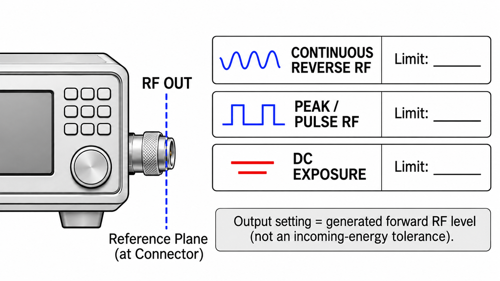
A source’s specified output power tells you what it can deliver during normal operation. It does not establish its tolerance to incoming RF energy.
Before approving source-side protection, obtain the applicable RF OUT exposure limits for the actual device model.
The engineering review needs:
- Allowable continuous reverse RF power at the source connector.
- Allowable peak or short-duration RF exposure, where specified.
- Pulse duration, repetition rate, and operating conditions attached to transient ratings.
- Permitted DC voltage or current exposure at RF OUT.
- Frequency, temperature, and source-state restrictions associated with those limits.
Use the source manufacturer’s technical documentation or a confirmed engineering response.
A model may publish its normal RF output level without stating a reverse-power survival rating. In that case, the output-level specification cannot serve as the missing limit.
The downstream conditions also need definition. Record the PA input match, possible reverse leakage, RF switch ratings, and the loads connected during each state.
Match the exposure measurement to the rating being evaluated. Compare sustained RF exposure with a continuous rating. For short events, use an instrument capable of resolving the relevant pulse and a corresponding peak or time-dependent limit.
If the source’s applicable limit is missing, record it as an open engineering requirement. The proposed protection arrangement can still be reviewed, but its source-port safety margin cannot yet be established.
3. Should You Use an Isolator, Attenuator, Limiter, or DC Block?
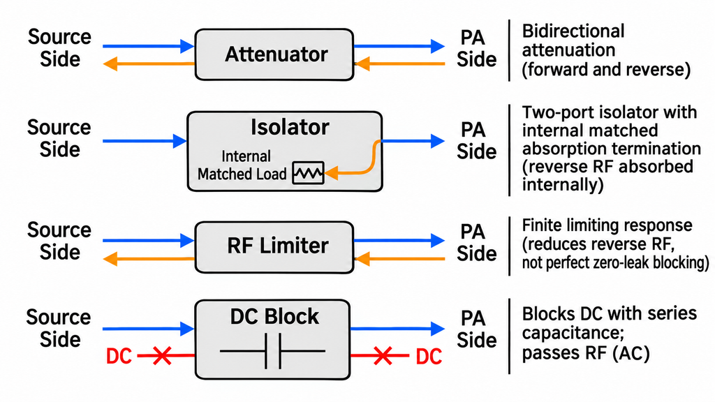
Choose the protection component according to the energy path and event it must handle.
A fixed attenuator reduces RF in both directions. An isolator passes forward RF with relatively low loss while directing reverse energy into a termination. A limiter restricts excessive RF levels within its specified response range. A DC block interrupts DC conduction.
Each option has different ratings and consequences for PA drive.
| Risk source | Possible energy path | Protection option | Rating to verify | System trade-off | Decision stop |
|---|---|---|---|---|---|
| PA input mismatch | Reflected source signal returns through the input chain | Fixed attenuator or isolator | Frequency range, return loss, power handling, insertion loss | Reduced PA drive or added component loss | Reflected RF OUT exposure cannot be bounded |
| Active PA reverse signal | RF energy couples from the powered PA toward its input | Isolator, attenuator, or suitable limiter | Reverse isolation, termination rating, peak exposure, operating band | Added loss, heat, or signal distortion | Return spectrum or energy exceeds verified ratings |
| RF switch transition | Changing switch impedance sends energy toward the source | RF blanking, rated switch, and upstream protection | Hot-switch or cold-switch rating, transition behavior, isolation | Added control timing or path loss | Actual switching conditions remain unverified |
| Excessive RF pulse | Short RF burst travels toward source RF OUT | Rated limiter with suitable passive protection | Threshold, response, leakage, recovery, pulse survival | Compression or waveform distortion | Event exceeds the limiter’s qualified response |
| DC on an RF connection | DC travels through a conductive RF path | DC block | Voltage rating, frequency range, RF power handling | Blocks intended DC feed and adds RF loss | Required DC continuity or voltage rating remains unresolved |
Consider a nominal 10 dB fixed attenuator between the source and PA.
For a reflection of the source’s own signal, RF passes through the attenuator on its way to the PA and passes through it again on the return path. With the same downstream match, the attenuator adds approximately 20 dB of round-trip attenuation.
An active reverse signal generated downstream makes only the return trip.
If +10 dBm enters the PA-facing port of a 10 dB attenuator, approximately 0 dBm reaches its source-facing port. This assumes 10 dB reverse-path loss and excludes other path effects.
The forward-drive calculation is different. A source delivering +8 dBm into that attenuator provides approximately −2 dBm at the PA-facing port, before other losses.
These calculations show how the path behaves. They are not acceptance values for either RF SKYPOWER SDR model.
For an isolator, check its transmission direction, isolation over the frequencies of concern, and termination power rating. The termination must absorb the reverse energy expected during the relevant events. A PA-output isolator or circulator routes load reflections away from the amplifier output. The source-side isolator discussed here handles RF returning through the PA input chain.
For a limiter, examine its threshold, leakage during limiting, response time, recovery, and pulse survival. A limiter that reacts too slowly may allow the event of interest to reach the source.
A DC block requires its own voltage and RF power checks. It also changes any interface that intentionally carries DC through the coaxial connection.
4. Where Should Source-Side Protection Components Be Installed?
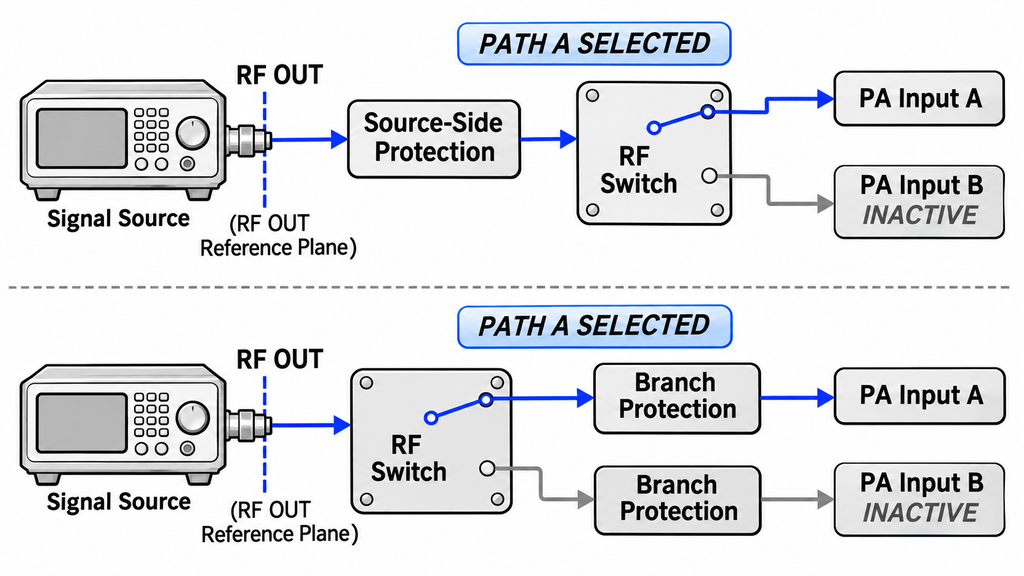
Install source-side protection upstream of the return paths it is intended to control.
For a signal generator feeding a switched PA input, one arrangement is:
Signal Source → Source-Side Protection → RF Switch → PA Input
Here, the protective component sits between RF OUT and the switching network.
Another arrangement places protection within individual PA branches:
Signal Source → RF Switch → Branch Protection → PA Input
Branch protection can address energy returning from a selected PA input. The source, however, still sees the upstream switch and its transition behavior.
The difference is the location of the protected boundary. An attenuator or isolator affects the RF paths that pass through it; its position determines which return events it can reduce.
Keep the first protective component close to RF OUT where practical. Extra cable length and connectors between the source and protection add potential mismatch points.
Use the RF OUT connector as the source-side reference plane during qualification.
If a directional coupler measures reverse RF downstream of an isolator, its reading represents the RF condition at that measurement location. Calculate or measure the effect of every intervening component before reporting exposure at RF OUT.
The forward path needs equal attention. Account for insertion loss when calculating PA input drive. Any increase in source output to compensate for protection losses must stay within the source’s approved operating range.
The final arrangement should deliver the required PA drive while keeping source-port exposure within its applicable limits.
5. How Should RF Blanking and Switch Interlocks Be Sequenced?
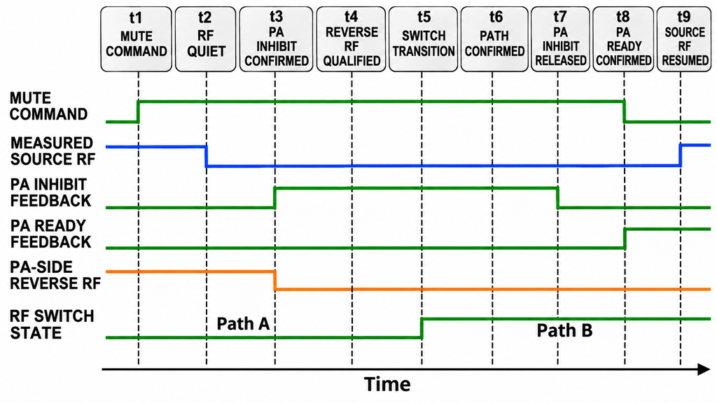
The SDR-to-PA power-on sequence establishes when RF drive is permitted under the PA manufacturer’s bias and enable requirements. A switch interlock must also define when that drive is withdrawn before the RF path changes.
Before switching, verify that RF OUT is quiet, PA inhibit feedback is valid, and PA-side reverse RF is below the qualified transition threshold. A mute-command acknowledgement alone does not establish these conditions.
| System state | Source RF state | PA ready/enable condition | Switch and load state | Permitted next action | Required observation | Validation criterion/evidence |
|---|---|---|---|---|---|---|
| Safe idle | Muted | PA inhibited; applicable bias prerequisites known | Defined termination or qualified path | Configure source and select path | RF level and switch-state record | No unintended RF at the defined observation points |
| Frequency or waveform setup | Muted | PA inhibited | Selected path held stable | Apply frequency, gain, or waveform settings | Command log and time-aligned RF trace | Configuration completes without an unqualified RF event |
| Mute request | Stop or mute command issued | PA inhibit condition maintained | Existing path unchanged | Wait for confirmed RF quiet | Measured RF envelope at relevant points | Qualified quiet interval established before switching |
| RF switch transition | Confirmed RF quiet at source RF OUT | PA inhibit feedback confirmed; PA-side reverse RF below the qualified transition threshold | Switch moves toward a rated load path | Wait for switch feedback and settling | Source-side RF, PA-side reverse RF, PA inhibit feedback, and switch state | No exposure-limit crossing; destination path confirmed |
| PA preparation | Muted | PA bias and ready sequence follows model requirements | Selected path and load confirmed | Authorize transmission when prerequisites are met | PA-ready indication and RF observations | PA readiness confirmed before RF drive |
| Normal transmission | Active within approved drive budget | PA enabled under qualified load | Path remains fixed | Monitor operation | Forward RF, reverse RF, and PA status | All applicable exposure and operating limits maintained |
| Fault or shutdown | RF may be active at fault onset; actual mute response recorded | PA inhibit or shutdown requested; actual response recorded | Path held or routed as permitted by the fault-handling design | Latch fault; restore operation only after safe-state verification | Initial RF peak, mute latency, PA inhibit timing, and final switch state | Exposure assessed against applicable limits; no uncontrolled restart |
For planned switching, measure how long the source takes to reach the qualified quiet level. Include the response of the PA inhibit control and the settling time of the switch.
An unexpected fault follows a different timeline. RF may still be active when the fault occurs. Capture its initial level, the largest transient, the actual mute response, and the PA shutdown timing.
The selected RF switch may impose separate hot-switch and cold-switch limits. Apply those limits to the measured sequence.
6. How Can Reverse Power and Switching Transients Be Measured?
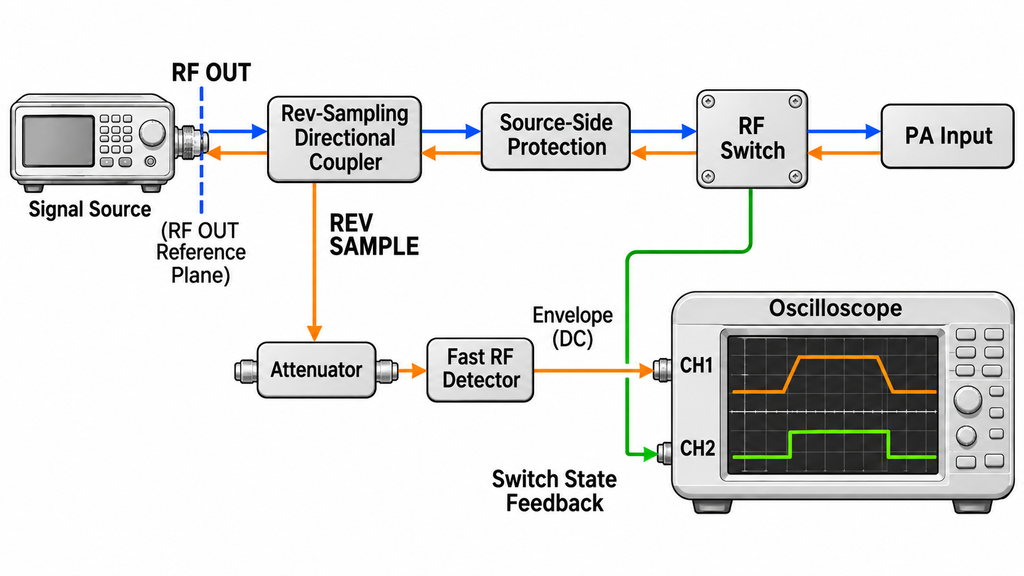
Measure reverse RF at a defined reference plane, preferably the RF signal generator’s RF OUT connector.
A directional coupler can sample energy traveling toward that connector. Orient the coupler for the intended direction and connect its sample port to a suitable RF receiver, power sensor, or time-domain instrument.
Correct the reading for the coupling factor and sample-path loss. If the coupler is away from RF OUT, also account for the RF path between the coupler and the source connector.
Finite coupler directivity can affect a small reverse-power measurement.
When forward RF is much stronger than the returning signal, leakage into the reverse sample port may create an apparent reverse-power indication.
Check coupler directivity, port matching, and the measurement floor. Establish a baseline using an appropriate qualified termination. If the indicated reverse RF falls near the system’s leakage or noise limit, obtain a measurement with adequate discrimination before treating it as a confirmed event.
Switching transients require sufficient time resolution.
An average-power measurement may conceal a short spike. A peak detector can also understate the peak if its response is too slow. Choose measurement bandwidth, detector response, and triggering for the expected event duration.
Keep the following information with each measurement:
- Peak or average RF level, according to the applicable limit.
- Event duration and timing relative to switch control.
- Source state, PA state, and selected RF path.
- Coupling-factor and path-loss corrections.
- Measurement uncertainty and detection limits.
Measure DC exposure separately. A directional RF coupler does not establish the voltage present at a connector or bias network. Use a voltage measurement method rated for the expected electrical conditions.
Align the RF trace with the control log. The record should show whether an event followed a mute command, PA state change, switch movement, or unexpected fault.
7. How Do You Validate Protection Under Real Switching States?
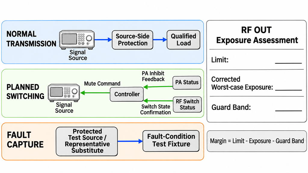
Qualification should reproduce the operating states that could expose RF OUT to unwanted energy.
Begin with a protected RF path and a qualified load. Measure normal source drive, forward-path loss, and reverse RF at the source reference plane.
During normal transmission, record representative frequencies, source settings, PA operating conditions, and protection-component losses.
Next, test the transitions. Include muting, frequency or waveform changes, RF switch movement, PA enable, and shutdown. Capture both the control sequence and any short RF events.
Fault testing should cover credible abnormal conditions, such as an unavailable branch, incorrect termination, or missing switch confirmation.
Characterize hazardous paths with suitable protected fixtures or representative substitutes before exposing the actual source hardware. The test setup should prevent an uncontrolled event from damaging the equipment being evaluated.
For each relevant event class, identify the worst measured exposure at RF OUT.
Where the source has a documented RF power limit in dBm, calculate the margin as follows:
Margin (dB) = Applicable Reverse-Power Limit (dBm) − Corrected Worst-Case Exposure (dBm) − Measurement Guard Band (dB)
Use three distinct inputs:
- Applicable reverse-power limit: The source manufacturer’s limit for the relevant frequency, operating state, and exposure type.
- Corrected worst-case exposure: The largest measured value after coupling and reference-plane corrections, before applying the uncertainty guard band.
- Measurement guard band: The allowance assigned to measurement uncertainty. If the corrected exposure already includes that allowance, do not subtract it again.
A positive margin shows that the measured exposure, including its guard band, is below the applicable RF power limit.
This calculation addresses the RF exposure represented by that limit. DC voltage, switching behavior, and other possible damage mechanisms require their corresponding checks.
Compare like quantities. A continuous reverse-power rating does not automatically qualify a short pulse. Match peak or time-dependent exposure to a suitable manufacturer limit.
The test record should also show that planned switching occurred under the approved source and PA conditions. For fault events, document the actual transient and shutdown response.
When a device limit or measurement is unresolved, identify the missing rating or measurement capability. That evidence determines whether the protection can be accepted.
8. What Should Be Verified for Single- and Dual-Output SDR Sources?
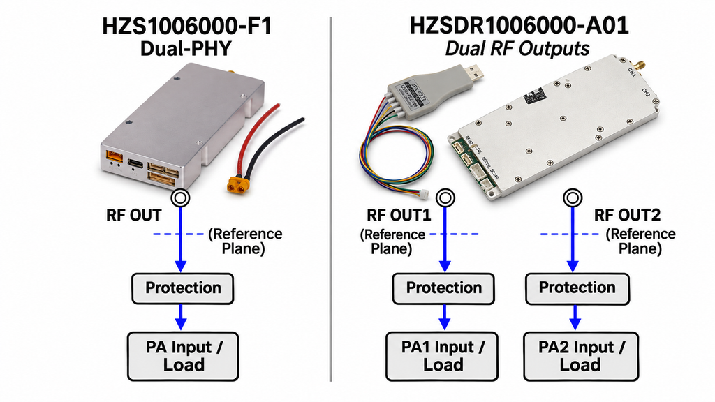
The RF SKYPOWER SDR signal-source modules include two different output architectures. The HZS1006000-F1 uses Dual-PHY with one physical RF OUT, while the HZSDR1006000-A01 provides two independent physical RF outputs.
For the F1, source-side protection applies to its single external RF connector. Its documentation includes AT+STOPLOAD for stopping transmission. Measure the actual RF response at that connector before using the command in a switching interlock.
For the A01, each RF output needs a defined protection path, an applicable exposure limit, and a measurement reference plane.
Check three operating cases:
- RF OUT1 transmits while RF OUT2 is muted.
- RF OUT2 transmits while RF OUT1 is muted.
- Both outputs transmit, including a frequency or waveform change on one channel while the other remains active.
The third case checks how the channels behave under shared control and power conditions. Separate RF connectors establish the physical output count, while measured behavior determines the switching requirements.
Record the protection components, PA connection, reference plane, and actual RF state for each output.
The F1 and A01 therefore require different source-side protection diagrams and test coverage. Final acceptance should use the confirmed reverse-power and timing limits for the selected model.
| SDR Signal Source | RF Output Architecture | Source-Side Protection Focus | Documentation |
|---|---|---|---|
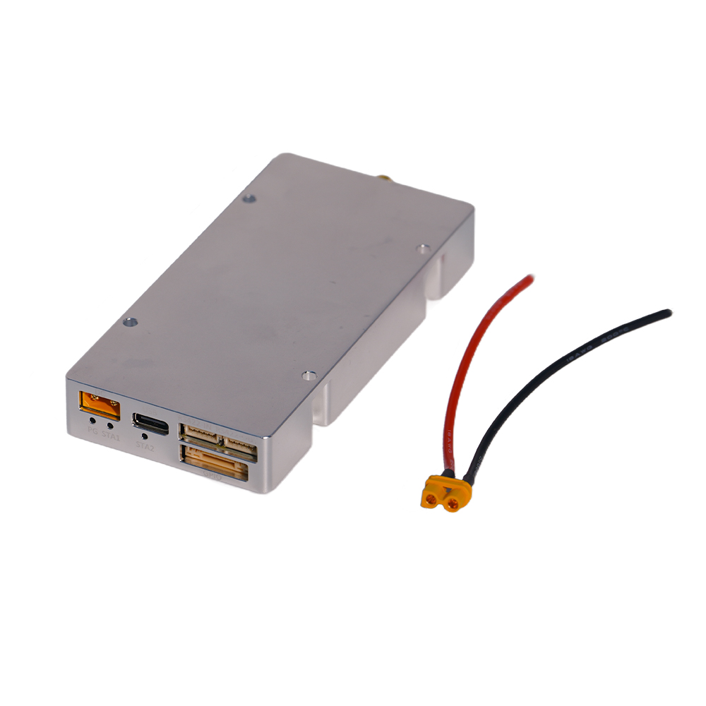 HZS1006000-F1Real product photo | Dual-PHY architecture with one physical RF OUT port | Measure reverse RF power at the single RF OUT port. Verify the actual RF output response after issuing AT+STOPLOAD. | F1 Instruction Manual (PDF) ↗ |
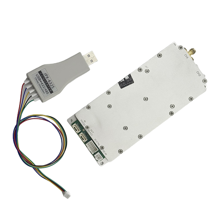 HZSDR1006000-A01Real product photo | Two independent physical RF outputs (RF OUT1 and RF OUT2) | Assess reverse RF exposure at each output separately. Verify single-output and simultaneous dual-output operating states. | A01 Instruction Manual (PDF) ↗ |
Swipe horizontally to compare both RF output architectures →
Conclusion
Protect an RF signal generator by identifying credible reverse-energy paths, placing appropriately rated protection between those paths and RF OUT, and measuring exposure during transmission, switching, and faults.
This approach can establish whether a proposed protection path and control sequence keep measured RF exposure within a documented source limit. The actual model’s survival ratings, qualified switching thresholds, and acceptance values still require manufacturer evidence and appropriate testing. Protection at the PA output and acknowledgement of a mute command do not establish source-port safety on their own.
Before approving the interface, draw the complete source-to-PA RF path. Mark every physical RF output, switch state, termination, and possible return path. Match each credible exposure to an applicable limit and measurement method.
For an RF SKYPOWER engineering RFQ, provide the SDR source model, operating frequencies, PA input conditions, RF switch topology, proposed protection components, and available RF measurements. RF SKYPOWER can use these details to review the source-to-PA interface and identify the evidence required for the project.