










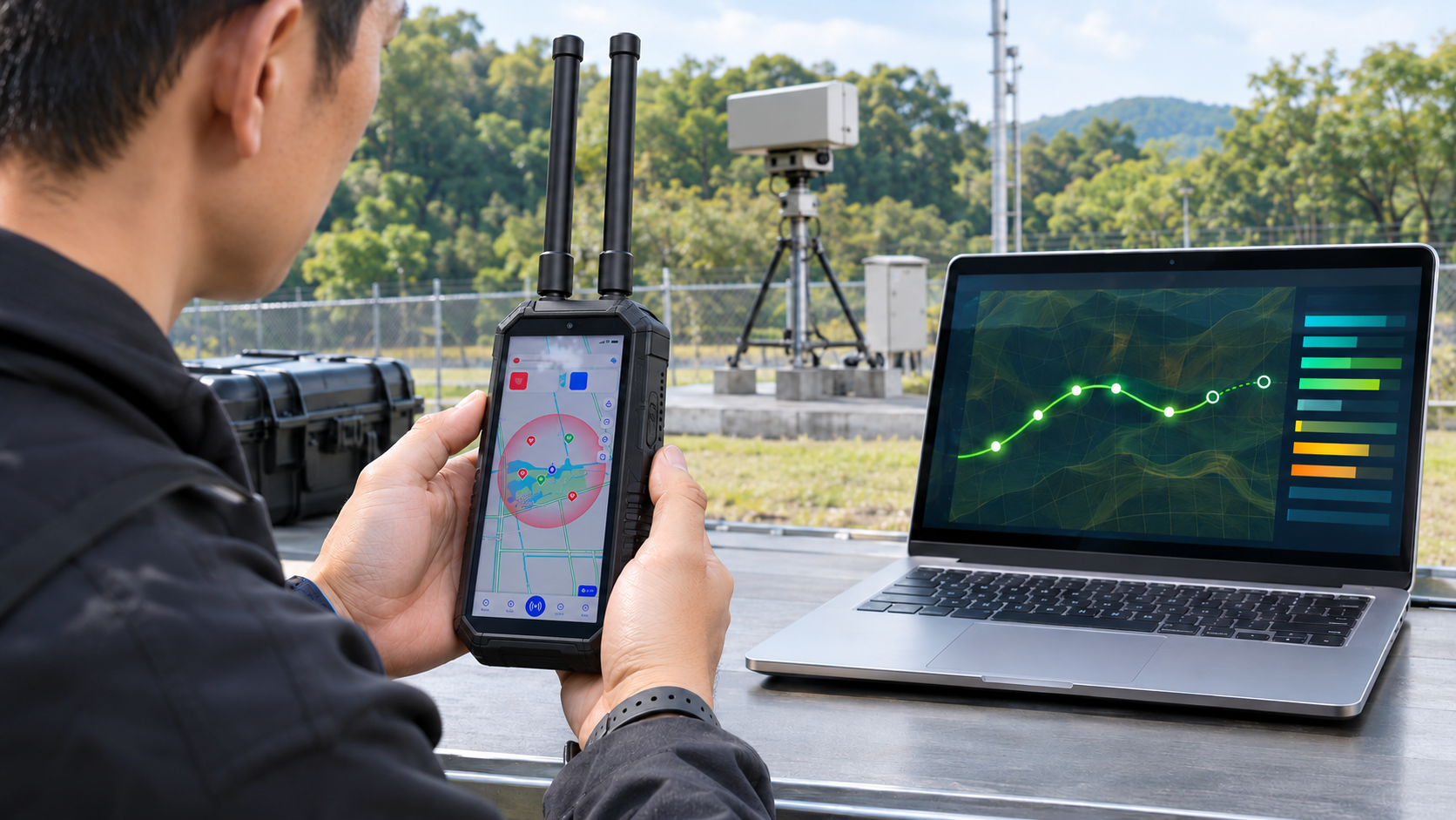
A drone tracking system and an RF detector may both produce time-stamped records. An RF alert, a coordinate reported in a radio message, and a maintained track describe different outputs. Compare their records only after aligning the event, source, target association, time, and reference conditions.
1. What Is the Difference Between an RF Alert and a Drone Track?
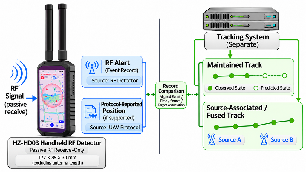
An RF alert marks a detected event. A track links position or motion information over time. Device labels alone do not tell a buyer which result is available.
Four output types appear in procurement documents:
- RF detection alert: A receiver registers RF activity that meets its detection criteria. The event may include time and signal details, but it does not establish physical target coordinates.
- Decoded identity or reported position: A supported protocol may carry a drone identifier or a position reported by the transmitting source. A sequence of decoded positions can produce a moving map display.
- Maintained target track: A tracker associates successive position or motion records. Its inputs may be target reports, measurements from one sensor, or both. The track state distinguishes new input from prediction or holding.
- Associated or fused track: Some systems combine observations from different sources. This is a maintained track with extra association and handoff records where supported.
An RF receiver may hear an aircraft downlink, a controller uplink, or an identification broadcast. Dedicated RF direction-finding systems can estimate an emitter’s bearing. Multi-receiver RF geolocation systems can estimate an emitter’s position using suitable timing or angle measurements, calibrated sensors, and known receiver geometry. These emitter measurements need different source labels from coordinates decoded out of a drone message.
An RF warning and a moving map path can look equally active. Their records should show whether the position is reported, measured, held, or predicted.
Pair an HZ-HD03 screen recording with its corresponding event record, where available. The two records show which fields update live and which appear in the event history.
Handheld patrols often prioritize timely alerts, while fixed sites may need mapped positions or sustained tracks—an important distinction when choosing a drone detector.
2. Which Tracking and RF Detector Outputs Are Directly Comparable?
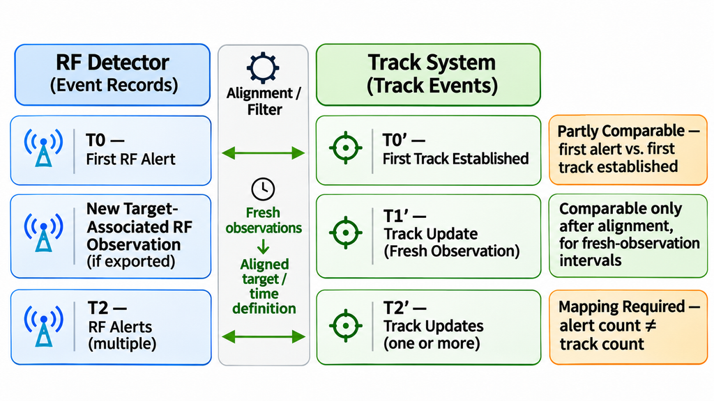
Directly comparable means both records describe the same defined metric under aligned conditions. Partly comparable means the outputs share a measurable quantity but support different conclusions. Not yet comparable means an essential mapping or definition is missing. Providing that mapping may permit an association check without making the original fields equivalent.
| The two outputs compared | Comparability | Conditions to align | What the comparison can support | What it cannot support |
|---|---|---|---|---|
| First RF alert vs first track established | Partly comparable | Same test flight; documented RF-event-to-aircraft association and link origin when known; shared reference start, synchronized clocks, and defined milestones | Relative timing of the two milestones | Equal detection latency or proof that an RF emitter is the aircraft |
| Protocol-reported position vs sensor-measured position | Partly comparable | Target association, observation time, coordinate datum, altitude basis, and units | Spatial agreement between the reported and measured positions | Independent accuracy or ground truth based on agreement alone |
| Decoded protocol identity vs internal track ID | Not yet comparable | Time-stamped identity-to-track mapping and association rules | Whether an identity was linked to a track | Direct equality of two different ID types or proof that the association is correct |
| New-observation intervals from two event streams | Directly comparable after alignment | Both systems expose fresh-observation events; align their definitions, clocks, windows, and target association | Cadence and gaps in new target observations | Position accuracy or a track-update comparison when one device exports alerts only |
| RF alert count vs maintained track count | Not yet comparable | Alert grouping, duplicate handling, target association, and count definitions | How alerts map to established tracks once the rules are known | A like-for-like target count from raw alert totals |
| Completeness of two event or track logs | Directly comparable after alignment | Common required fields and aligned window; document counter resets and filtering where sequence IDs exist; use independent reference events to assess missed detections | Missing fields, unexplained sequence gaps where counters are reliable, and differences against the reference event list | Proof that all real target events were detected from log completeness alone |
Swipe horizontally to compare all output conditions and limits →
One transmitting target may generate multiple RF alerts while a tracking system keeps one track open. Ask for the alert-grouping and target-association rules before comparing counts.
3. What Do Update Rate, Latency, and Track Age Actually Mean?
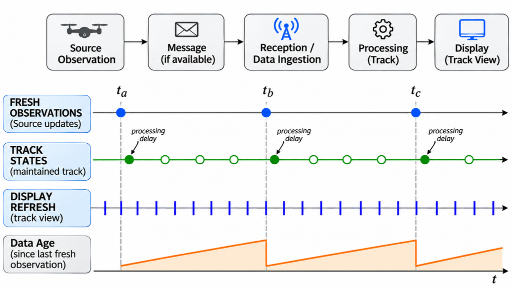
A drone tracking system may publish a new track state using fresh observations or a predicted position. Buyers should separate new-observation rate, track-state output rate, and display refresh rate. Only the first shows how often fresh target observations arrive.
To compare timing, identify these points in the data path:
- Observation time: When the underlying position was measured or estimated by its source.
- Message time, if available: When the source created or transmitted the message carrying that position. A reported position can predate its transmission.
- Reception time: When the monitoring system accepted the observation or message.
- Processing time: When the system classified the event or updated the track state.
- Display time: When the interface presented that state to the operator.
For cross-device latency, require synchronized clocks and named timestamp events. When an export lacks a timestamp, the corresponding delay remains unmeasured.
New-observation interval measures the gap between successive valid observations for the same target. Track-state output interval measures how often the processor publishes a state, including predicted states where applicable. Latency measures the delay between defined time points. Data age describes how long it has been since the last valid source observation.
Track age normally runs from the track’s first occurrence. That differs from the data age defined above. Ask for the supplier’s field definitions when its interface uses different labels.
After one valid position, a track processor may publish several predicted points. Each state has its own processing time, while the last observation time stays fixed. Data age rises until the next observation.
Ask for the longest gap between fresh observations, the defined latency endpoints, and a sample that marks held or predicted states. Set acceptable values from the project’s operating needs, not the interface frame rate.
4. Are Position, Altitude, and Heading Measured on the Same Basis?
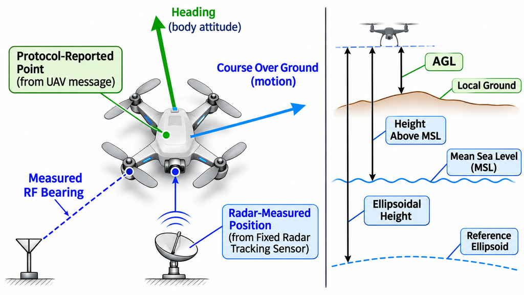
Two latitude-and-longitude pairs may look identical in format but use different sources, references, or times. A target-reported coordinate can be compared with a sensor measurement after alignment. Their agreement does not make the sources independent evidence of accuracy.
Check the reference for each field before calculating a difference:
- Horizontal position: Geographic coordinates or local coordinates, the stated datum, and any local origin or conversion.
- Altitude: Height above local ground, height above mean sea level, or height above a reference ellipsoid. These are distinct vertical references.
- Position dimensions: A two-dimensional point may omit altitude; a three-dimensional point needs a defined vertical component.
- Speed: Ground speed describes motion over the ground. Radial speed describes the component of motion toward or away from a sensor.
- Direction: Vehicle heading describes where the body points. Course over ground follows the direction of motion. Sensor bearing is another quantity. State whether an angular reference is true or magnetic north where relevant.
Compare positions at matched observation times. Differently timed points can create an apparent spatial error even when their coordinate references match.
A coordinate decoded from a drone telemetry or identification transmission is a source-reported position. Record the message type and timestamp before comparing it with a sensor measurement.
Specify the coordinate system, horizontal and vertical references, units, conversion rules, and applicable position times. If a key basis is missing, hold the corresponding error comparison until the supplier defines it.
5. Can Confidence Scores and Tracking Accuracy Be Compared?
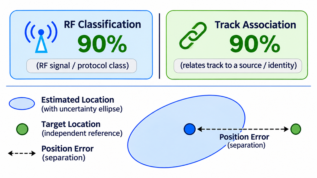
A confidence score needs a defined subject. A percentage beside an RF classification and one beside a tracked position may come from unrelated calculations.
Keep four measures separate:
- Detection or classification confidence concerns whether an event or signal matches a defined class.
- Identity evidence concerns the identifier or model information obtained from a supported source, including its provenance.
- Track association confidence concerns whether observations belong to the same tracked target.
- Position uncertainty and error describe different quantities. Uncertainty estimates the spread of a position result under a stated statistical definition. Error is the difference from a time-matched independent position reference.
For classification scores, request the meaning, calibration or verification method, and validation scope. For location error, request the error metric and time-matched independent reference. An uncertainty radius needs a unit and stated statistical coverage.
One display might show “90%” for RF classification, while another uses it for target association. Compare those scores only after checking what each percentage measures. Evaluate position error against a separate, time-matched reference.
6. What Happens When a Track Is Lost, Reacquired, or Handed Off?
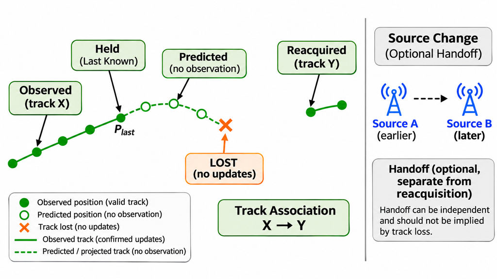
Track continuity depends on how the system handles observation gaps, target association, and state changes. A complete path on screen can contain both observed and estimated segments.
A useful state sequence distinguishes:
- New observation: The system receives fresh target data and updates the relevant track.
- Temporary observation gap: No fresh data arrives, although the system may still retain the track.
- Predicted or held state: The display continues with an estimated or last-known position, labeled as such.
- Track lost: The system closes or marks the track lost under its defined rule.
- Reacquired: Following a declared loss, the system associates a new observation with the earlier target under a defined rule. It may instead open a new track.
- Source handoff, if supported: A tracking system changes or adds a contributing sensor while preserving a record of the sources and association decision.
A target may resume updates during a temporary gap. After formal loss, the next association must be recorded as reacquisition or a new track under the system’s rules.
An unchanged track ID may span a predicted interval. A changed ID may refer to the same physical target after reacquisition. With several targets in view, IDs can also swap. Evaluating such mistakes requires independent, target-matched evidence.
Require the gap and loss thresholds, state labels, old-to-new ID mappings, and the source of each valid observation. For sensor handoff, request the contributing sources and the handoff event. Compare continuity within a common window and under aligned state definitions.
7. Which Raw Records Support a Track Continuity Audit?
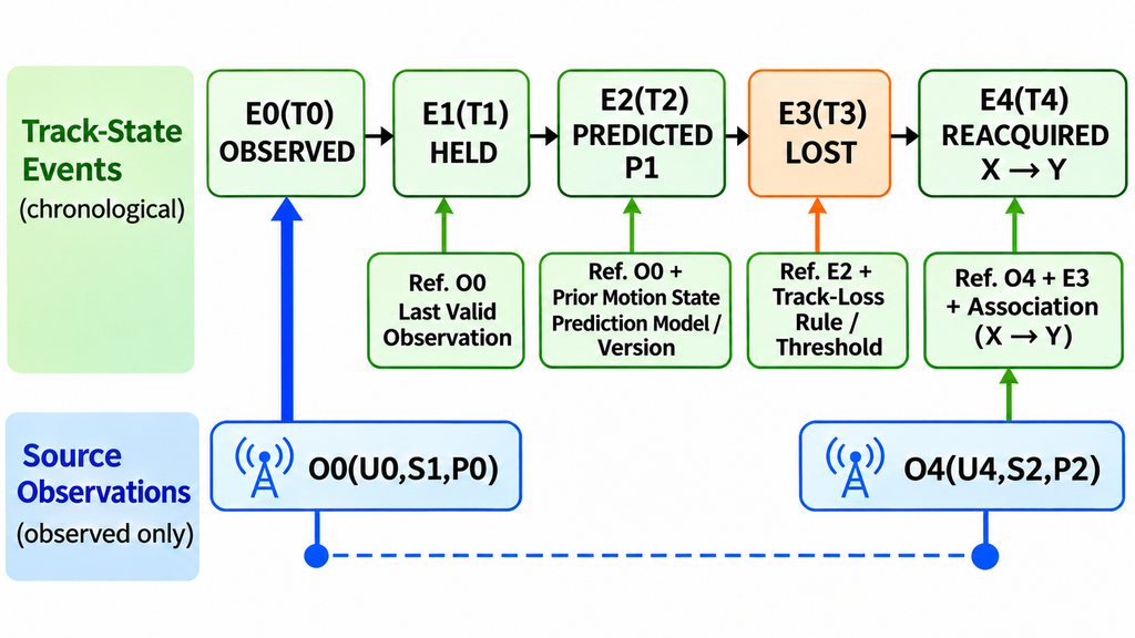
A track display shows the result of processing. Its source and continuity are checked through two linked record types: source-observation records for incoming messages or measurements, and track-state events for holding, prediction, loss, and association decisions.
The table below is a proposed export structure. T0–T4 are track-state event times; U0 and U4 mark the source-observation times for O0 and O4. All times use a common clock. P0 and P2 are observed positions, while P1 is predicted.
| State event time / source observation time | Target / track association ID | Sensor or data source | Coordinates / basis | Observation / track state | Valid update interval / data age | Confidence / uncertainty, if supported | Loss / reacquisition | Handoff, if supported | Source and state record references |
|---|---|---|---|---|---|---|---|---|---|
T0 / U0 | Target A; track X | Observation S1 | Observed P0; datum D; height basis H | Observed | Age = T0 − U0; earlier interval outside sample | Source uncertainty or association score, if exposed | Active | None | Observation O0; state E0 |
T1 / last U0 | Target A; track X | Track processor; last source S1 | Last observed P0; D/H | Held; no new observation | Age = T1 − U0 | Held-state uncertainty or last valid score with age | Gap open | None | State E1 → observation O0 |
T2 / last U0 | Target A; track X | Track processor; last source S1 | Predicted P1; D/H | Predicted | Age = T2 − U0 | Predicted-state uncertainty and its definition, if exposed | Gap open | None | State E2 → prior motion-state record (position, velocity or other motion estimate, and state time) → observation O0; prediction model/configuration version |
T3 / last U0 | Target A; track X | Track processor; last source S1 | Last valid or predicted point, marked | Lost | Age = T3 − U0 | Last score or uncertainty marked stale or unavailable | Loss event and rule | None | State E3 → prior state E2; loss-rule reference |
T4 / U4 | Target A; previous X → current Y | New observation S2; association processor | Observed P2; D/H | Reacquired under stated rule | Age = T4 − U4; observation gap = U4 − U0 | New observation uncertainty and X → Y association score, if exposed | Link X → Y recorded | Source change logged; handoff separate | Observation O4; state E4 → E3; X → Y association decision/rule reference |
Swipe horizontally to follow the complete observation-to-reacquisition record →
At T1–T3, the track states still depend on O0, so data age rises from U0. At T4, the new observation O4 gives a current data age of T4 − U4, while U4 − U0 gives the gap between observations. The recorded X → Y association documents reacquisition; uninterrupted sensor handoff requires a separate record.
Request the field dictionary, machine-readable export, and stable record IDs for the test window. Prediction and association entries should identify their input states and rule versions. Use these records to audit the internal event chain, then compare claimed target continuity with a time-matched independent reference.
What Should Buyers Specify in a Tracking Output RFQ?
State the required output level in the RFQ. A supplier can then answer with a field dictionary and sample records, rather than a generic “tracking” claim.
- Level 1 — Alerts and identification. Specify target models and protocols, alert triggers, supported identity fields, first-event time, grouping rules, and event records. This level supports mobile tasks centered on RF signal awareness and supported-target recognition.
- Level 2 — Position and motion. Require reported-versus-measured source labels, position epoch, coordinate and altitude references, speed and direction definitions, and uncertainty fields where available. Ask for the associated source message or measurement reference.
- Level 3 — Continuous tracks and handoff. Specify track IDs, fresh-observation and state-output timing, prediction flags, loss and reacquisition rules, target association, and source handoff if supported. Require chronological observations and track-state events.
Across these levels, define the deployment type, operating conditions, target/protocol scope, simultaneous target count, time window, export rights, and demonstration evidence. Set numerical limits for latency, gap duration, and error from the project requirement and its test method.
For patrols and temporary security tasks centered on passive RF reception, review the HZ-HD03 Handheld RF Drone Detector. It uses passive RF/SDR reception and does not actively transmit RF detection signals during detection. Confirm supported targets, identification fields, and event records for the current software version. If coordinates are required, request the source and meaning of each displayed field.
Fixed monitoring projects that need independently measured positions or sustained multi-target tracks should define those outputs at the system-architecture level. Sensor handoff adds a separate association and source-record requirement.
Compare an RF detector and a drone tracking system by event, target, clock, and reference basis. A moving map may contain held or predicted points. Request a field dictionary and time-ordered sample to establish when fresh observations arrived. Site-specific tracking accuracy, latency compliance, and acceptance still require independent reference tests. For an RF detection and tracking project, send RF SKYPOWER the required alert, identity, timestamp, and export fields for engineering review.