










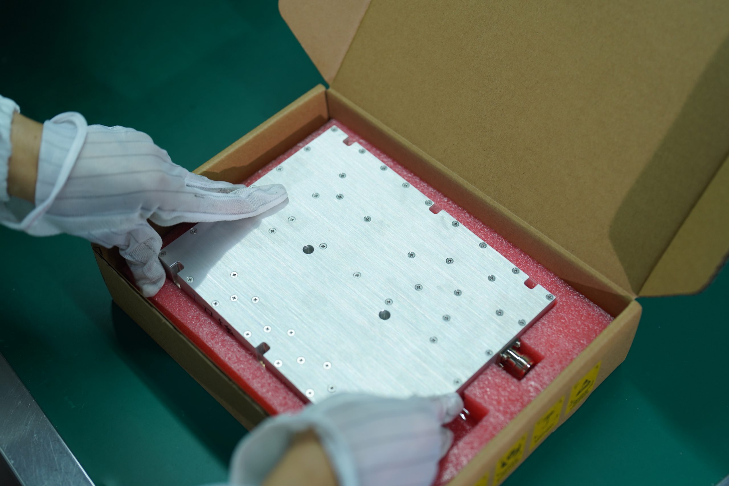
Automated RF PA testing becomes critical when an approved sample moves into batch production. A carefully tuned golden sample proves that one RF PA can meet the target under its approved hardware state and test conditions. It does not prove that later production units will remain inside the same acceptance window.
Automation does not create manufacturing consistency. It protects consistency by applying one controlled test recipe, exposing unit-to-unit variation, identifying process or test-station drift, and preserving comparable production records.
RF Power Amplifier Modules should not move from sample approval to batch delivery until the product baseline, measurement boundaries, test recipe, acceptance limits, and unit-level reporting method are defined.
The real production question is not whether an experienced engineer can make one module pass. It is whether later modules can be evaluated under the same controlled rules without depending on one person’s memory or judgment.
1. Why a Tuned Golden Sample Does Not Guarantee Production Consistency
A tuned golden sample proves that the design can meet its target. Production control must prove that later units can remain inside the same acceptance window without depending on one engineer’s memory or personal judgment.

During development, an RF engineer may adjust:
- bias or static current;
- matching components;
- input-drive conditions;
- harmonic-suppression elements;
- protection thresholds.
These adjustments may be necessary during prototype development. Once the design is approved, the accepted configuration must become a controlled production baseline.
Later units may still vary because of component tolerances, assembly differences, thermal-interface coverage, mounting torque, grounding, shielding contact, connector installation, or test-fixture condition.
This creates an important distinction.
A golden sample demonstrates:
This unit can meet the target under the approved adjustment and test condition.
Batch production must demonstrate:
Later units can be evaluated under controlled rules and remain within the approved acceptance window.
Production modules do not need to produce numerically identical results. Normal component and assembly variation will remain.
The requirement is that each module:
- stays inside defined limits;
- is evaluated through the applicable approved recipe;
- preserves its actual measurement results;
- receives a traceable release decision.
Controlled Adjustment Is Not the Same as Uncontrolled Retuning
Some RF PA production processes may allow limited unit-level adjustment, such as:
- static-current setting;
- bias adjustment;
- approved matching-part selection;
- controlled calibration-value programming;
- engineering-authorized rework.
These activities do not automatically indicate poor consistency.
They become controlled production work only when the following are defined:
- which parameters may be adjusted;
- the permitted adjustment range;
- who is authorized to make the adjustment;
- which before-and-after values must be recorded;
- which tests must be repeated afterward.
The problem is not adjustment itself. The problem is unrecorded adjustment based on personal judgment, followed by a report that shows only the final PASS result.
A tuned golden sample proves that the design can pass; production control proves that later units can pass without uncontrolled retuning.
2. What Must Be Controlled Before Automated Production Testing Begins
Automation can repeat only what has already been converted into a controlled production rule.
Running the same software does not create comparable evidence if the hardware configuration, fixture, corrections, input method, or limits change without review.

The production baseline should define:
- product model and controlled configuration revision;
- approved BOM and matching-component state;
- bias or static-current limits;
- firmware or control version;
- approved test frequencies;
- fixed-Pin or target-Pout input method;
- load and cooling conditions;
- input and output reference planes;
- test fixture and RF-path corrections;
- acceptance limits;
- test software and recipe versions.
For a 300–1200 MHz RF Power Amplifier Module, each production unit should follow the frequency map approved for its controlled configuration and recipe revision. Frequency points should not be changed informally to make a weak result easier to pass.
Controlled Does Not Mean Permanently Unchangeable
Fixtures, correction files, software, recipes, and hardware revisions may need to change.
A change becomes controlled when it is:
- reviewed;
- approved;
- versioned;
- validated;
- linked to the affected S/N range.
Without this control, two reports for the same model may no longer be directly comparable.
A Golden Sample Is Not a Calibration Standard
A golden-sample approval record documents the accepted product configuration and its demonstrated performance. It does not automatically calibrate the test instruments or RF path.
The sample itself may change because of repeated full-power operation, thermal cycling, connector wear, repeated installation, bias drift, or aging.
The roles should remain distinct:
| Controlled item | What it establishes |
|---|---|
| Golden-sample approval record | The approved design and configuration can meet the target |
| Traceable calibration standard | The instrument or measurement path is calibrated |
| Controlled reference unit | The test station has not developed an obvious shift |
| Production-unit test | The delivered S/N meets the approved limits |
A controlled reference unit can help detect an obvious station shift. It does not replace traceable instrument calibration, RF-path verification, or correction-file control.
Multiple Test Stations Must Produce Comparable Results
If more than one production station is used, station-to-station correlation should be established before their results are treated as interchangeable.
Two stations may run the same recipe but still differ because of:
- power sensors;
- spectrum analyzers;
- directional couplers;
- test cables;
- fixtures;
- loads;
- DC supplies;
- warm-up or environmental conditions.
Station control should identify:
- station ID;
- applicable fixture and recipe versions;
- correlation date;
- permitted inter-station difference;
- correlation status.
The same software recipe cannot protect batch consistency if different stations introduce uncontrolled measurement offsets.
Automation protects consistency only after the product state, measurement boundary, station relationship, recipe, and release rules are controlled.
3. How Automated Frequency-Point Testing Reduces Operator Variation
Manual testing requires an operator to repeat the same actions at every frequency: set the source, wait for the measurement, check the spectrum, record the result, and move to the next point.
Each repeated action creates an opportunity for variation.
Typical risks include:
- skipped frequencies;
- incorrect source settings;
- transcription mistakes;
- outdated correction files;
- wrong units;
- inconsistent treatment of abnormal results.

Automated RF PA testing reduces these differences by applying the same approved sequence and data structure to each production unit.
The system may control or prompt:
- test frequency;
- source setting;
- measurement sequence;
- required data fields;
- correction reference;
- acceptance limit;
- result status.
Automation still does not eliminate every human factor. Operators must correctly connect the module, verify the fixture, maintain the cooling boundary, and respond to abnormal behavior through an approved process.
Fixed-Pin and Target-Pout Tests Do Not Prove the Same Thing
Two common automated test strategies must be distinguished.
Fixed-Pin Test
The recipe applies a defined input power at each frequency and records:
- Pout;
- large-signal gain;
- current;
- harmonic behavior.
This method shows how different modules respond under the same input boundary.
Target-Pout Test
The software adjusts Pin within an approved range until the defined output state is reached.
Under this method, final Pout alone does not prove consistency. The report must also preserve:
- actual Pin required;
- large-signal gain;
- harmonic margin;
- amount or number of input adjustments;
- proximity to the maximum allowed Pin.
Two modules may both reach the target Pout. One may require substantially more drive and operate with less gain margin.
Automatic Pin adjustment is valid when it belongs to the approved algorithm, remains inside a defined range, and is recorded for every module.
It is not equivalent to an operator increasing the drive informally until a weak result becomes PASS.
Automated testing reduces operator variation only when the input algorithm, test sequence, recorded fields, and decision rules remain controlled.
4. Why Frequency, Pin, Pout, and Harmonics Must Stay Connected
Automated recording becomes valuable when it preserves the relationship between results—not merely when it creates a larger spreadsheet.
For each approved full-power point, the production record should preserve:
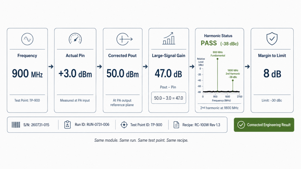
Frequency → Source Setting → Actual Pin → Corrected Pout → Large-Signal Gain → Harmonic Status → Margin to Limit
Actual Pin Must Remain Visible
The signal-generator setting is not always equal to the power delivered to the PA input.
Passive source-path components may introduce frequency-dependent loss. An active driver may also change with frequency, input level, compression, supply condition, and temperature.
Actual Pin should therefore come from:
- measurement at the PA-input reference plane; or
- a controlled and validated method appropriate to the source path.
This allows the production record to reveal:
- which frequency required the highest input;
- where large-signal gain was lowest;
- whether output was recovered by increasing drive;
- whether the approved Pin boundary was approached;
- whether the customer’s SDR or driver can reproduce the condition.
Large-signal gain is calculated from connected values:
Large-Signal Gain = Corrected Pout − Actual Pin
Harmonics Must Match the Same Output State
A harmonic result is useful only when it can be connected to the fundamental frequency and output condition under which it was measured.
The power record or linked spectrum record should identify:
- fundamental frequency;
- actual Pin;
- corrected Pout or validated fundamental level;
- measured harmonic frequency;
- corrected harmonic result;
- dBc result;
- acceptance limit;
- margin to limit.
The power and spectrum records may remain in separate tables if they share:
- module S/N;
- run ID;
- test-point ID;
- fundamental frequency;
- recipe version.
PASS Is Not Enough Without Margin
A result that passes by 0.2 dB does not provide the same production margin as a result that passes by 8 dB.
The record should therefore preserve the distance from the applicable limit for:
- Pin;
- Pout;
- gain;
- current;
- harmonic performance.
Where a project uses a measurement guard band, the report or release rule should also state how that guard band affects PASS, REVIEW, or FAIL status.
Margins make it possible to identify a production shift before units begin to fail.
The production record should preserve frequency, input drive, corrected output, gain, harmonic status, and margin as one connected engineering result.
5. What Should Happen When One Unit Falls Outside the Test Window
The quality of a production test process is revealed most clearly when a module does not pass.
A controlled response should follow a defined path:
Out-of-Limit Result → Connection Check → Test-Path Verification → Controlled Retest → Engineering Review → Rework or Reject → Final Reverification
Check the Connection and Test Path
The first review should determine whether the result came from the module or the test setup.
The operator may inspect:
- RF connector seating;
- DC and load connections;
- fixture condition;
- cooling contact;
- cable routing;
- recipe and correction versions.
This check must not erase the initial result.
Preserve the Controlled Retest
A retest should record:
- the initial result;
- reason for retest;
- changed condition;
- new result;
- final disposition.
The first failed result should not disappear because a later run passed.
Prevent Informal Adjustment
The operator should not:
- increase Pin outside the approved algorithm;
- lower the acceptance limit;
- delete a failed record;
- replace a correction file without recording the change;
- substitute data from another unit;
- release a reworked module using its pre-rework report.
If the module remains outside the window, engineering review should decide whether it requires inspection, authorized adjustment, rework, expanded reverification, or rejection.
Changes in thermal contact, torque, shielding, grounding, harness routing, connector fixation, cleaning, or test setup can affect batch behavior even when the model and schematic remain unchanged. A review of RF PA process changes should connect the change to the affected path, S/N range, validation scope, and release evidence.
Any adjusted or reworked module should complete the required verification sequence again. Its final report must represent the post-adjustment condition.
A controlled production test is defined as much by its response to an abnormal result as by its normal PASS sequence.
6. What Batch Evidence Should Be Available Before Shipment
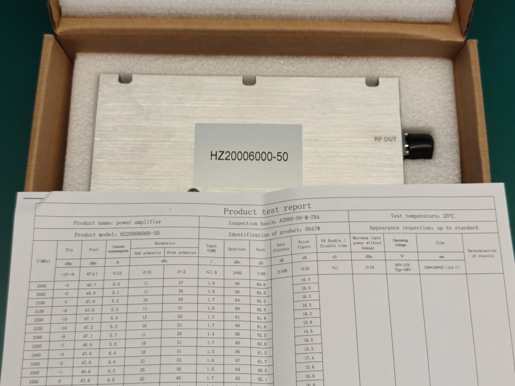
For batch production, every delivered RF PA should have its own automated, S/N-linked production test report.
The golden-sample approval record documents the approved starting point. Internal batch review identifies population-level changes. Neither replaces the individual report for each shipped module.
What the Customer-Facing Report Must Answer
A useful RF PA test report before shipment should allow the customer to answer four questions:
- Which module was tested?
- Which frequency points, input method, and recipe were used?
- What results and margins were recorded under the defined boundaries?
- Why was the module released?
The report should identify the individual S/N, controlled configuration, tested frequencies, actual Pin, corrected Pout, gain, applicable harmonic results, DC condition, test state, retest status where relevant, and final release conclusion.
Internal Batch Trends Must Lead to Defined Actions
An individual PASS report answers whether one unit met the requirement. It does not show whether the batch is gradually moving toward a limit.
Internal production review should monitor:
- first-pass yield;
- retest rate;
- Pout and gain distributions;
- actual Pin required at each frequency;
- current outliers;
- harmonic margin;
- repeated anomalies by batch, station, or recipe version.
These trends should be evaluated against predefined warning and action criteria.
A trend may trigger:
- test-station verification;
- fixture or correction review;
- component-lot review;
- process inspection;
- expanded frequency testing;
- engineering review;
- temporary shipment hold.
A production trend should not be attributed to the modules until the station condition, fixture state, calibration status, and correction versions have been checked.
For example, a gradual increase in required Pin may indicate declining module gain. It may also come from increased source-path loss or a station correction error. The test system must be reviewed before the product process is blamed.
Detailed batch statistics may remain supplier-controlled production data. They should still support internal batch release and be available where a higher-traceability project defines that requirement.
RFQ Checklist for Batch-Consistency Evidence
| RFQ item | What to provide or request | What it confirms |
| Approved baseline | Golden-sample approval or controlled configuration reference | Production starts from an approved design state |
| Configuration control | Model, hardware revision, BOM status, firmware, and permitted production adjustments | The product state and adjustment limits are controlled |
| Test recipe | Recipe version, applicable S/N range, frequencies, input algorithm, and acceptance limits | Every unit follows an approved verification logic |
| Test-station control | Station ID, fixture version, calibration status, correction version, and station-correlation status | Results remain comparable across production stations |
| Frequency-point evidence | Frequency, actual Pin, corrected Pout, gain, harmonic status, and margin to limit | Input, output, and spectrum behavior remain connected |
| Out-of-limit procedure | Retest, engineering review, rework, rejection, and reverification rules | Failed results cannot be handled informally |
| Unit-level report | One automated S/N-linked report for every delivered RF PA | Each shipped module has its own acceptance evidence |
| Supplier batch-release control | Confirm that yield, retest rate, result margins, and abnormal trends are reviewed against controlled internal criteria; detailed data available where project-defined | Batch release is not based only on individual PASS labels |
| Final release | Unit result, exceptions, and controlled approval status | Every module has a defined shipment decision |
Automated test data supports scalable production control; batch trends reveal drift, and one S/N-linked report proves the acceptance result for each delivered RF PA.
Conclusion
A golden sample passing is the beginning of production control, not the end.
Automated RF PA testing protects batch consistency by applying a controlled recipe, maintaining comparable test stations, exposing unit and batch variation, preserving abnormal-result history, and generating one S/N-linked report for every delivered module.
RF SKYPOWER can support early engineering review of the approved frequency map, Pin method, Pout limits, harmonic requirements, station-correlation method, test-path corrections, recipe version, cooling boundary, out-of-limit rules, batch-warning criteria, and unit-level report format before production begins.