










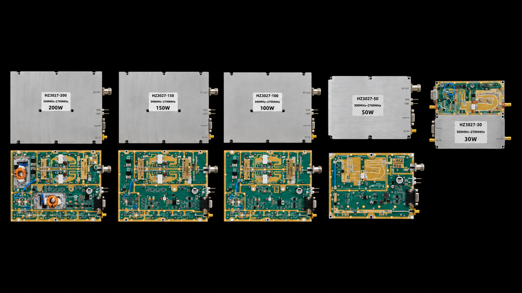
RF SKYPOWER’s 300-2700 MHz PA specs cover a standard 30W–200W RF power amplifier family for projects with widely separated operating frequencies. The family spans 2.4 GHz from 300 MHz to 2700 MHz, while the current maximum instantaneous bandwidth is 200 MHz.
The main advantage is not simply that the upper limit reaches 2700 MHz. It is that several widely separated operating points can stay inside one product family. To use that advantage correctly, first define the project’s real frequency set, then separate the 2.4 GHz operating span from the 200 MHz maximum instantaneous bandwidth, and finally identify which frequencies need the strongest performance evidence.
1. Why 300–2700 MHz Is a Different Wideband Design Problem
A 300–2700 MHz project is better treated as a distributed frequency-set problem than as one conventional RF band.
The important operating points may be separated by hundreds of megahertz, yet all belong to the same system. If those frequencies extend across a large part of 300–2700 MHz, one HZ3002700 family can provide a common starting platform instead of forcing the project to begin with several different frequency-range amplifier families.
That can simplify product-family planning, sourcing, mechanical planning, and later power-class selection.
The key question is therefore:
Does the project’s actual frequency set justify one 300–2700 MHz product family?
If the answer is yes, define those operating points before comparing 30W, 50W, 100W, 150W, or 200W models.
A wider family can reduce the number of product families under consideration, but the frequencies that matter still need to be evaluated individually. If the project has not yet decided whether it really needs 300–2700 MHz rather than a narrower range, that broader decision belongs to wideband RF power amplifier selection.
2. 2.4 GHz Operating Span Is Not 2.4 GHz Instantaneous Bandwidth
The HZ3002700 family is published for:
300–2700 MHz
The distance between those endpoints is:
2700 MHz − 300 MHz = 2400 MHz = 2.4 GHz
For this family, RF power amplifier instantaneous bandwidth is specified at up to 200 MHz.
| Specification | Meaning |
|---|---|
| Operating range | 300–2700 MHz |
| Operating span | 2.4 GHz between the published endpoints |
| Maximum instantaneous bandwidth | 200 MHz of spectrum handled at one time |
The operating range tells you where the amplifier can operate; instantaneous bandwidth tells you how much spectrum it handles at one time.
A project should therefore define two separate inputs: the frequencies where RF output is required and the maximum signal bandwidth required at one time.
3. Why Band Edges and Priority Frequencies Matter More as the Range Widens
Once the frequency set is known, the next step is to identify the priority frequencies—the operating points that actually drive the system decision.
Some may sit close to the lower 300 MHz edge. Others may approach 2700 MHz. For this family, RF amplifier frequency response matters at every project priority frequency, including interior points with higher power, limited drive, or demanding thermal conditions.
For each priority frequency, define the conditions that matter:
| Priority-Frequency Input | What to Define |
|---|---|
| Frequency | Actual required operating point |
| Pout | Required RF output |
| Pin | Available RF input |
| Signal condition | CW, pulsed, modulated, or other defined waveform |
| Duty condition | Actual operating duty |
| Load | Intended RF load or downstream condition |
| Thermal state | Required operating condition |
| Output reference plane | RF point where Pout is defined |
The output reference plane is especially important. Pout defined at the PA output connector is not the same as power measured after cable, switch, filter, or fixture loss.
This is the most useful way to work with a 2.4 GHz operating span: do not treat the entire range as one abstract block. Identify the frequencies that actually make or break the project.
A project may care about only four widely separated frequencies. Another may require many points across a broad section of the range. Both can use the same 300–2700 MHz family, but they do not need the same verification scope.
Priority-frequency mapping also improves comparison. Before comparing two Pout or Gain results, align the important conditions:
Frequency + Pin + Pout reference plane + waveform + duty + load + thermal state
If the project ultimately requires minimum performance across the complete operating set rather than selected priority points, the same frequency map becomes the starting point for full-band RF power amplifier performance verification.
4. 30W–200W Standard Models at a Glance
Once the frequency set fits the 300–2700 MHz family, use power, current, dimensions, and RF interfaces to narrow the standard models.
300–2700 MHz Standard Models
Click a model card to open its PDF datasheet · Swipe horizontally →
| Power Class | Model | Psat Min / Typ | Operating Current Typ / Max | Dimensions | RF Input / Output | Control Interface |
|---|---|---|---|---|---|---|
| 30W |
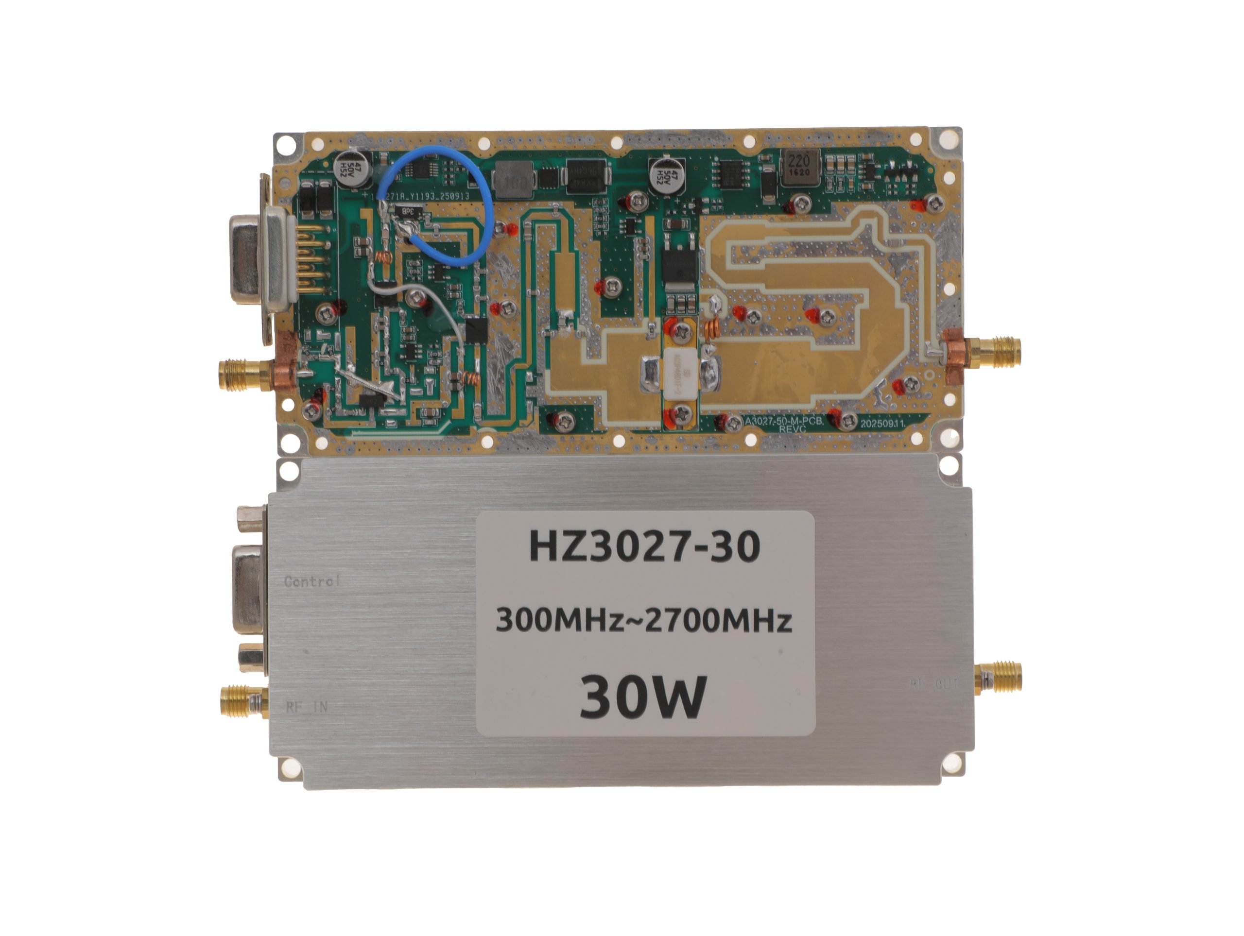 HZ3002700-30NA1View PDF ↗ |
25 / 30 W | 3.2 / 4 A | 125 × 59 × 21.5 mm | SMA-KFD46 / SMA-KFD46 | D-Sub 9-Pin |
| 50W |
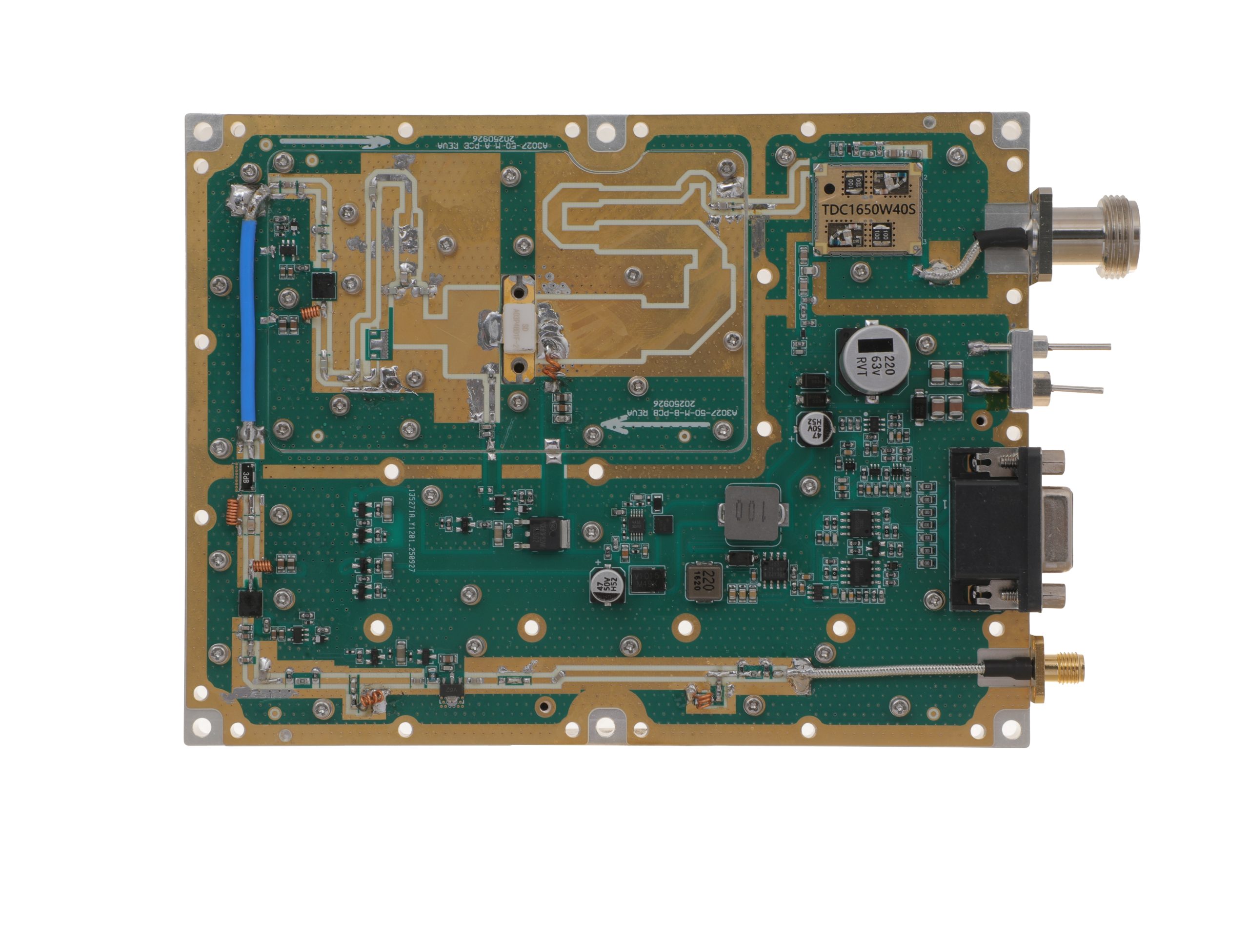 HZ3002700-50NA1View PDF ↗ |
40 / 50 W | 7.2 / 9 A | 160 × 120 × 25 mm | SMA-F / N-F | D-Sub 15-Pin |
| 100W |
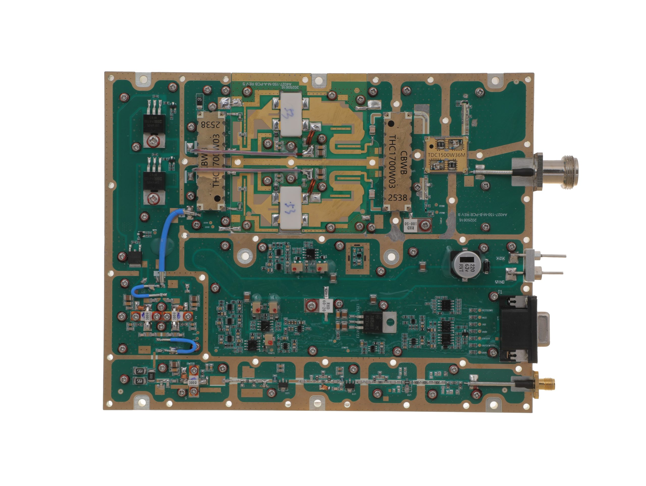 HZ3002700-100NA1View PDF ↗ |
80 / 100 W | 14.5 / 18 A | 200 × 158 × 25 mm | SMA-F / N-F | D-Sub 15-Pin |
| 150W |
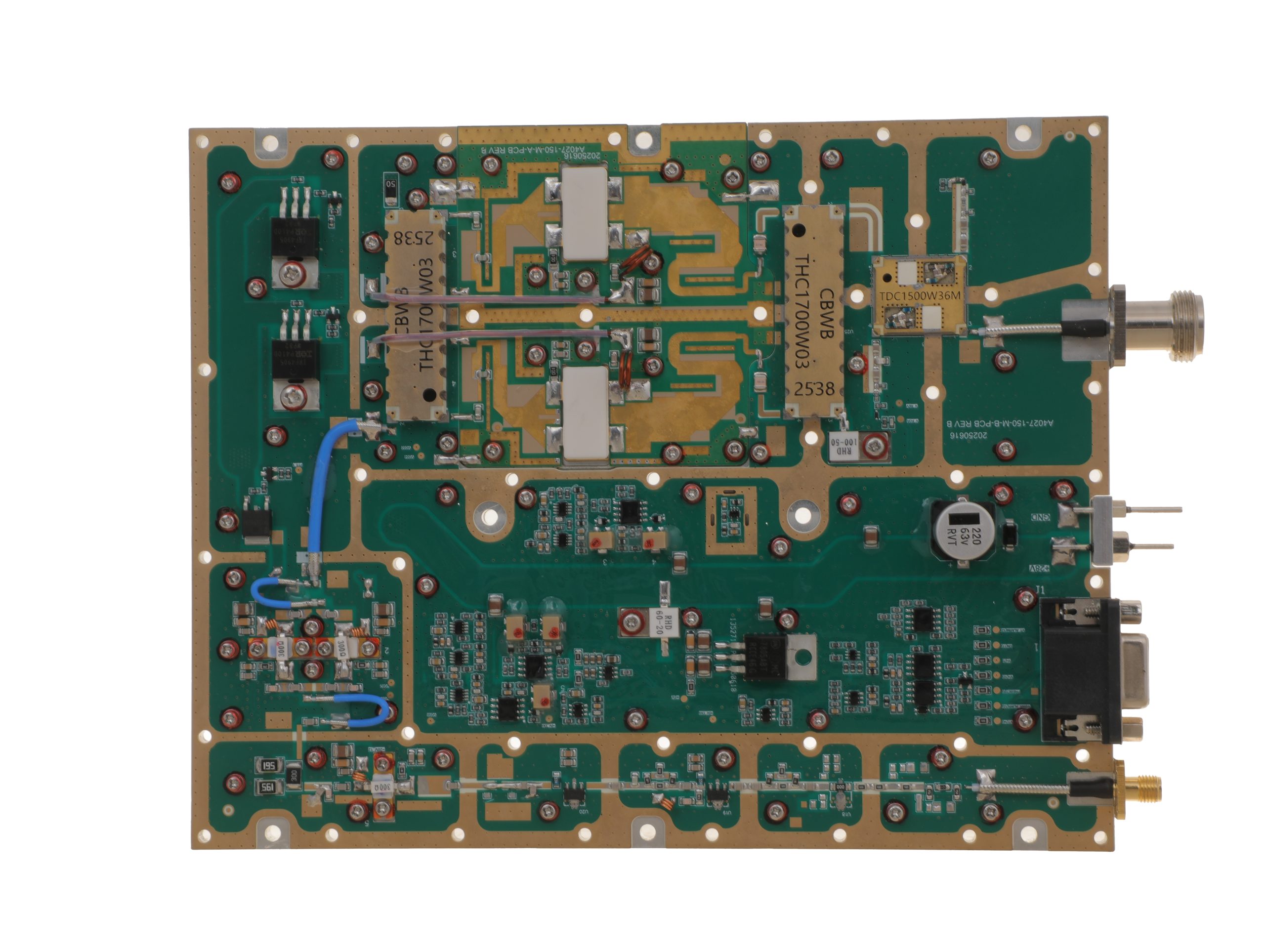 HZ3002700-150NA1View PDF ↗ |
120 / 150 W | 16 / 20 A | 200 × 158 × 25 mm | SMA-F / N-F | D-Sub 15-Pin |
| 200W |
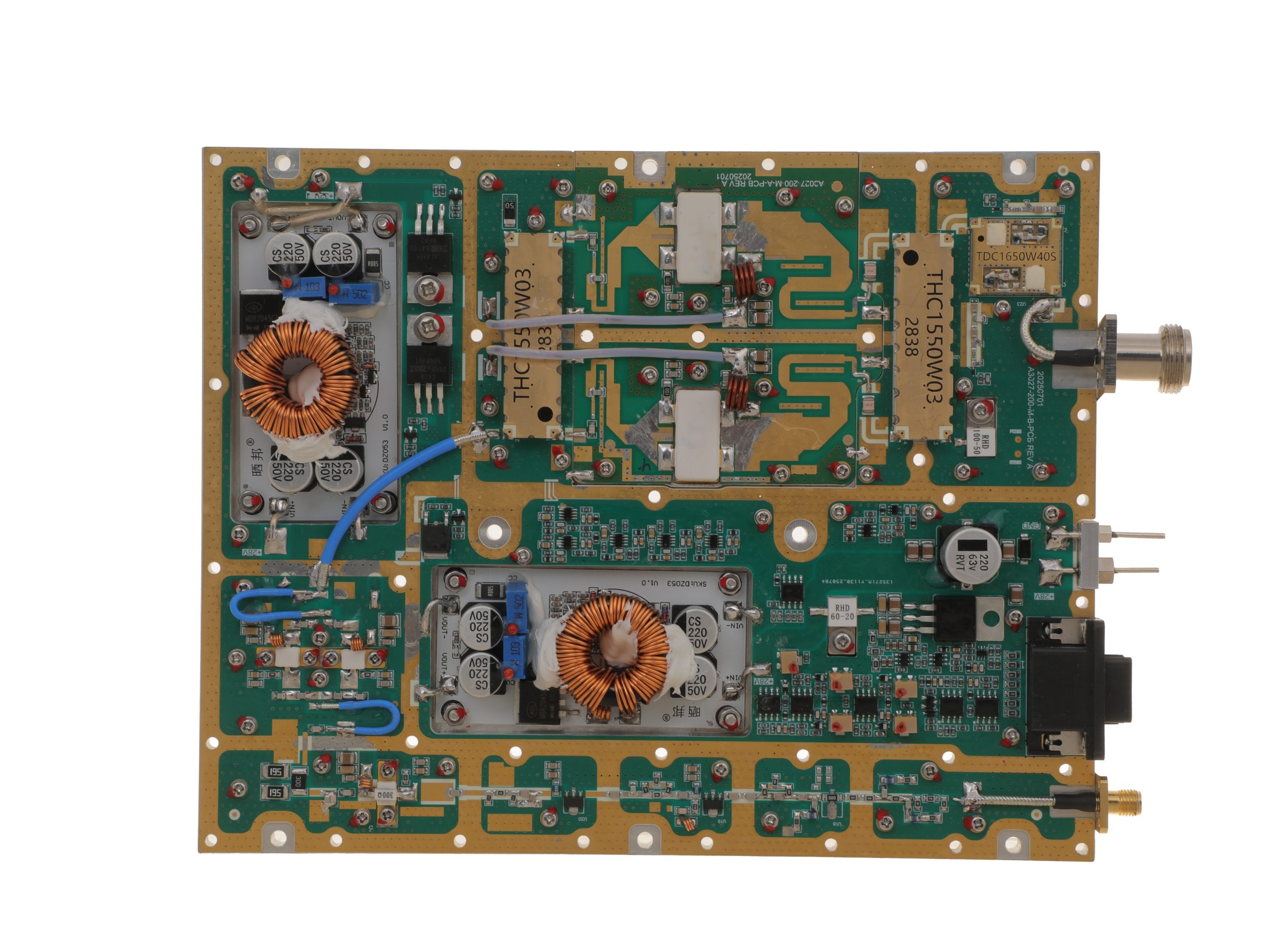 HZ3002700-200NA1View PDF ↗ |
160 / 200 W | 29 / 36 A | 200 × 158 × 25 mm | SMA-F / N-F | D-Sub 15-Pin |
The Psat figures are minimum / typical values under CW conditions. After the required power level is known, available DC current, chassis space, and RF interfaces can quickly reduce the five choices to the relevant models.
Detailed model specifications are available for the 300-2700 MHz RF power amplifier family.
5. Match the Verification Scope to Your Required Frequencies
A wide operating range does not mean every project needs the same amount of testing.
The better rule is:
Requirement scope → verification scope
If the project only needs an initial model shortlist, the published model specifications are the natural starting point.
If several frequencies are critical, verify those priority points.
If operation near 300 MHz or 2700 MHz matters, add the relevant band-edge conditions.
If the acceptance requirement applies across the entire required range, expand the work into full-band verification.
| Project Requirement | Appropriate Verification Scope |
|---|---|
| Initial model selection | Published model specifications |
| Several critical operating frequencies | Priority-frequency results |
| Critical lower- or upper-edge operation | Band-edge evidence |
| Defined wideband waveform | Waveform-specific performance evidence |
| Defined hot-state requirement | Performance under the required thermal condition |
| Minimum performance across the complete required range | Full-band verification |
This keeps the engineering effort proportional to the real project requirement.
For example, a system using four widely separated frequencies does not automatically need the same evidence package as a project requiring a defined minimum Pout across the entire 300–2700 MHz range.
The important point is to decide how much of the frequency set must be proven, and under which conditions.
The published specifications provide the model-selection baseline. Project evidence can then focus on the frequencies, waveform, Pin, Pout, reference plane, and thermal state that actually affect the acceptance decision.
When the requirement extends across many priority frequencies or the full operating range, full-band RF power amplifier performance verification becomes the appropriate next engineering step.
6. Standard Model, Full-Band Engineering Review, or Custom RFQ?
By this point, the project should already have three things defined: the required frequency set, the approximate power class, and the level of performance evidence needed. Those three inputs are enough to decide which route makes sense.
Standard Model
Stay with the standard-model route when the required operating frequencies fall within 300–2700 MHz, one of the published 30W–200W power classes fits the project, and the standard mechanical and RF-interface configuration is acceptable.
At this stage, the job is straightforward: narrow the family by Pout, available DC current, dimensions, and RF connectors, then review the corresponding model specification.
Full-Band Engineering Review
Move into engineering review when the open question is no longer “Which model fits?” but “What performance must be demonstrated across my actual frequency set?”
This route is appropriate when the project depends on multiple priority frequencies, operation near 300 MHz or 2700 MHz, fixed Pin, hot-state performance, a defined wideband waveform, or a minimum Pout / Gain requirement across a broader part of the range.
The verification scope should follow the requirement: selected priority points when only those points matter, or a broader full-band test when the acceptance requirement applies across the full operating set.
Custom RFQ
Use the custom route when the project itself falls outside the standard product boundary—for example, the required frequency range, output power, mechanical format, or RF interface cannot be satisfied by the published models.
A custom RFQ should therefore describe the requirement that remains unresolved, not repeat every specification already covered by a standard model. The purpose is to let engineering determine whether a non-standard configuration is practical for the project.
Conclusion
The main advantage of a 300–2700 MHz RF power amplifier family is the ability to cover widely separated operating frequencies within one standard 30W–200W product platform. For systems that span multiple RF regions, this can simplify product planning and integration without forcing each frequency range into a separate amplifier family.
The 2.4 GHz operating span and 200 MHz maximum instantaneous bandwidth should be treated as separate specifications. Define the actual operating frequencies first, then identify the priority and band-edge points that matter most. That frequency set can be used to narrow the power class and determine where additional project evidence is required.
If the standard frequency, power, mechanical, or RF-interface options do not fit the project, submit the remaining requirements through a custom RF power amplifier RFQ.