










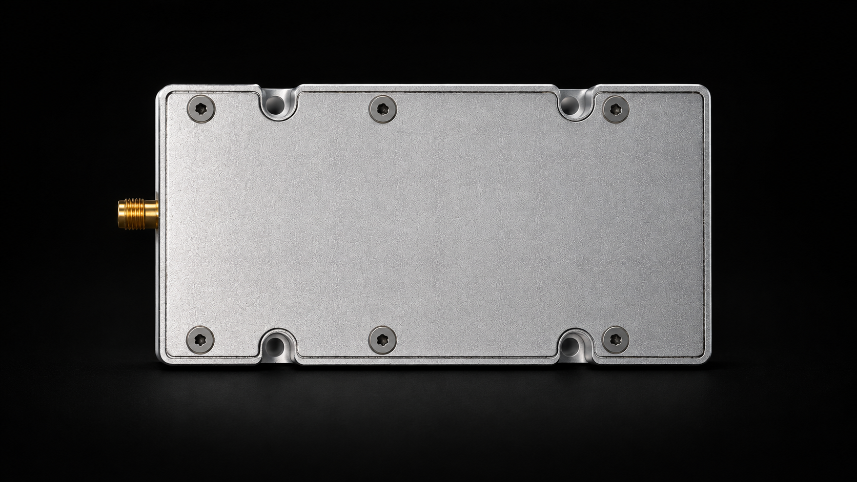
An SDR signal source meets a dual-output requirement when both RF ports deliver their assigned waveforms at the same time, within the project’s bandwidth, leakage, spectral-quality, and control limits. Measure both ports under the frequency pairs and output states the system will use.
Two RF SKYPOWER models cover 100–6000 MHz but have different external RF-port arrangements. Their SDR signal-source module specifications are summarized below.
Swipe horizontally to view all columns.
| Model | Frequency Range | Physical RF Outputs | Real-Time Bandwidth | Control Interface | Acceptance Note |
|---|---|---|---|---|---|
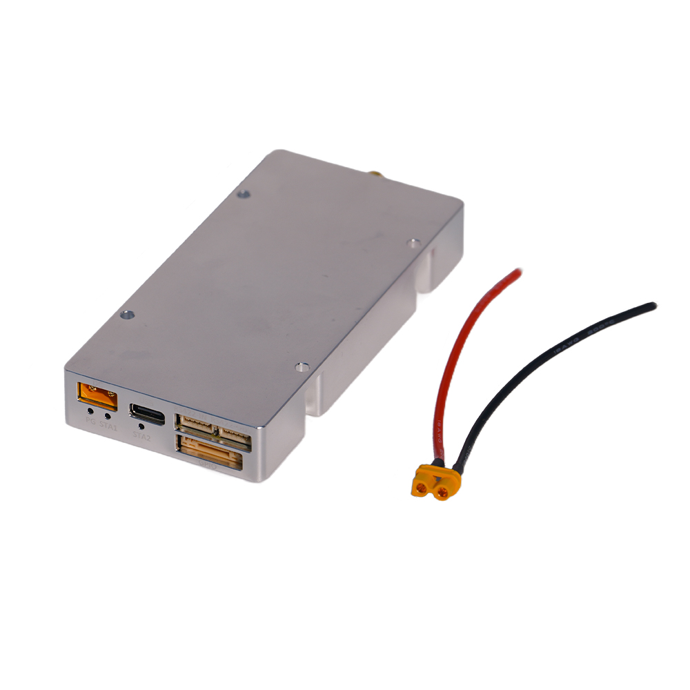 HZS1006000-F1
View PDF Datasheet |
100–6000 MHz | One external SMA RF output; internal dual-PHY architecture | Up to 200 MHz real-time bandwidth | RS422, model-specific AT commands | Establish the external RF routing for the intended single-port or expanded configuration. |
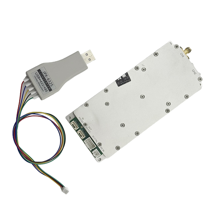 HZSDR1006000-A01
View PDF Datasheet |
100–6000 MHz | Two independent SMA RF outputs | Up to 100 MHz per channel; 200 MHz combined nominal capacity across two outputs | RS422 and host-side configuration | Verify simultaneous output and channel-by-channel control at both SMA ports. |
1. What Counts as Two Independent RF Outputs in an SDR Signal Source?
A dual-output source gives the integrator two accessible RF connectors, each assigned to a defined signal path and channel. Dual-PHY describes internal processing resources; the external port map shows how those resources reach the system.
Operational independence means each port retains its assigned frequency, waveform, level, and output state while the other channel changes.
Request a connector map for the exact hardware revision, the channel-to-port assignment, and representative RF captures from both SMA interfaces. If the application depends on shared clocks, local oscillators, or converters, include those resources in the architecture review.
2. How Should Bandwidth Be Allocated Across Two SDR Outputs?
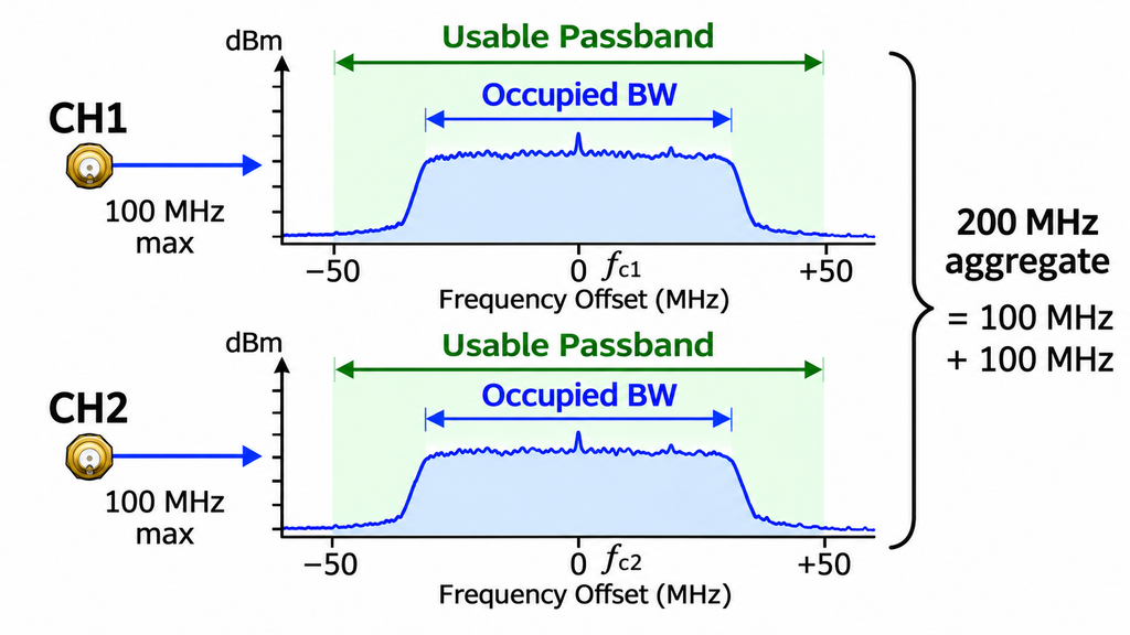
Allocate bandwidth per RF port. On the HZSDR1006000-A01, 200 MHz combined capacity means two nominal 100 MHz channel budgets, one per SMA connector. It does not describe a single contiguous 200 MHz RF output.
Real-time bandwidth is the frequency span a channel can generate simultaneously. Occupied bandwidth describes the spectrum used by the selected waveform. Check both the available passband and the signal’s measured spectrum.
Build a frequency-pair plan around the application. Include priority pairs, widely separated channels, nearby channels where relevant, and band-edge cases. For each pair, specify the center frequency, waveform occupied bandwidth, and output level at both ports.
For each required pair, capture the two RF outputs during simultaneous operation. Record the configured bandwidth, available sample-rate information, measured occupied bandwidth, usable passband, and any relevant flatness or spectral-quality limit.
3. Which Dual-Channel States and Waveforms Must Be Tested?
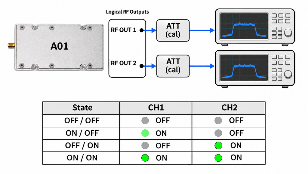
Test four output states on a conducted 50-ohm setup with rated terminations, calibrated attenuation, and defined SMA reference planes. Hold frequency and power settings constant when comparing states.
| Test State | Channel 1 Configuration | Channel 2 Configuration | Measurement Port | Main Measurements | Result Record |
|---|---|---|---|---|---|
| Both disabled | RF output disabled | RF output disabled | SMA 1 and SMA 2 | Residual RF levels and disabled-state behavior | Baseline traces and configuration log |
| Channel 1 active | Defined frequency, waveform, and level | RF output disabled | SMA 1 and SMA 2 | Channel 1 signal; leakage at SMA 2 | Corrected per-port levels and paired captures |
| Channel 2 active | RF output disabled | Defined frequency, waveform, and level | SMA 1 and SMA 2 | Channel 2 signal; leakage at SMA 1 | Corrected per-port levels and paired captures |
| Both active | Required frequency and waveform A | Required frequency and waveform B | SMA 1 and SMA 2 | Per-port output, occupied bandwidth, spurs, and coupling | Simultaneous-condition traces and test IDs |
Use a CW signal to establish straightforward power and leakage readings, then repeat the relevant states with the application’s modulated waveforms. Save the channel settings, power metric, cable-loss corrections, analyzer settings, and observation interval with each capture.
4. How Do You Measure Channel Isolation and RF Leakage?
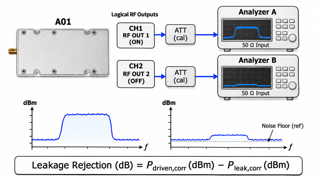
Begin with one channel active and the other disabled. Measure the intended RF signal at the driven SMA connector, then measure the same signal component at the other SMA connector. Correct both readings for their respective cable and attenuation paths.
Leakage rejection (dB) = corrected signal power at the driven SMA port (dBm) − corrected leakage power at the other SMA port (dBm).
Repeat the measurement with the channels reversed, then at the required frequency pairs and output settings. Record both directions separately. When leakage falls below the corrected analyzer noise floor, report the minimum demonstrated rejection as a lower bound and retain the analyzer settings and floor reading.
During the both-active test, use distinguishable carriers or waveform markers to identify coupling into the other port’s spectrum. Compare the results against the project’s isolation and spectral limits.
5. What Changes in Power, Spurs, and Spectral Quality When Both Outputs Are Active?
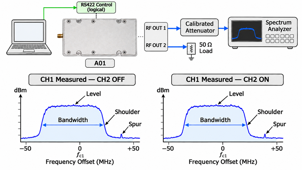
Keep Channel 1 at a fixed frequency, waveform, and level. Compare its corrected RF power with Channel 2 disabled and enabled. Reverse the comparison for Channel 2. Report the power change at each SMA port in dB.
For the same two conditions, compare occupied bandwidth, spectral shoulders, harmonics, nonharmonic spurs, and cross-channel products. Measure modulation quality when the waveform has an agreed metric. Check analyzer headroom before attributing a new spur to the SDR.
During the agreed sustained-operation interval, record supply voltage, current, elapsed time, and relevant thermal conditions alongside both RF outputs.
For systems with an external power amplifier, these readings establish the SDR output reference for SDR-to-PA integration testing.
6. Can Each Output Be Controlled and Restored Independently?
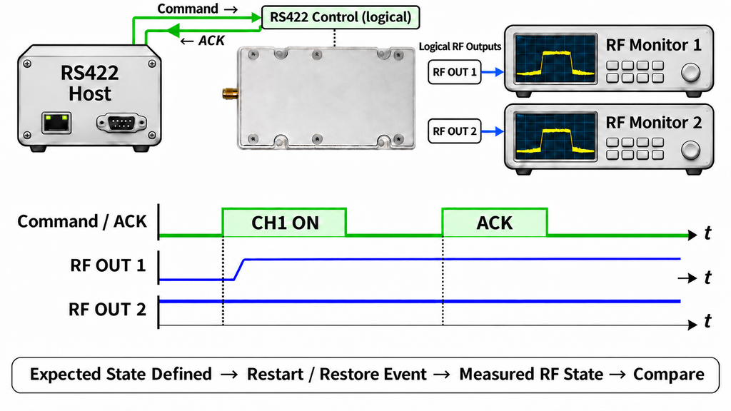
Send a command to one channel while the other remains active. Log the controller response and measure both SMA ports. Repeat for output enable, center frequency, waveform, and level changes. Capture the commanded channel’s response time and any change at the other connector. The command acknowledgment shows what the controller accepted; the RF trace shows what the source delivered.
Use the current F1 AT-command reference for F1 tests and the A01 host-control reference for A01 tests. Include the hardware and firmware revisions in the command log.
Finish with the required restart cases, such as a power cycle or controller restart. Define the expected initial output state and recovery-time endpoints before testing. Measure the time from the specified restart event or restore command to the expected RF state at each SMA port.
7. What Evidence Is Enough to Accept a Dual-Output SDR Signal Source?
Set the numerical limits and required operating conditions before the supplier trial. The worksheet below summarizes the acceptance decision; the complete frequency-pair matrix, instrument records, and per-port captures remain in the referenced test reports.
Enter corrected readings, units, and test IDs in Measured Result. The final two columns are left open for the actual trial.
| Acceptance Item | Test Conditions and Reference Plane | Required Evidence | Agreed Limit | Measured Result | Decision |
|---|---|---|---|---|---|
| Physical output architecture | Approved hardware revision; both SMA interfaces | Connector map and channel-to-port RF captures | Two assigned, independently controllable RF ports | ||
| Bandwidth per channel | Required center frequencies and waveforms; each SMA | Per-port usable passband and occupied-bandwidth captures | Required usable bandwidth per port | ||
| Simultaneous bandwidth | Both outputs active at approved frequency pairs | Concurrent per-port bandwidth and spectrum records | Channel 1 and Channel 2 limits met together | ||
| Output-state behavior | Both off; each channel alone; both active | Four-state traces and corrected levels | Agreed state-dependent output and leakage limits | ||
| Channel leakage rejection | Both directions; specified frequencies and levels | Corrected driven/leakage power, analyzer floor, test ID | Minimum rejection in dB per direction | ||
| Both-active spectral quality | Required CW and modulated waveforms; each SMA | Power change, spurs, occupied bandwidth, and applicable waveform metrics | Allowed per-port power shift and spectral limits | ||
| Independent control | Channel-specific commands with opposite channel held constant | Command log, response timing, and paired RF traces | Approved control behavior and timing limits | ||
| Restart and restoration | Defined restart events and initial RF states | Per-port startup state, recovered settings, and time record | Required states and maximum recovery time | ||
| Traceability | Unit serial number, hardware/firmware revision, test setup | Linked raw captures, corrections, instrument settings, and report IDs | Complete agreed evidence package |
Mark Pass when a result meets the agreed limit and links to its test record. Use Fail for a measured limit breach and Hold for a missing record or defined retest. Give each retest its own ID and preserve the original conditions for comparison.
Conclusion
The combined-bandwidth figure helps shortlist sources. Final acceptance rests on the recorded results at both SMA ports under the required simultaneous operating conditions.
For an RF SKYPOWER engineering review, send us the required frequency pairs, each channel’s waveform and occupied bandwidth, RF levels, control interface, supply and thermal conditions, hardware revision, and acceptance limits. Our engineers can review these inputs against the HZSDR1006000-A01 dual-output route and the proposed source configuration.