










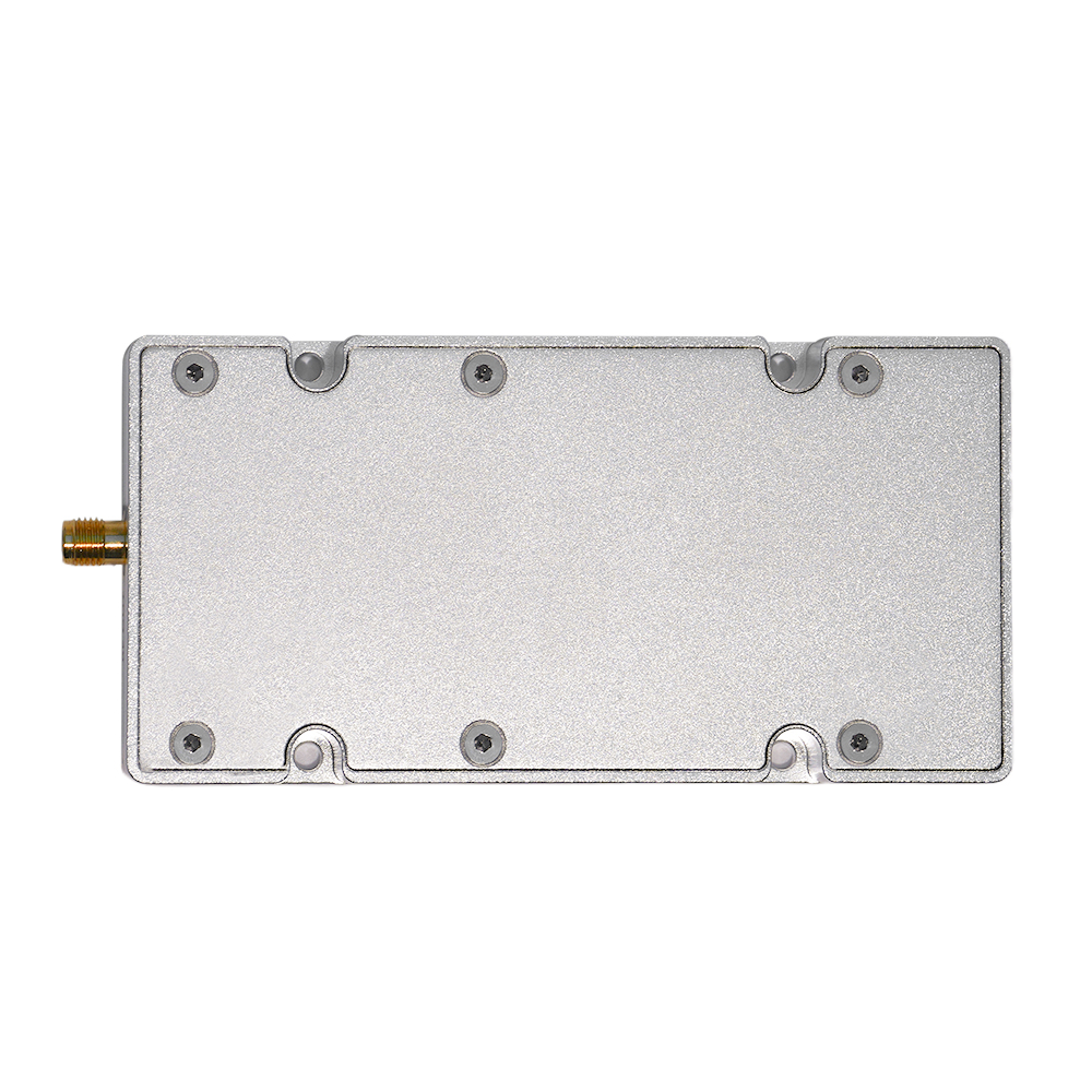
Accepting SDR phase coherence requires measured inter-channel RF phase results against project limits at defined frequencies, waveforms, output reference planes, and operating states. A shared reference clock sets a frequency basis, and synchronized commands coordinate operations; the RF phase relationship still needs measurement.
First decide what the application needs: a fixed phase offset, stability during operation, repeatability after a state change, or a combination. That choice determines the measurements to request.
The published RF SKYPOWER SDR signal-source module range includes the following RF transmit/source modules relevant to multi-channel evaluations:
| SDR RF signal-source module | Published frequency range | Published real-time bandwidth | Control interface |
|---|---|---|---|
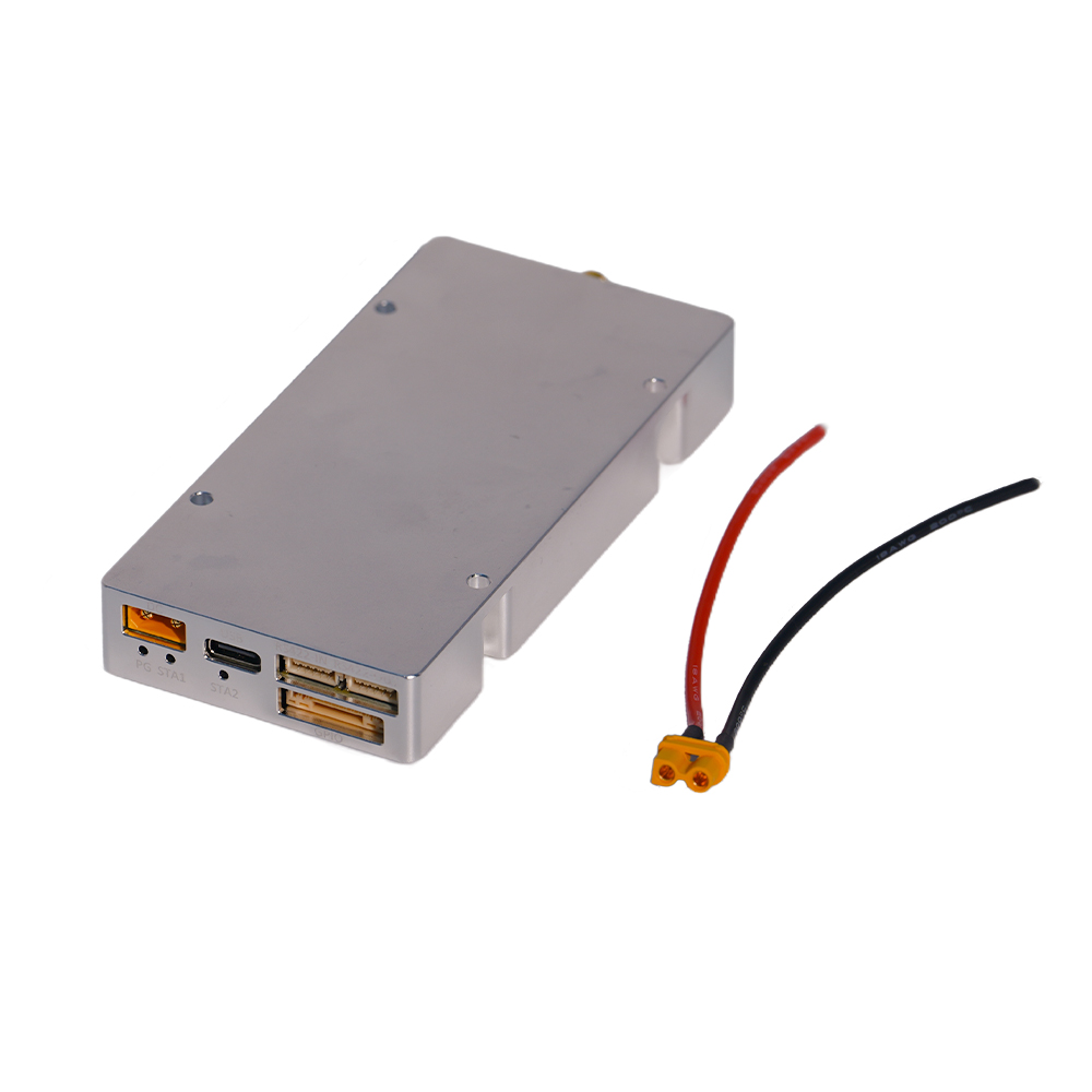
HZS1006000-F1
View PDF Manual
|
100–6000 MHz | Up to 200 MHz (published maximum) | RS422 / native API |
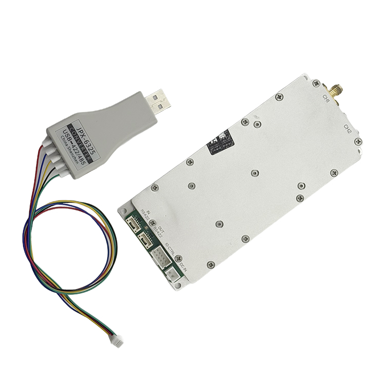
HZSDR1006000-A01
View PDF Manual
|
100–6000 MHz | 100 MHz (200 MHz combined, as published) | RS422 / native API |
The HZSDR1006000-A01 manual identifies two independent external SMA RF outputs. The HZS1006000-F1 manual describes dual-PHY control but documents one external SMA RF output. For an F1-based multi-channel test, confirm the physical RF-port routing or proposed multi-unit configuration before defining channel pairs.
These published figures describe frequency coverage, bandwidth, and control. The F1’s 200 MHz figure is a published maximum, with per-channel allocation and phase-coherent bandwidth to be verified for the proposed configuration. RS422 cascading supports control; inter-unit phase acceptance also calls for the RF reference arrangement and measured phase results. Request the applicable API details for the hardware and firmware under review.
1. What Does Phase Coherence Mean for a Multi-Channel SDR Source?
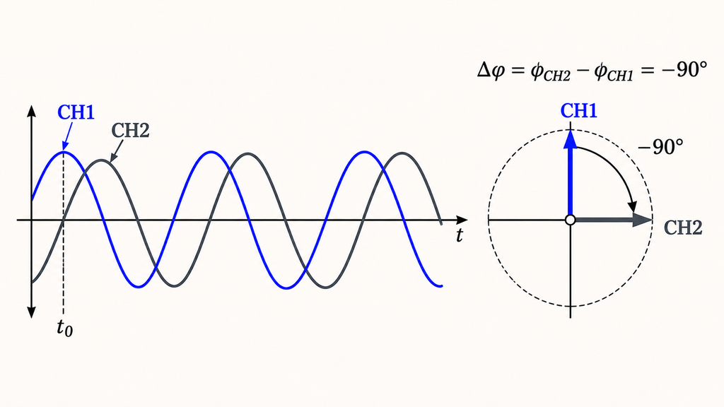
For acceptance, phase coherence is a specified relationship between RF output phases that stays within limits during operation or returns to those limits after an allowed recovery procedure.
Separate four properties in the acceptance requirement:
- Frequency synchronization: Channels maintain the specified carrier-frequency relationship within an agreed tolerance. Their relative RF phase is a separate measurement.
- Time alignment: Events or samples share a time basis; a common trigger alone need not align carrier phase.
- Relative phase offset and stability: At one carrier frequency and common observation time, measure a channel’s phase against a named reference. Initial offset and subsequent change are distinct quantities.
- Restart repeatability: The required relationship returns after a specified restart, retune, or configuration event. Stable operation during one run does not guarantee the same starting phase in the next.
An application that permits phase recalibration after startup has a different requirement from one demanding a repeatable phase immediately after power-up. State which applies.
For different carrier frequencies, raw phase difference naturally evolves because the carriers rotate at different rates. Specify a frequency-dependent phase response, relative timing or delay, or another waveform-specific metric instead of demanding a constant same-carrier phase offset. Wideband modulation may require measurements across the signal bandwidth, not just its center.
Before testing, define the metric and limit, channel pairs, waveform, observation window, and recalibration policy. If the carrier relationship or limit is unclear, the result cannot be judged against a meaningful requirement.
2. What Reference Setup Is Required for a Valid Phase Measurement?
Connect each physical SDR RF output to a separate channel of a phase-coherent measurement receiver, or an equivalently validated setup. Document the cables, attenuators, switches, and fixtures. Characterize the receiver’s inter-channel phase response, reference timing, and drift; include their contribution in the uncertainty.
Record each SDR channel’s RF output-level setting and the level at the measurement receiver input. Compare results at matched levels, or document level-dependent phase behavior where it affects the comparison. Keep receiver inputs within their calibrated ranges and check signal-to-noise ratio at each frequency.
For same-carrier tests, use a defined CW or pilot signal, or another waveform with a known inter-channel phase relationship. Record the programmed baseband or I/Q phase offset and waveform-start state. This helps distinguish RF-path phase error from an offset introduced when the waveform starts.
A reference clock governs frequency relationships; a sampling clock sets conversion timing; a trigger or time reference coordinates events or sample epochs. RF local-oscillator (LO) phase is different. It may depend on architecture and startup or retuning state, even with a shared clock. Request the offered configuration’s actual synchronization method rather than assume a common LO or phase-alignment mechanism.
The RF output reference plane is each SDR connector’s specified mating plane, where the accepted phase relationship is defined. The receiver measures downstream of cables and other paths that can introduce differential phase shifts. Those shifts need to be measured and removed or accounted for, not assigned to the source.
Retain the connection diagram, reference and trigger settings, instrument identity, calibration status, and frequency-dependent path corrections. A common-source reference measurement, or documented equivalent, can distinguish fixture phase from SDR output phase. Preserve original and corrected readings with their sign convention; verify that instrument corrections have not been applied twice.
Compare reports only when reference planes, source states, receiver alignment, and corrections match or can be reliably normalized. If the output reference plane or correction is unknown, hold the quantitative phase verdict.
3. What Should Phase-versus-Time and Phase-versus-Frequency Results Show?
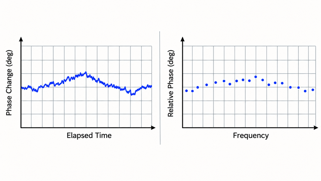
A single screenshot captures phase at one instant. Use a time trace to assess stability and measurements across the frequency grid to assess band-dependent behavior.
For same-frequency outputs, measure inter-channel relative phase against a named reference channel at common observation times. Establish the initial offset at a defined baseline after startup and settling. Phase drift is its subsequent change over the observation window. A limit on absolute offset differs from one on change relative to the baseline; specify which applies.
Record carrier, waveform, channel configuration, sample interval, elapsed time, and operating state. Choose a statistic that fits the limit: maximum absolute deviation, peak-to-peak change, or RMS variation relative to a stated reference. A mean alone can hide excursions. For noise-sensitive limits, document phase extraction, measurement bandwidth or filtering, averaging, and signal-to-noise conditions. Different processing settings change the result and require justification before comparison.
If a linear phase trend is removed before calculating residual variation, retain the original trace and disclose the detrending method. State whether the acceptance limit includes or excludes the removed trend. A low detrended RMS value cannot stand in for a requirement on total drift.
Phase is often displayed within −180° to +180°. Crossing that boundary can resemble a sudden jump despite smooth behavior. Preserve the wrapped data and disclose any unwrapping or circular-statistics method before calculating averages or variation.
For phase-versus-frequency evidence, use the required frequency grid, not just a center point. Log retuning, resets, and recalibration between measurements: each can change the phase origin. Independently reinitialized LO readings do not form a continuous differential phase-response curve unless the reference was preserved or re-established. For broadband alignment, measure differential phase response or relative delay across the relevant bandwidth. Unequal carriers require the agreed frequency-specific metric.
Retain raw phase readings at the receiver inputs and corrected inter-channel phase at the SDR output planes. Report the path corrections, sign conventions, and uncertainty from calibration and residual mismatch. Do not rank results derived from different windows or statistics without a justified basis.
4. Does Phase Coherence Remain Repeatable After Restart and Retuning?
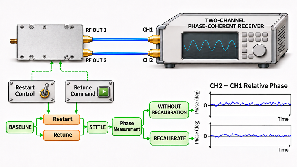
Restart repeatability means recovering the required relative RF phase after a defined event, using only the recovery and calibration steps the project permits. The post-event phase may differ from the stable offset observed during continuous operation.
Test software restarts, full power cycles, carrier retunes, waveform changes, and channel-mode changes separately where relevant. For each event, record the pre-event baseline, configuration, settling period, post-event phase, and calibration state. Use the agreed number of trials to characterize recovery across repeated events.
Specify which recovery mode the project accepts:
- Without recalibration: Does the approved restart or retuning sequence recover the required phase directly?
- With recalibration: Does the measured post-calibration phase meet the limit? Record the method, correction, elapsed time, and residual error.
The HZS1006000-F1 documentation describes channel control, frequency configuration, and restart operations. These commands provide useful test events; measure the recovered RF phase after each applicable sequence.
Agree on the events, trials, settling criteria, and calibration policy in advance. If the report omits an event definition or whether recalibration occurred, its repeatability result cannot be compared or accepted as specified.
5. How Should Temperature Drift and Recalibration Intervals Be Verified?
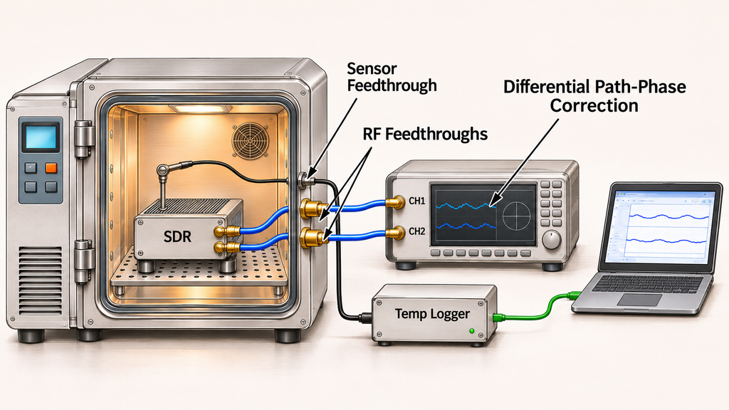
To evaluate phase stability beyond room temperature, record temperature and inter-channel phase together across the specified range.
Measure both the temperature transition and the stabilized state; neither substitutes for the other. Record sensor location, actual temperature, dwell time, channel configuration, and whether RF transmission continued throughout the cycle.
Cables, attenuators, connectors, and receiver channels can also drift with temperature. Use a controlled reference path or characterized fixture response to separate measurement-chain effects from the SDR’s. Document which parts of the setup experienced the temperature cycle.
Include the return-to-baseline result and any pre- or post-cycle recalibration. Use the published operating-temperature range to choose test conditions, then quantify phase drift from measurements.
Set recalibration policy using measured drift, allowable phase error, uncertainty, and service conditions, not an arbitrary calendar interval. A short thermal cycle cannot establish a calendar-based interval on its own; that requires time-dependent stability evidence under relevant operating conditions. Specify whether recalibration is periodic, event-triggered, or required after a temperature excursion. If temperature or fixture behavior is undocumented, restrict the verdict to the conditions actually tested.
6. How Should a Channel-by-Channel Acceptance Matrix Be Built?

A matrix prevents a good result from one channel pair being extrapolated to every output. A two-output source has one direct pair. With more outputs, a fixed reference can simplify the plan if receiver alignment stays traceable. For example, CH2–CH1 and CH3–CH1 are possible entries when CH1 is the reference; these labels do not describe the listed SDR models. Test other pairs directly when the application requires them.
Use a separate row for each required pair, condition, and metric. Record channel IDs, the selected statistic and unit, the project-defined limit and its source clause, the measured result, uncertainty, evidence ID, and disposition. Offset and variation need separate rows if both are contractual. Include the RF output-level settings in the test conditions for each applicable row.
Multi-channel SDR phase-coherence acceptance evidence matrix — blank review template
Swipe horizontally to view all columns.
| Channel pair / reference | Test conditions: frequency, waveform, time, temperature, event | Phase metric and unit | Agreed limit and source | Corrected measured result / raw and corrected records | Uncertainty / calibration basis | Evidence ID | Disposition |
|---|---|---|---|---|---|---|---|
| Enter CHi–CHref IDs | Same carrier and waveform; defined baseline time and start state | Initial offset (° or rad) | Enter project limit, unit, and clause ID | Enter corrected offset and unit; link raw and corrected records | Path-phase calibration and phase uncertainty | Baseline run/report ID | Record after review |
| Enter CHi–CHref IDs | Carrier, waveform, sample rate, observation window, operating state | Select one: maximum absolute deviation, peak-to-peak change, or RMS variation (° or rad) | Enter selected-metric limit and clause ID | Enter corrected statistic and unit; link raw trace and corrected time series | Receiver stability, phase processing, bandwidth, uncertainty | Time-log ID | Record after review |
| Enter CHi–CHref IDs | Frequency grid or waveform bandwidth; record retunes and reference state | Select relative phase response (° or rad) or delay (s) | Enter frequency-dependent limit and clause ID | Enter corrected result at each required frequency; link raw and corrected sweep records | Frequency-dependent path calibration and uncertainty | Sweep-run ID | Record after review |
| Enter CHi–CHref IDs | Software or power restart, trial count, settling state, calibration policy | Select post-restart offset or across-trial phase variation (° or rad) | Enter selected-event-metric limit and clause ID | Enter corrected event statistic and unit; link raw and corrected trial records | Event calibration state and uncertainty | Restart-trial ID | Record after review |
| Enter CHi–CHref IDs | Retune, waveform or channel-mode change; trial count and recovery state | Post-event phase error (° or rad) | Enter recovery limit and clause ID | Enter corrected phase error and unit; link event-aligned raw/corrected records | Reinitialized phase reference and uncertainty | Retune/config log ID | Record after review |
| Enter CHi–CHref IDs | Actual temperature, transition, stabilized state, time and waveform | Drift against temperature baseline (° or rad) | Enter temperature limit and clause ID | Enter corrected thermal drift and unit; link phase and temperature records | Fixture thermal phase change and uncertainty | Thermal-run ID | Record after review |
| Enter CHi–CHref IDs | Elapsed time or agreed trigger; pre/post calibration state | Residual phase error (° or rad) | Enter allowable error, interval, and clause ID | Enter corrected residual error and unit; link dated raw/corrected records | Calibration method, validity and uncertainty | Calibration-record ID | Record after review |
Duplicate the applicable rows for every channel pair and condition, then enter the measured results and evidence references. Apply the agreed uncertainty decision rule, including how to handle results near a limit. Mark any required combination without supporting data for further testing or evidence review.
7. What Evidence Package Is Sufficient for Supplier Acceptance?
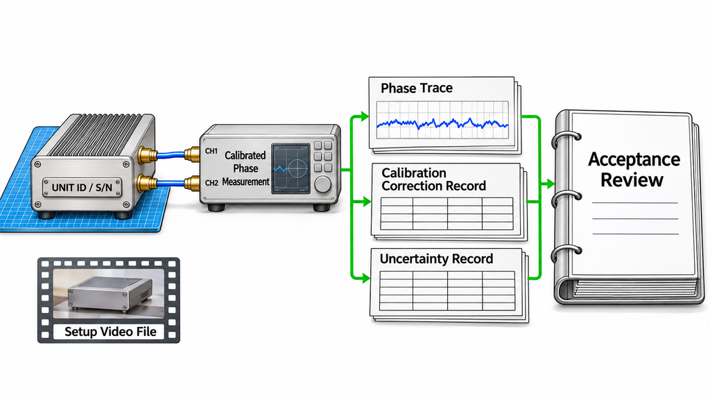
A useful supplier package ties each phase requirement to a measured result and an identifiable SDR unit or sample. Synchronization demonstrations document the setup; traceable phase data support the quantitative acceptance decision.
For each matrix entry, identify the contractual limit, measurement setup, clock and trigger connections, RF paths, and instrument calibration. Attach the raw readings, corrected SDR-port result, statistical method, and uncertainty. Link the time, frequency, restart, retuning, and temperature records to the corresponding entries so another engineer can reconstruct the decision.
Identify the tested model, hardware and firmware versions, channel configuration, and unit identity. If acceptance is serial-number-specific, the serial number must link to the corresponding dataset and result.
Define whether the report covers a development sample, a sampled production lot, or individual units. State the sampling rule and what changes trigger retesting before applying the results to deliveries.
Videos help document connections, operating modes, and test events. For a numerical phase verdict, pair them with the measurement data, corrections, and calibration records.
Use three review outcomes: Accept the measured scope when results meet the agreed uncertainty-aware rule; request evidence or retesting for missing or inconsistent records; or hold acceptance until the limits, calibration, channel data, and tested-unit identity are clear. Record documentation gaps separately from measured product failures.
For either RF SKYPOWER model, request phase records that match the proposed RF-port configuration, hardware revision, firmware, and operating conditions.
Conclusion
Accept phase coherence for the channel relationships and conditions that the measured results support. The results should meet project limits at defined SDR output reference planes and cover the intended frequency, waveform, observation window, state changes, and temperature. Calibrations and uncertainties must be traceable to the tested units.
This framework helps the buyer judge whether the evidence is complete and comparable. The project specification sets the tolerance, while model- and unit-specific results establish the tested scope. Shared-clock or multi-unit control descriptions document synchronization arrangements; the RF phase claim rests on measurements.
Before selecting a final configuration, define the phase metric, limit, channel pairs, and recalibration policy. Request raw and corrected records that cover those conditions and identify the tested units.
For an RF SKYPOWER SDR signal-source engineering review, provide the frequencies, waveforms, simultaneous RF channel count, channel pairs, phase limits, observation window, restart and retuning cases, temperature range, calibration policy, and output reference planes. Include the expected quantity and whether reports should cover samples or individual serial-numbered units. The engineering team can review the proposed RF-port architecture and identify the configuration-specific evidence available for your acceptance plan.